https://doi.org/10.4224/20378479
READ THESE TERMS AND CONDITIONS CAREFULLY BEFORE USING THIS WEBSITE.
https://nrc-publications.canada.ca/eng/copyright
Vous avez des questions? Nous pouvons vous aider. Pour communiquer directement avec un auteur, consultez la première page de la revue dans laquelle son article a été publié afin de trouver ses coordonnées. Si vous n’arrivez pas à les repérer, communiquez avec nous à [email protected].
Questions? Contact the NRC Publications Archive team at
[email protected]. If you wish to email the authors directly, please see the first page of the publication for their contact information.
For the publisher’s version, please access the DOI link below./ Pour consulter la version de l’éditeur, utilisez le lien DOI ci-dessous.
Access and use of this website and the material on it are subject to the Terms and Conditions set forth at Fire Safety Design Guidelines for Federal Buildings
Hadjisophocleous, G. V.; Bénichou, N.
https://publications-cnrc.canada.ca/fra/droits
L’accès à ce site Web et l’utilisation de son contenu sont assujettis aux conditions présentées dans le site LISEZ CES CONDITIONS ATTENTIVEMENT AVANT D’UTILISER CE SITE WEB.
NRC Publications Record / Notice d'Archives des publications de CNRC:
https://nrc-publications.canada.ca/eng/view/object/?id=063cc389-d483-4a62-aa43-b163cf01138d https://publications-cnrc.canada.ca/fra/voir/objet/?id=063cc389-d483-4a62-aa43-b163cf01138d
FIRE SAFETY DESIGN GUIDELINES FOR FEDERAL BUILDINGS
by
George V. Hadjisophocleous and Noureddine Benichou
TABLE OF CONTENTS
TABLE OF CONTENTS... i
EXECUTIVE SUMMARY ... viii
NOMENCLATURE ... ix
1. INTRODUCTION ...1
1.1 General - Purpose and Scope of the Study ...1
1.2 Application of Fire Safety Design Guidelines ...1
1.3 Important Comments about the Fire Safety Guidelines...2
1.4 Outline of the Document...2
1.5 Overview of Performance-Based Fire Safety Design...3
1.5.1 General - why the move? ...3
1.5.2 Structure of performance-based fire safety design ...3
2. QUALITATIVE FIRE SAFETY GOALS...4
2.1 General...4
2.2 Qualitative Goals ...4
3. OVERVIEW OF FIRE SAFETY DESIGN OBJECTIVES ...4
4. BUILDING AND OCCUPANT CHARACTERISTICS...5
4.1 General...5
4.2 Building Characteristics...5
4.3 Occupant Characteristics ...6
5. FIRE INITIATION AND GROWTH ...7
5.1 Purpose...7
5.2 Introduction...7
5.3 Evaluation Procedures ...7
5.3.1 Fire ignition...7
5.3.2 Pre-flashover ...8
5.3.2.1 Rate of fire growth ...9
5.3.3 Production of toxic gases and compartment temperature ...10
5.3.3.1 Concentration of carbon monoxide...10
5.3.3.2 Production of smoke ...11
5.3.3.4 Flame height...12
5.3.3.5 Plume temperature ...13
5.3.3.6 Entrained mass flow rate in plumes ...13
5.3.3.7 Emissivity of the flame ...14
5.3.4 Flashover...14
5.3.5 Post-flashover - fully-developed fires...15
5.3.5.1 Fire compartment temperatures ...17
5.3.6 Decay ...18
5.4 Input and Output for The Evaluation Procedures ...19
5.5 Performance Criteria...20
5.5.1 Minimizing ignition and fire occurrence ...20
5.5.1.1 Ignition/heat energy sources ...20
5.5.1.2 Fuel ignition characteristics ...21
5.5.1.3 Fuel/heat sources interactions...22
5.5.2 Control of fire growth ...22
5.5.3 Flashover...23
5.5.4 Minimization of flashover ...23
5.5.5 Control by detection and suppression...24
6. SPREAD OF SMOKE ...25 6.1 Purpose...25 6.2 Introduction...25 6.2.1 General...25 6.3 Evaluation Procedures ...25 6.3.1 Smoke movement...25
6.3.1.1 Movement of smoke within the compartment of fire origin...25
6.3.1.2 Movement of smoke outside the compartment of fire origin ...25
6.3.1.3 Prediction of smoke movement ...26
6.3.2 Control of spread of smoke...26
6.3.2.1 General...26
6.3.2.2 Factors affecting control of smoke spread ...26
6.3.2.3 Smoke control techniques ...27
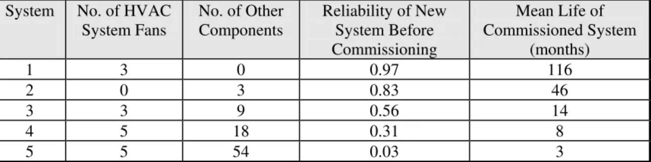
6.3.2.4 Smoke control systems and their design...27
6.3.2.5 Probability of successful activation and reliability of control systems ...29
6.3.2.6 Time of failure of smoke control systems...30
6.3.3 Environmental effects ...30
6.3.4 Interaction of smoke control systems with active systems ...31
6.3.5 Evaluation of properties of smoke ...31
6.3.5.1 Temperature of smoke (average plume temperature) ...31
6.3.5.2 Optical density of smoke and visibility through smoke ...32
6.3.5.3 Concentration of carbon monoxide (CO) ...32
6.3.5.4 Volume of smoke ...33
6.3.5.5 Depth of the hot smoke layer ...34
6.4 Input and Output for the Evaluation Procedures ...34
6.5 Performance Criteria...35
7.1 Purpose...36
7.2 Introduction...36
7.2.1 General...36
7.2.2 Transmission of heat or means of fire spread ...36
7.3 Evaluation Procedures ...37
7.3.1 Heat transfer principles ...37
7.3.2 Spread of fire inside the compartment of fire origin ...38
7.3.3 Spread of fire outside a fire compartment...39
7.3.3.1 Factors affecting fire spread ...39
7.3.3.2 Routes of fire spread ...39
7.3.3.3 Prevention of spread through fire compartmentation design...40
7.3.3.4 Prevention of spread through fire resisting barriers ...41
7.3.3.5 Fire spread from one storey to another ...41
7.3.4 Fire spread to adjacent properties ...43
7.3.4.1 Fire resistance design of fire walls ...43
7.3.4.2 Radiation to adjacent buildings...43
7.3.4.3 Glazing...43
7.3.4.4 Multiple emitting radiation openings...44
7.3.4.5 Separation distances between adjacent buildings ...44
7.3.4.6 Spread from flying brands ...44
7.4 Input and Output for the Evaluation Procedures ...44
7.5 Performance Criteria...45
7.5.1 Glass breakage ...45
7.5.2 Radiation criteria...45
8. FIRE RESISTANCE AND STRUCTURAL STABILITY ...47
8.1 Purpose...47
8.2 Introduction...47
8.2.1 General...47
8.2.2 Factors affecting structural stability ...47
8.3 Evaluation Procedures ...47
8.3.1 Fire severity ...47
8.3.1.1 Compartment temperatures ...48
8.3.1.2 Equivalent time of fire exposure...49
8.3.1.3 Fire duration versus fire severity ...50
8.3.2 Fire resistance of building elements ...51
8.3.2.1 Fire resistance design based on equivalent time...52
8.3.3 Determination of fire resistance...52
8.3.4 Fire resistance of structural steel members...53
8.3.4.1 Methods of protection of structural steel members ...53
8.3.4.2 Critical steel temperatures ...53
8.3.4.3 Temperature rise in structural steel members ...53
8.3.4.4 Fire resistance rating for protected steel ...55
8.3.4.5 Fire resistance rating for unprotected steel ...56
8.3.5 Fire resistance of reinforced concrete and masonry members...57
8.3.5.2 Structural calculation ...58
8.3.6 Fire resistance of structural timber members...58
8.3.6.1 Protective membrane contribution to fire endurance...59
8.3.6.2 Extent of charring of wood members...60
8.3.6.3 Load-carrying capacity of uncharred wood members ...60
8.4 Input and Output for the Evaluation Procedures ...61
8.5 Performance Criteria...62
8.5.1 Structural performance ...62
8.5.2 Existing criteria for barrier fire resistance ...62
9. FIRE DETECTION ...64
9.1 Purpose...64
9.2 Introduction...64
9.2.1 General...64
9.2.2 Fire detection systems...64
9.2.3 Types of fire detectors ...65
9.2.3.1 Heat detectors ...65
9.2.3.2 Smoke detectors ...66
9.2.3.3 Radiation flame detectors ...66
9.2.3.4 Human detection ...66
9.2.3.5 Time delays...66
9.3 Evaluation Procedures ...67
9.3.1 Evaluation of fire detection times ...67
9.3.1.1 Heat detectors ...67
9.3.1.2 Smoke detectors ...70
9.3.1.3 Radiation flame detectors ...71
9.3.2 Fire alarm audibility and visibility...72
9.3.3 Fire detection probabilities ...73
9.4 Input and Output for the Evaluation Procedures ...73
9.5 Performance Criteria...74
10. FIRE SUPPRESSION...75
10.1 Purpose...75
10.2 Introduction...75
10.2.1 Fire suppression systems ...75
10.2.2 Time delays in automatic suppression ...76
10.3 Evaluation Procedures ...76
10.3.1 General...76
10.3.2 Automatic fire sprinkler systems ...76
10.3.2.1 Reduction of heat release rate ...76
10.3.2.2 Probability of control of fires by sprinklers...77
10.3.2.3 Hazard classification of occupancies ...78
10.3.3 Inert gaseous flooding agents ...79
10.3.4 Chemical gaseous flooding agents...79
10.3.5 Water mist suppression systems ...79
10.3.7 Manual suppression ...80
10.3.7.1 Portable fire extinguishers ...80
10.3.7.2 Fire hose reels ...81
10.3.7.3 Hydrant mains systems ...81
10.4 Input and Output for the Evaluation Procedures ...81
10.5 Performance Criteria...82
11. FIRE FIGHTING RESPONSE ...83
11.1 Purpose...83
11.2 Introduction...83
11.2.1 General...83
11.2.2 Time variables in fire fighting activities...84
11.3 Evaluation Procedures ...84
11.3.1 Notification time ...84
11.3.2 Dispatch and arrival times ...84
11.3.3 Search and investigation time upon arrival...85
11.3.4 Life saving and rescue activities time...85
11.3.5 Set-up time for fire attack ...85
11.3.6 Fire control time...85
11.3.7 Fire extinguishment time ...86
11.4 Input and Output for the Evaluation Procedures ...86
11.5 Performance Criteria...87
12. MEANS OF ESCAPE AND SAFE EVACUATION ...88
12.1 Purpose...88
12.2 Introduction...88
12.2.1 General...88
12.2.2 Evacuation sequence...88
12.3 Evaluation Procedures ...88
12.3.1 Total escape/evacuation time...88
12.3.2 Fire discovery time ...89
12.3.3 Response/reaction time ...89
12.3.4 Travel/evacuation time ...90
12.3.4.1 Minimum traversal time...90
12.3.4.2 Travel distance ...91
12.3.4.3 Travelling speed...91
12.3.4.4 Passage time...92
12.3.5 Additional concepts ...94
12.3.5.1 Escape route geometry...94
12.3.5.2 Basis for escape route design...94
12.3.5.3 Minimum time to reach untenable conditions ...95
12.3.5.4 Signage and evacuation plan...95
12.4 Input and Output for the Evaluation Procedures ...95
12.5 Performance Criteria...96
12.5.1 Tenability limits criteria...96
13.1 Purpose...99
13.2 Introduction...99
13.3 Categories of Fire Engineering Models ...99
13.3.1 Probabilistic fire models ...99
13.3.2 Deterministic fire models...100
13.3.2.1 Zone models...100
13.3.2.2 Field models...100
13.4 Selection of Fire Models...100
13.4.1 Limitations and assumptions in fire models ...101
13.4.2 Validation of fire models ...101
13.4.3 Documentation of fire models ...101
13.5 Sensitivity Analysis ...101
13.6 Uncertainty in Fire Models ...101
13.7 Available Fire Engineering Models ...102
14. FIRE SAFETY MANAGEMENT ...105
14.1 Purpose...105
14.2 Introduction...105
14.3 Fire Safety Manual...105
14.3.1 Purpose of the manual...105
14.3.2 General description of the contents of the manual ...105
14.3.2.1 Responsibilities ...106
14.3.2.2 Fire action procedures upon discovery of a fire emergency ...106
14.3.2.3 Emergency procedures...106
14.3.2.4 Housekeeping procedures ...106
14.3.2.5 Maintenance and inspection procedures ...107
14.3.2.6 Information and training ...107
14.3.3 Review and update of the manual...107
14.4 Example of a Typical Fire Safety Manual ...107
14.4.1 Fire safety responsibilities ...108
14.4.2 Fire action procedures...109
14.4.3 Emergency procedures...109
14.4.3.1 Useful phone numbers in case of emergencies ...109
14.4.3.2 Evacuation procedure ...110
14.4.3.3 Fire emergency procedure ...110
14.4.3.4 Hazardous material spill procedure ...111
14.4.3.5 Natural gas leak procedure ...111
14.4.3.6 Odours...111
14.4.3.7 First aid - clothes on fire ...111
14.4.4 Housekeeping procedures ...112
14.4.4.1 Fire prevention practices...112
14.4.4.2 Safe storage of hazardous materials...113
14.4.4.3 Hazardous waste disposal ...113
14.4.5 Maintenance/inspection procedures...114
14.4.5.1 Maintenance...114
14.4.6 Information and training ...114
14.4.6.1 Information ...114
14.4.6.2 Staff training ...115
15. REFERENCES ...116
APPENDIX A - FIRE SAFETY OBJECTIVES ...123
APPENDIX B - FIRE LOAD DENSITIES...128
APPENDIX C - FIRE HAZARDS AND IGNITION SOURCES...135
APPENDIX D - FIRE PROTECTION SYSTEMS AND EQUIPMENT ...137
FIRE SAFETY DESIGN GUIDELINES FOR FEDERAL BUILDINGS
by
George V. Hadjisophocleous and Noureddine Benichou
EXECUTIVE SUMMARY
Building codes in many countries around the world are shifting from prescriptive- based to performance-based due to economic and social reasons as well as a result of progress in fire safety technology and the development of engineering tools that are required to implement such codes. The approach used to develop performance-based codes follows a transparent, hierarchical structure in which there are usually three levels. The top level objectives usually state the functional requirements and the last level the performance criteria. Usually one middle level exists but more levels can be used in this hierarchical structure depending on the complexity of the requirements. The middle level outlines the fire safety design guidelines that must be used to satisfy the objectives.
The success of performance-based codes depends on the ability to establish the necessary fire safety design guidelines along with the performance criteria that are verifiable and enforceable.
The present study is part of a joint research project of the National Fire Laboratory, Institute for Research in Construction, National Research Council of Canada, partially funded by the Department of National Defence and Public Works and Government Services Canada. The purpose of the project is to develop fire safety design guidelines that can be used for the design of fire protection systems in Canadian federal buildings. These design guidelines will allow for the design of flexible and cost-effective fire protection systems without compromising the safety of the occupants.
The fire safety design guidelines contained in this document are based on the extensive literature survey on performance-based regulations undertaken at the National Fire Laboratory by Hadjisophocleous, Benichou and Tamim (1996), the New Zealand Design Guide (1994), the Australian Fire Engineering Guidelines (1996), the British Standards Institute Draft Code of Practice (1994), and the Nordic Building Regulations (1994). The document also provides guidance to designers in applying the fire safety design guidelines in order to protect building occupants and property from undesirable fires.
In addition, this document presents the performance criteria that can be used in designing fire protection systems in buildings and the models used to determine whether the design criteria are met by the proposed designs. The models are presented along with their limitations and availability. Furthermore, the policies and procedures used for fire safety management are also examined.
NOMENCLATURE
Ae = Area of an enclosing rectangle containing all of emitting openings, m2 Af = Area of the compartment floor, m2
Afire = Area of fire, m2
Ao = Area of openings, m2
Ast = Cross sectional area of the steel section, m2
At = Surface area of the compartment including openings, m2 AT = Total area of the compartment enclosing surfaces, m2 c = Specific heat capacity of the material, kJ/kg·K ci = Specific heat of insulating material, J/kg °C cp = Specific heat of gas at constant pressure, kJ/kg·K cst = Steel specific heat, J/kg °C
Cw = Pressure coefficient CF = Conversion factor, min/MJ/m2
CO(ppm) = Concentration of carbon monoxide in parts per million Conco = Concentration of carbon monoxide, kg/m3
C1 = Radiation reduction factor
C2 = A value of 0.5 for sprinklered buildings and a value of 1.0 for all others C3 = Importance factor
C4 = Proportionality constant for the detector
C5 = A factor
d = Distance between the fire and the detector, m
dl = Distance between the incident light source and the point where the effective intensity is measured, m
D = Effective diameter of the fire source, m Dm = Mass optical density, m2/g
Do = Occupant density, persons/m2 E = Effective intensity, lumens/m2 Fc = Actual flow of occupants, persons/s
Ff = Facade factor
Fs = Specific flow, persons/m·s G = Length of the stair tread, m g = Acceleration due to gravity, m/s2
h = Heat transfer coefficient from exposure to steel member, W/m2·K hc = Convective heat transfer coefficient, W/m2·K
hk = Effective heat transfer coefficient, W/m2·K hr = Radiative heat transfer coefficient, W/m2·K
Hc = Calorific value of the fuel or heat of combustion, MJ/kg Hcomp = Height of the compartment, m
Hd = Calorific value of the dry material, MJ/kg Ho = Height of ventilation openings, m
Hp = Heated perimeter of the steel section, m
Hw = Average height of the openings weighted with respect to each individual opening area, m
Io = Radiated power received without smoke Is = Radiated power received with smoke
k = Thermal conductivity, kW/m·K
kg = Fire growth parameter, s/MW1/2
ki = Thermal conductivity of insulation material, W/m°C lc = The height of the continuous flame, m
li = The height of the intermittent flame, m
lm = Mean flame height, m
L = Fire load, kg
Lop = Optical measuring length, m
Lt = Travel length, m
mc = Total mass of each combustible material in the compartment, kg mf = Mass of fuel burnt, kg
m• = Mass flow rate, kg/s
ment
•
= Entrained mass flow rate in plume, kg/s
mf
•
= mass rate of fuel burnt, kg/s
msmoke
•
= mass rate of smoke produced, kg/s
M = Moisture content in percentage by dry weight Md = Moisture content, %
N = Number of storeys
NP = Number of persons passing through door or stairway OD = Optical density, dB/m
P = Projection of the flame tip from the wall, m Pd = Radiant power emitted by the detector, W Pf = Perimeter of fire, m
Pw = Wind pressure, Pa
qf = Fire load density per floor area, MJ/m2 qc = Convection heat flux, W/m2
qr = Radiation heat flux, W/m2
qrc = Critical received radiation, W/m2 qx = Heat flux in the x direction, W/m2
Q = Heat release rate, kW
Q(tact) = Heat release rate at the activation time, kW
Qc = Convective heat release rate (may usually be assumed as 0.7 Q), kW Qcom = Rate of heat release in the compartment produced by combustion, kW Qfo = Rate of heat release at flashover, kW
Qg = Rate of accumulation of heat in hot gases in the compartment, kW Ql = Rate of heat loss by convection through openings, kW
Qmax = Heat release during fully developed burning phase, kW Qpeak = Peak heat output of the total fire area, kW
Qr = Rate of heat loss by radiation through openings, kW
Qw = Rate of heat loss by radiation and convection to the compartment walls, kW
Q(t) = The heat release rate as a function of time t, kW Q(t- tact) = Heat release rate after the activation time, kW
r = Radial distance between the axis of the fire and the detector, m
rf = Ratio of the design action on the member under the design load for fire to the design capacity of the member at room temperature
R = Riser height of each step, m RTI = Response Time Index, (m·s)0.5
s1 = Length between two detectors in a rectangle of four, m s2 = Width between two detectors in a rectangle of four, m S = Radiant power reaching the detector, W
St = Travel speed, m/s
SF = A safety factor
t = Time, s
ta = Time from detection to alarm sounding, s tatt = Fire attack time, min
tact = Time at the sprinkler activation, s tb = Duration of burning period, s tc = Fire control time, min
td = Time from fire ignition to fire detection, s tdis = Dispatch time, min
te = Equivalent severity time of fire exposure to the standard test, min ted = Design fire severity, min
teva = Travel or evacuation time, s tex = Fire extinguishment time, min
tfb = Duration of fully developed burning, s tfd = Time of fire discovery, s
ti = Time to investigate, collect goods, fight the fire, etc., s tinv = Search and investigation time after arrival, min
tls = Life saving and rescue activities time, min
tn = Time to notify the fire department of the emergency, min to = Time from alarm to making a decision to respond, s tod = Time of onset of the decay phase, s
tp = Thermal penetration time, s tpas = Passage time through an exit, s tpm = Pre-movement time, s
tr = Fire resistance rating or time to reach a critical temperature, min tres = Response or reaction time, s
tt = Travel time to arrive to the burning area, min ttot = Total required time, s
ttr = Minimum traversal time to an exit, s
tunt = Minimum time to reach untenable conditions measured from ignition, s
tv = Time delay, min
∆t = Time step, s
∆tf = Effective fire duration, s
T = Temperature, °C
Te = Temperature of the emitting source/surface, K Tf = Temperature of flames in smoke plume, K Tg = Expected compartment temperature, K Tl = Lower layer temperature, K
TL = Limiting steel temperature, °C
To = Ambient temperature, K
Tr = Temperature of the receiving surface, K Ts = Smoke temperature, °C
Tst = Steel temperature at time t, K Tu = Upper layer temperature, K
∆T = Temperature difference between the surface and fluid, K ∆Tp = Temperature rise on plume centreline, K
∆Tst = Temperature rise in steel for the duration ∆t, °C u = Instantaneous velocity of hot fire gases, m/s
uo = Velocity of hot gases at which το was measured, m/s
Vs
•
= Volume rate of smoke production at a specified temperature, m3/s Vt = Total volume of smoke generated at time t, m3
Vw = Wind velocity, m/s VF = Ventilation factor
Y = Distance between floor and bottom smoke layer under ceiling, m Yco = Carbon monoxide yield factor, kg/kg
w = Spray density, mm/s
We = Effective width, m Wmin = Minimum aisle width, m Wo = Width of the window, m
Wst = Steel weight per unit length, kg/m
Ww = Width of the wall containing openings, m x, y, z = Rectangular co-ordinates, m
z = Height above top of the fire source, m
zo = Height of virtual origin above top of the fire source, m
Z = Flame height above the top of the opening of the burning floor, m
Greek Symbols
α = Thermal diffusity, α = k / (ρ c), m2/s δ = Thickness of compartment surface, m δf = Thickness of the flame, m
δi = Thickness of insulation material, m ε = Emissivity of the surface
εf = Emissivity of the flame
εsmoke = Smoke mass conversion factor, kg/kg φ = Configuration factor (0 < φ < 1)
ρ = Material density, kg/m3
ρo = Ambient (outside) air density, kg/m3
ρs = Density of air as smoke at a temperature T in °C, kg/m3 σ = Stefan-Boltzman constant (5.67 x 10⁻⁸ W/m2·K4) τ = Detector time constant, s
το = Detector time constant measured at reference velocity uo, s ζ = Extinction coefficient of air
FIRE SAFETY DESIGN GUIDELINES FOR FEDERAL BUILDINGS
by
George V. Hadjisophocleous and Noureddine Benichou
1. INTRODUCTION
1.1 General - Purpose and Scope of the Study
This study is part of a joint research project of the National Fire Laboratory, Institute for Research in Construction, National Research Council of Canada, with the Department of National Defence and Public Works and Government Services Canada. The purpose of the project is to develop fire safety design guidelines that can be used for the design of fire protection systems in Canadian federal buildings. These fire safety design guidelines will permit the assessment of fire safety in buildings and the ability of the fire protection systems to achieve established objectives. Minimum objectives are those stated in the National Building Code (1995) and National Fire Code (1995) of Canada, however, the design team may state additional objectives. The design guidelines will also allow flexible and cost-effective fire safety designs without compromising the safety of the occupants. The document also provides the necessary guidance to designers in applying the fire safety design guidelines as a means to prevent undesirable fires.
The fire safety design guidelines contained in this document are based on the extensive literature survey on performance-based regulations undertaken at the National Fire Laboratory by Hadjisophocleous, Benichou and Tamim (1996), the New Zealand Design Guide (1994), the Australian Fire Engineering Guidelines (1996), the British Standards Institute Draft Code of Practice (1994), and the Nordic Building Regulations (1994).
1.2 Application of Fire Safety Design Guidelines
The fire safety design guidelines presented in this report are applicable to the following:
• Design of fire protection systems in existing buildings (renovations, change of use, etc.)
• Design of fire protection systems in new buildings especially those in which the National Building Code (1995) and National Fire Code (1995) of Canada are limited in application
• Establishment of equivalency to the requirements of the National Building Code (1995) and National Fire Code (1995) of Canada
1.3 Important Comments about the Fire Safety Guidelines
The fire safety design guidelines are neither a design code nor a document intended to replace the National Building Code (1995) and National Fire Code (1995) of Canada. Rather, it provides guidance that permits fire safety engineers to satisfy rationally the objectives set by the National Building Code (1995) and National Fire Code (1995) of Canada. This document may also be used to support the work being conducted by the Canadian Commission on Building and Fire Codes to develop objective-based building and fire codes by the year 2001 as outlined in their Strategic Plan (1994).
The procedures outlined in this document are intended to be used by competent and qualified fire safety engineers, i.e., engineers that are aware of the behaviour of building materials, structural components and occupants when exposed to fire. In addition, it must be emphasized that fire safety design requires the use of engineering and expert
judgement, practical experience, and a thorough understanding of the limitations and assumptions involved in the methodologies used.
The fire safety design guidelines presented herein can also be used by code officials to assess designs submitted for approval. Building owners, architects, insurance
companies and the fire department personnel could use these guidelines to provide valuable tips to fire safety designers.
The methodologies and equations presented in this document are not exhaustive. The use of alternative design approaches can be used provided they are technically sound and justified by the designer.
This document is open to improvement and expansion with new developments in fire research and with feedback from users, i.e., code officials, consultants and the fire community at large.
1.4 Outline of the Document
The fire safety design guidelines are comprised of a set of Sections that guide fire safety engineers in the preparation of detailed fire engineering designs. Code officials can also use the guidelines to verify the adequacy of the designs. Included in this document are the following Sections:
1. An introduction outlining the purpose, scope, applicability of the guidelines and an overview of performance-based fire safety design. This is followed by Sections on the qualitative fire safety goals, an overview of the fire safety design guidelines and a brief discussion on characterization of buildings and occupants.
2. Sections 5 to 12 present a detailed analysis for each component of the fire safety design guideline namely, fire initiation and growth, smoke production and movement, fire spread, fire resistance and structural stability, fire detection, fire suppression, fire department response, and safe evacuation. In each Section, methodologies,
procedures and equations are provided, as well as performance criteria for use in assessing the design.
3. Section 13 provides information on engineering fire models as well as a list of the computer models that are available.
4. Section 14 discusses fire safety management. This Section explains the
responsibilities of the building manager/owner and the occupants vis-à-vis fire safety, the procedures that should be in place to prevent a fire from occurring as well as the actions to take in the event of a fire emergency.
1.5 Overview of Performance-Based Fire Safety Design
1.5.1 General - why the move?
In recent years, building codes, regulations and standards have been going through a transition from being prescriptive-based to being performance-based. Many countries are in the process of developing performance-based fire safety regulations and the engineering criteria required to support these regulations. The reasons behind the move towards the performance approach are the expected advantages that the performance-based fire safety design can offer over the prescriptive design, which can be summarized as follows:
• Establishing clear safety goals and leaving the means of achieving those goals to the designer
• Permitting innovative design solutions that meet the established performance requirements
• Eliminating technical barriers to trade for a smooth flow of industrial products • Allowing international harmonization of regulation systems
• Permitting the use of new knowledge as it becomes available • Allowing cost-effectiveness and flexibility in design
• Enabling the prompt introduction of new technologies to the marketplace • Eliminating the complexity of the existing prescriptive regulations 1.5.2 Structure of performance-based fire safety design
The development of performance-based fire safety design follows a hierarchical structure in which there are usually three levels. The top level states the functional goals, the middle level gives the fire safety design guidelines, and the last level provides
acceptance criteria. In the literature survey conducted at the National Fire Laboratory, Hadjisophocleous, Benichou and Tamim (1996), it was suggested that the approach used to develop performance-based fire safety design is as follows:
• Identification of quantitative design guidelines and the establishment of fire safety acceptance criteria and safety factors that go along with these guidelines,
• Establishment of evaluation tools and methods for the quantification process. 2. QUALITATIVE FIRE SAFETY GOALS
2.1 General
The implementation of a rational fire safety design requires a definition of its operational goals. It is, therefore, important to establish goals that are clearly defined and accepted by society as a whole. In some situations, however, for the benefit of a
community, additional goals may be specified by the community, insurance companies or the building owner.
2.2 Qualitative Goals
The overall objectives of the fire safety system in a building are:
1. To protect the life and health of people from fires.
This includes, but is not limited to, incapacitation due to exposure to heat, smoke, toxic gases and structural instability.
2. To protect the property in the building of fire origin and adjacent buildings.
This includes, but is not limited to, damage or loss to building contents, spread of fire of other compartments and other buildings, and structural failure of building.
3. To limit the economic, social and environmental impacts from fires.
Failure to meet the above qualitative goals implies losses to society in terms of human and physical resources. These goals and the fire safety design objectives stated in the following Section are based on the summary of objectives and requirements given in Appendix A. These objectives and requirements are based on the literature survey conducted by Hadjisophocleous, Benichou and Tamim (1996).
3. OVERVIEW OF FIRE SAFETY DESIGN OBJECTIVES
The qualitative goals outlined in Section No. 2 are very general and require further refinement. This refinement is achieved by sub-dividing each goal into a number of design objectives so that they can be easily quantified. These design objectives are not independent from each other and from any other part of the fire safety system such as the qualitative goals. Indeed, all components of one level of the design guidelines interact with each other and every level interacts with the one next to it in the structured fire safety system.
A number of factors, including building characteristics, occupant characteristics, means of safe evacuation, means of fire detection and suppression and structural stability, must be taken into account in establishing the fire safety goals. The following is a set of design objectives to be considered when conducting a fire safety design:
1. Avoidance of fire occurrence/outbreak; 2. Limitation of fire growth;
3. Avoidance of smoke spread; 4. Avoidance of fire spread;
5. Assurance of safe load-bearing structure; 6. Effective use of detection systems; 7. Effective use of suppression systems; 8. Effective use of fire fighting service; 9. Assurance of safe escape and evacuation; 10. Assurance of continuity of operations; 11. Assurance of environmental protection.
This wide range of possible building uses does not permit the development of a single set of design goals that can be applied to all buildings. In addition, the potential interactions between a fire and the building and its occupants give rise to a large number of possible fire scenarios. Appropriate fire scenarios must be selected for the design of the fire protection systems.
4. BUILDING AND OCCUPANT CHARACTERISTICS
4.1 General
A common and important factor in the quantification of fire protection systems is the characterization of buildings and occupants. Therefore, before getting into the details of the design guidelines, it is worthwhile introducing these characterizations.
The fire safety design objectives outlined in Section No. 3 depend on the
characteristics of the building to be designed and the occupants of the building. Thus, prior to beginning any fire safety design, information about the building, its contents and its occupants must be gathered. This information will provide an indication of the probable occurrence of events such as fire development, fire spread and potential impact to humans and property. The data needed to assess the characteristics of the buildings and occupants is presented below.
4.2 Building Characteristics
Building characteristics affecting the design of fire safety systems include:
• Dimensions of the building and its components (structural and non-structural); • Properties of the materials forming the building;
• Locations of means of fire detection and fire suppression; • Locations of routes of escape;
• Amount of combustible materials in the building; • Monetary value of contents;
• Ways of storage of contents. 4.3 Occupant Characteristics
The characteristics of the occupants in a building affect their ability to avoid untenable conditions that may develop due to the occurrence of a fire. In order to appropriately design for life safety in buildings, it is of prime importance to have a detailed knowledge of the capabilities and behaviour of the occupants of a building. The capabilities and behaviour of the occupants in a fire emergency, in terms of response and evacuation, depend on many parameters. These include:
• Familiarity of the occupants with the building;
• Existence of proper signage for evacuation towards a safe place; • Complexity of the construction of the occupancy;
• Number of occupants and occupants with disabilities;
• Training of occupants in evacuation process and the use of fire extinguishing means; • Age of occupants.
5. FIRE INITIATION AND GROWTH
5.1 Purpose
• To provide methodologies for the evaluation of the rate of fire growth, the production of heat and toxic gases, the occurrence of flashover and the characteristics of post-flashover fires.
• To develop guidelines to minimize the likelihood of fire occurrence and the rate of fire growth and the occurrence of flashover.
5.2 Introduction
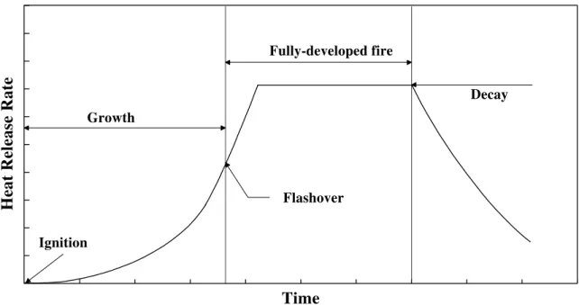
During its life, a fire goes through four distinct stages, usually characterized in terms of the average temperature of compartment gases: fire initiation or ignition which is defined as the onset of combustion; the pre-flashover or growth period during which the fire is localized to a few burning objects; the post-flashover or fully-developed stage during which the fire engulfs the whole compartment; and the decay stage. The transition from the growth stage to the fully-developed stage is known as flashover.
These typical fire stages are shown in Figure 5.1, which plots the fire heat release rate with time. Ignition, the rate of fire growth during the growth period, the time to flashover, the maximum heat release rate, the duration of the fully-developed period and the decay rate for different fires vary widely. It should be mentioned that the four stages cannot be identified for all fires. This Section will describe the parameters affecting the fire during each of these stages and provide evaluation methods to determine the fire and compartment characteristics.
5.3 Evaluation Procedures
5.3.1 Fire ignition
Fire is a chemical reaction known as combustion. It is defined by the rapid oxidation of a combustible material accompanied by release of energy in the form of heat. In order for ignition to occur, the presence of both a fuel and a heat energy source is required. When the two come together, with the appropriate proportions, either by a lack of separation or by some type of active interaction, a fire occurs. There are three modes of ignition:
1. Pilot ignition: Occurs when released flammable gases are ignited by a flame or an electrical spark.
2. Non-pilot ignition: Occurs when the temperature of the pyrolysis gases is such that the energy produced by the exothermic reaction of the pyrolysis is enough to ignite the volatile mixture of oxygen and the released gases.
3. Spontaneous ignition: Occurs when there is sufficient oxidation reaction energy to raise the temperature above the ignition point (in the absence of a flame or a spark).
The probability of occurrence of ignition within a room or a compartment depends upon a number of parameters, including:
1. Heat or ignition sources present and the available ignition energy; 2. Flash point of flammable liquids in the compartment;
3. Flammability limit of combustible vapours released from the fuel; 4. Ignitability characteristics of fuels that are near ignition sources; 5. Critical temperatures of materials in the compartment;
6. Separation or arrangement of fuels and heat sources;
7. Building management characteristics (housekeeping, maintenance, inspection, training and security of the building).
Heat Release Rate
Time Decay Fully-developed fire Flashover Growth Ignition
Figure 5.1. Typical stages of fire growth
5.3.2 Pre-flashover
Following ignition, fires may go through a smouldering phase before flames are initiated. Smouldering fires develop very slowly with periods of up to several hours. With lack of ventilation, smouldering fires may self extinguish. However, with increased ventilation, they may develop into flaming fires. Smouldering fires are a threat to life because of the generation of smoke and toxic gases such as carbon monoxide (CO) that
can spread throughout the building. In addition to the influence of ventilation, the characteristics of smouldering fires depend on the nature of the burning material and the strength of the source of ignition.
The development of a fire during the pre-flashover flaming stage is very important as it determines the time when untenable conditions will be reached and the time when the detection and suppression systems will activate. For this reason, it is essential to predict the rate of fire growth, and the production of heat and toxic gases.
5.3.2.1 Rate of fire growth
The rate of growth of fires during the pre-flashover stage and the production of heat and toxic gases depend on fuel properties, such as ignitability, heat of combustion, fuel quantity and arrangement, proximity of first ignited item to other combustible items and the properties of the compartment lining materials, such as thermal absorptivity and ignitability and the compartment size, geometry and ventilation conditions.
The rate of fire growth can be determined using experimental results, computer models or empirical correlations. One of the most-used estimates for fire growth is the t-squared (t2) fires.
For a t2 fire, the heat output for an ignited item is assumed to increase according to a quadratic function of time. The fire growth rate is defined in terms of the fire growth parameter, kg. The heat release rate, Q, is given by:
Q = 1000⋅( /t kg)2 (5.1)
where: Q = heat release rate, kW;
t = time, s;
kg = fire growth parameter which is defined as the time (in s) for fire to reach a heat output of 1000 kW, s/MW1/2 (see Table 5.1 for values).
Table 5.1 shows fire growth rates and their corresponding fire growth parameters as defined in the New Zealand Design Guide (Buchanan, 1994).
For t2 fires, the fire is assumed to continue to grow until either the fuel is totally consumed or the heat release rate reaches a peak value. The peak heat release rate is dependent upon the burning object and may be estimated based on the fire area and the specific rate of heat release per unit area, if known, as:
Qpeak = ′′ ⋅Q Afire (5.2)
where: Qpeak = peak heat output of the total fire area, kW; Q" = heat output per unit area of fire, kW/m2;
Afire = total area of fire, m2.
Table 5.1. Typical fire growth rate parameters (Buchanan, 1994)
Rate of Fire Growth
kg
(s/MW1/2)
Typical Equivalent or Real Fire
Slow 600 Solid wooden material with a horizontal orientation such as floors.
Medium 300 Solid wooden furniture such as desks; cotton/polyester spring
mattress; etc.
Fast 150 Light wooden furniture such as plywood wardrobes; full mail
bags; plastic foam; stacked timber pallets; etc.
Ultra Fast 75 Upholstered furniture; some pool fire; lightweight drapes; etc.
In the absence of data, the maximum heat release rate per unit area, Q" can be assumed as shown in Table 5.2. Then, knowing kg and Qpeak, the time to reach the peak heat output of the fire can be estimated.
Table 5.2. Maximum design heat release rates (BSI, 1994)
Occupancy Type Maximum Heat Release Rate
(kW/m2)
Offices, Schools, Dwellings, Hotels 250
Shops, Retail, Places of Assembly 500
5.3.3 Production of toxic gases and compartment temperature
Experiments have shown that conditions inside the room or compartment of fire origin become life-threatening for the occupants well before flashover due to the production of CO and other toxic gases and smoke, oxygen depletion and high
temperatures. Evaluating these conditions in the compartment of fire origin during the pre-flashover stage is important to determine whether occupants have sufficient time to evacuate the building. Knowledge of these conditions is also needed to estimate the time of smoke detector and sprinkler activation.
5.3.3.1 Concentration of carbon monoxide
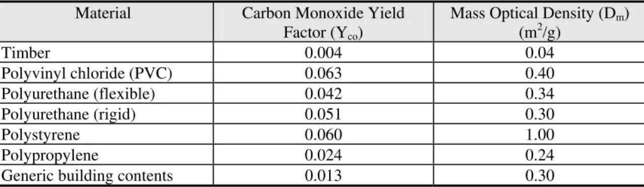
The principal toxic gas produced by a fire is carbon monoxide. The concentration in parts per million (ppm) of CO at 20°C in the combustion products can be estimated as follows: CO ppm Y m V co f t ( )= 0 858 10. ⋅ ⋅ ⋅ 6 (5.3)
Vt = volume of smoke generated at time t, m3; mf = mass of fuel burnt, kg.
Table 5.3. Typical product yield for flaming combustion (Australian Guidelines, 1996)
Material Carbon Monoxide Yield Factor (Yco)
(kg/kg) Timber 0.004 Polyvinyl chloride (PVC) 0.063 Polyurethane (flexible) 0.042 Polyurethane (rigid) 0.051 Polystyrene 0.060 Polypropylene 0.024
Generic building contents * 0.013
*
The data for the generic building contents may be applied to residential, office and retail premises where there is a typical mixture of combustible contents.
5.3.3.2 Production of smoke
Although smoke generation does not greatly affect fire growth, it affects occupant safety as it reduces visibility causing disorientation of occupants. Smoke production varies from material to material as shown in Table 5.4, hence, it is important to limit smoke producing materials in exit ways. The production of smoke can be computed using:
msmoke smoke f
• •
=ε m⋅ (5.4)
where: msmoke = mass rate of smoke produced, kg/s; •
mf
•
= mass rate of fuel burnt, kg/s;
εsmoke = smoke mass conversion factor, kg/kg (see Table 5.4 for values). 5.3.3.3 Compartment temperatures
The temperature in the compartment of fire origin is another parameter that affects life safety. High temperature leads to ignition of nearby objects and eventually the onset of flashover. It also affects the integrity of fire barriers and structural elements of the building. McCaffrey, Quintiere and Harkleroad (1981) proposed the following relationship to predict temperature during pre-flashover:
T T Q g c T A H h A g c A H g o p o o o o k T p o o o − = ⋅ ⋅ ⋅ ⋅ ⋅ ⎡ ⎣ ⎢ ⎢ ⎤ ⎦ ⎥ ⎥ ⋅ ⋅ ⋅ ⋅ ⋅ ⎡ ⎣ ⎢ ⎢ ⎤ ⎦ ⎥ ⎥ − 480 2 3 1 3 ρ ρ / / (5.5)
where: Tg = temperature of the upper gas layer, K; To = ambient temperature, K;
g = acceleration due to gravity, m/s2; cp = specific heat of gas, kJ/kg·K; ρo = ambient air density, kg/m3; Q = heat release rate of the fire, kW; Ao = area of opening, m2;
Ho = height of opening, m;
AT = total area of the compartment enclosing surfaces, m2; AT = Awalls + Afloor + Aceiling - Aopenings
hk = effective heat transfer coefficient (see Equation (5.6)), kW/m·K.
h k t t h k c t t t t c k k p k p p = > = ⋅ ⋅ ≤ ⋅ ⋅ ⎧ ⎨ ⎪⎪ ⎩ ⎪ ⎪ / ( / δ ρ ρ δ ) = ( / ) ( / ) / 1 2 2 2 (5.6)
where: k = thermal conductivity of compartment surface material, kW/m·K; δ = thickness of compartment surface material, m;
ρ = density of compartment surface material, kg/m3;
c = specific heat of the compartment surface material, kJ/kg·K; t = time of exposure, s;
tp = thermal penetration time, s.
Table 5.4. Smoke production for wood and plastic (BSI, 1994)
Material Smoke Mass Conversion Factor (εsmoke)
(kg/kg) Douglas Fir Hardboard Fibreboard PVC Polyurethane (flexible) Polyurethane (rigid) Polystyrene Polypropylene PMMA Polyoxymethylene 0.025 0.001 0.010 0.120 0.035 0.090 0.170 0.010 0.020 ∼ 0 5.3.3.4 Flame height
In order to determine the potential ignition of adjacent fuel, detect the flame and determine the severity of fire spread, it is important to calculate the flame height. The height of the continuous flame, lc (m), can be evaluated by:
l = 0.08 Qc ⋅ 2/ 5 (5.7)
The height of the intermittent flame, li (m), can be estimated by:
l = 0.20 Qi ⋅ 2/ 5 (5.8)
Heskestad in the SFPE Handbook (1995), predicted the mean flame height, lm (m), taken as a mean value above the fire source according to the following equation:
lm = −1 02. ⋅ +D 0 235. ⋅Q2 5/ (5.9)
where: D = effective diameter of the fire source (fire source area = π D2/4), m. 5.3.3.5 Plume temperature
The mean plume temperature rise at the centreline of the flame can be estimated using the following equation (Heskestad, SFPE Handbook (1995)):
∆T T g c Q z z p o p o c o = ⋅ ⋅ ⋅ ⎡ ⎣ ⎢ ⎢ ⎤ ⎦ ⎥ ⎥ ⋅ ⋅ − − 9 1 2 2 1 3 2 3 5 3 . / / / ρ ( ) (5.10)
where: ∆Tp = temperature rise on plume centreline, K;
Qc = convective heat release rate (may be assumed as 0.7 Q), kW; z = height above top of the fire source, m;
zo = height of virtual origin relative to the base of the fire source (see Heskestad, SFPE Handbook (1995), for detailed calculations), m.
5.3.3.6 Entrained mass flow rate in plumes
The plume generated by the fire carries the products of combustion towards the ceiling. As it moves upwards, it entrains air which is then mixed with the hot gases. The amount of entrained air depends on the fire size and the distance between the fire and the hot layer. The growth and properties of the smoke layer depend on the entrained mass flow rate of the plume. Heskestad in the SFPE Handbook (1995), proposed the following equation to predict the entrained mass flow rate:
m g c T Q z z Q g c T z z ent o p o c o c p o o o • = ⋅⎡ ⎣ ⎢ ⎢ ⎤ ⎦ ⎥ ⎥ − + ⋅ − ⎡ ⎣ ⎢ ⎢ ⎤ ⎦ ⎥ ⎥ 0 196 1 2 9 2 1 3 1 3 5 3 2 3 1 2 2 3 5 3 . ( ) . ( ) ( / / / / / / ρ ρ ) / (5.11)
where: ment = entrained mass flow rate in plume, kg/s. •
If the virtual origin correction is negligible, the entrained mass flow rate shown in Equation (5.11) can be written as (Klote, 1994),
ment Qc z
•
= 0 071. ⋅ 1 3/ ⋅ 5 3/ +0 0018. ⋅Qc (5.12) In addition to Equations (5.11) and (5.12), Peacock et al (1993) state that for a
plume where the height to the upper layer is large and the fire size is small, the mass flow rate entrained into the plume is limited by the following relation:
m Q c T T ent p u l • < − ( ) (5.13)
where: Tu = upper layer temperature, K; Tl = lower layer temperature, K.
5.3.3.7 Emissivity of the flame
Radiation fluxes from the flames to other objects in the compartment and the compartment boundaries depend on the temperature of the flames and the flame emissivity. For a luminous flame, the emissivity can be estimated as follows:
ε δ
f e
f
= − − ⋅
1 ( 0 3. ) (5.14)
where: εf = emissivity of the flame; δf = thickness of the flame, m. 5.3.4 Flashover
As the fire continues to grow, the temperature in the compartment of fire origin increases and every part of the compartment is exposed to flame radiation that leads to an event called flashover. Flashover is also characterized by the rapid transition from a localized fire to combustion of all exposed fuel surfaces within a compartment. Because of the undesirability of the flashover event, it is of prime importance to know the
likelihood and timing of flashover. Parameters influencing the time and likelihood of occurrence of flashover include:
• Fuel load in the compartment; • Ignitability of the fuel;
• Temperature and thickness of the upper hot gas layer; • Heat radiation from the flames;
• Distance between the fuel surface and the upper hot gas layer.
It is very unlikely to survive in a fire that has reached flashover. This is due to the high temperatures, lack of oxygen, high CO concentration and heavy smoke.
An important aspect of flashover is the rate of heat release once this key event has occurred. Thomas (1981) developed an empirical equation to estimate the rate of heat release necessary to cause flashover. This formula is given by:
Qfo = . 7 8AT + 378Ao Ho (5.15)
where: Qfo = rate of heat release at flashover, kW.
In addition to Equation (5.15), McCaffrey et al (1981) proposed the relationship shown in Equation (5.16) to predict the rate release rate that causes flashover. The authors used the same method that was used to predict the temperature in a compartment during pre-flashover given by Equation (5.5).
(
Qfo = g c⋅ p ⋅ o ⋅To ⋅⎛Tg −To hk AT Ao Ho ⎝⎜ ⎞ ⎠⎟ ⎡ ⎣ ⎢ ⎢ ⎤ ⎦ ⎥ ⎥ ⋅ ⋅ ⋅ ρ 2 3 1 2 480 /)
(5.16)For design purposes, the rate of heat release at flashover can be taken as the minimum value obtained from calculations using Equations (5.15) and (5.16).
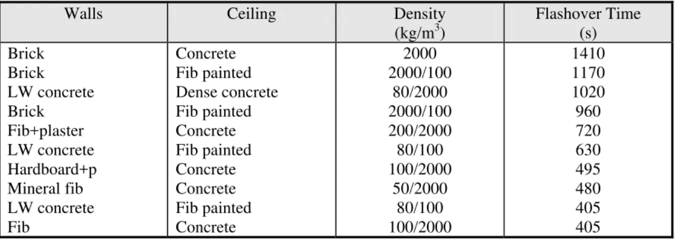
The determination of the time to flashover is very important. As an example of the time to reach flashover and the influence of the construction materials, Table 5.5 shows test results of flashover times for a variety of building materials performed at the Fire Research Station in the U.K. (Malhotra, 1986). The area of the rooms used for the tests was 4.27 m2 and the height was 2.6 m. The rooms were constructed of brick walls with a concrete roof. As a fire source, mock-up timber furniture was provided as for a living room giving a fire load of 24 kg/m2. In addition, the rooms were provided with a wood floor and the walls and ceilings were lined with a variety of materials.
5.3.5 Post-flashover - fully-developed fires
The fully-developed fire stage occurs after flashover. It is characterized by very high temperatures and heat release rates. Once the fire is fully developed, the elements of a building structure must have the necessary fire resistance to prevent spread of fire and eventual structural failure. This stage is of prime importance when trying to satisfy the objective of property protection as well as when considering stability of the structure and the likelihood of fire spread to adjacent properties.
There are two control mechanisms during fully-developed fires: ventilation control and fuel control. The governing mechanism is the one that yields the lower value of rate of heat release. For ventilation-controlled fires, the rate of heat release is dependent upon the available ventilation, ventilation changes (e.g., glass breakage), shape and location of ventilation openings, thermal characteristics of the compartment and the nature of the fuel. In this case, the burning rate is controlled by limiting the supply of oxygen. On the other hand, fuel-controlled fires are affected by the nature of the fuel, surface area of exposed fuel, dimension and thermal characteristics of the compartment. In this case, the burning rate is influenced by the combustible contents, separation of fuel by barriers and the action of making the fuel less likely to burn.
Table 5.5. Flashover times in room fires (Malhotra, 1986)
Walls Ceiling Density
(kg/m3) Flashover Time (s) Brick Brick LW concrete Brick Fib+plaster LW concrete Hardboard+p Mineral fib LW concrete Fib Concrete Fib painted Dense concrete Fib painted Concrete Fib painted Concrete Concrete Fib painted Concrete 2000 2000/100 80/2000 2000/100 200/2000 80/100 100/2000 50/2000 80/100 100/2000 1410 1170 1020 960 720 630 495 480 405 405 Fib = fibre insulation board
LW = light weight concrete +p = with a paint finish
The heat release rate of fully-developed fires can be calculated for the ventilation-controlled fires and fuel-ventilation-controlled fires and the lesser of the two used for design
purposes. The following formula can be used for the calculation of the steady rate of heat release, Q:
Q H= mf c
•
⋅ (5.17)
where: Hc = calorific value of combustible material or heat of combustion, kJ/kg (see Equation (5.18) below and Table 5.6 for some values);
mf
•
= mass loss rate of fuel burning computed as shown below, kg/s.
Hc = Hd ⋅(1 − 0 01. ⋅ M) − 0 025. ⋅M (5.18) where: Hd = calorific value of the dry material, MJ/kg;
M = moisture content in percentage by dry weight.
For ventilation-controlled fires, the mass loss rate of the fuel can be computed using: m A A W H H f T o w comp o o • ⋅ ⋅ ⋅ = .0 02 ( - ) A 0 5. (5.19)
where: Ww = width of the wall containing openings, m; Hcomp = height of the compartment, m.
The mass loss rate can also be calculated using an alternative formula as follows:
m = . A H valid for r g A H A . f o o o 1/ 2 o o 1/ 2 f • ⋅ ⋅ ⋅ ⋅ < 0 092 0 235 (5.20)
where: Af = area of the compartment floor, m2.
For fuel-controlled fires, the fuel mass loss rate can be computed using:
m L t f f • = ∆ (5.21)
where: L = fire load, kg;
∆tf = effective fire duration (a value of 1200 s may be used in the absence of data), s.
5.3.5.1 Fire compartment temperatures
Maximum compartment temperatures can be used to estimate impacts and
consequences of fully-developed fires. The maximum compartment temperature can be determined as follows (Law, 1983):
Tg- T o = ⋅ − e ⋅ − e − − 6000 1 1 0 10 0 5 0 05 ( ) ( . . . Ω Ψ Ω ) (5.22) with Ω = − ⋅ A A A H T o o o
[
]
Ψ = ⋅ − L Ao (AT Ao) 0 5.where: Tg = maximum expected compartment temperature, K; L = fire load (wood), kg.
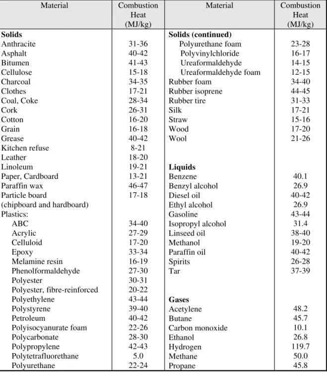
Table 5.6. Calorific values of typical combustible materials (Buchanan, 1994)
Material Combustion Heat (MJ/kg) Material Combustion Heat (MJ/kg) Solids Anthracite Asphalt Bitumen Cellulose Charcoal Clothes Coal, Coke Cork Cotton Grain Grease Kitchen refuse Leather Linoleum Paper, Cardboard Paraffin wax Particle board
(chipboard and hardboard) Plastics: ABC Acrylic Celluloid Epoxy Melamine resin Phenolformaldehyde Polyester Polyester, fibre-reinforced Polyethylene Polystyrene Petroleum Polyisocyanurate foam Polycarbonate Polypropylene Polytetrafluorethane Polyurethane 31-36 40-42 41-43 15-18 34-35 17-21 28-34 26-31 16-20 16-18 40-42 8-21 18-20 19-21 13-21 46-47 17-18 34-40 27-29 17-20 33-34 16-19 27-30 30-31 20-22 43-44 39-40 40-42 22-26 28-30 42-43 5.0 22-24 Solids (continued) Polyurethane foam Polyvinylchloride Ureaformaldehyde Ureaformaldehyde foam Rubber foam Rubber isoprene Rubber tire Silk Straw Wood Wool Liquids Benzene Benzyl alcohol Diesel oil Ethyl alcohol Gasoline Isopropyl alcohol Linseed oil Methanol Paraffin oil Spirits Tar Gases Acetylene Butane Carbon monoxide Ethanol Hydrogen Methane Propane 23-28 16-17 14-15 12-15 34-40 44-45 31-33 17-21 15-16 17-20 21-26 40.1 26.9 40-42 26.9 43-44 31.4 38-40 19-20 40-42 26-28 37-39 48.2 45.7 10.1 26.8 119.7 50.0 45.8 5.3.6 Decay
After reaching a peak burning rate during the fully-developed fire, this rate decreases as the fuel is consumed and the fire fails to spread to neighbouring
compartments. This is the start of the decay stage. Fire decay can also occur from the effects of suppression systems. In the case of fuel consumption without suppression systems intervention, the transition to the decay stage is generally assumed to have started when 80% of the fuel has been consumed by the fire. The heat release rate, Q(t), as a function of time, t, in a linear relationship, can be estimated as:
Q(t t t od fb ) = - .⎛1 1 75 ( - t ) Q ⎝ ⎜ ⎞ ⎠ ⎟ max (5.23)
where: tfb = duration of fully developed burning, s; tod = time of onset of the decay phase, s;
Qmax = heat release during fully developed burning phase, kW.
5.4 Input and Output for The Evaluation Procedures
Tables 5.7 and 5.8 summarize the input and output requirements for fire growth.
Table 5.7. Input requirements
Input Needed SectionTaken From
Possible fire scenarios - Initial design parameters
- Statistics on fires start, fuel arrangement etc.
Nature of building contents - Initial design parameters
Arrangements of fuel in the compartments - Initial design parameters
Effective fire load - Initial design parameters
Compartment geometry - Initial design parameters
Size and location of ventilation openings - Initial design parameters
Thermal characteristics of linings - Initial design parameters
Ambient conditions inside the compartment - Initial design parameters
Wind conditions - Initial design parameters
Volume of smoke produced - Smoke spread
Change in ventilation through the creation of new openings
- Fire spread
- Fire resistance of barriers and glazing
Starting of suppression systems - Initial design parameters
- Fire detection and suppression
Starting of fire fighting activity - Fire detection
- Fire department response
Hot layer temperature - Smoke spread
Table 5.8. Output requirements
Heat release rate - Smoke spread - Fire Spread
- Fire fighting control of the fire
Production of toxic gases (CO) - Smoke spread
- Evacuation (measure of untenable conditions)
Production of smoke - Smoke spread
Flame height - Flame detector response
- Fire spread
- Impact on structural elements
Plume temperature - Heat detector response
- Smoke detector response
- Measure of untenable conditions
Compartment temperatures - Heat detector response
- Structural resistance
- Evacuation (measure of untenable conditions)
Flame emissivity - Fire spread, barrier failure
Entrained mass flow rate in plumes - Smoke spread
Time of occurrence of flashover - Fire fighting response
5.5 Performance Criteria
In order for a fire safety design to be satisfactory, it must be judged against some acceptance or performance criteria. The minimum performance criteria are those established by the National Building Code (1995) and National Fire Code (1995) of Canada. The performance criteria can also be set by the fire safety design team based on the minimum performance criteria found in the National Building Code (1995) and National Fire Code (1995) of Canada.
5.5.1 Minimizing ignition and fire occurrence
To minimize ignition and prevent fire occurrence, it is necessary to address one or more of the following requirements:
1. Identify and remove/minimize the heat sources, 2. Identify and control the fuel ignition characteristics,
3. Identify and minimize/control the interactions between the fuel and the heat sources.
5.5.1.1 Ignition/heat energy sources
Ignition/heat energy sources may be small, however, they may produce sufficient energy to ignite a fuel and start a fire, provided the environment is satisfactory. Many heat and ignition sources may be found in a building including static sparks, hot surfaces,
open flames/burner flames, electrical wiring, smoking, explosives/fireworks, fuel-powered equipment, chemical reactions, welding, and overheated materials (see also Appendix C for more details on ignition sources). To prevent ignition, these sources must be either controlled, isolated or removed.
5.5.1.2 Fuel ignition characteristics
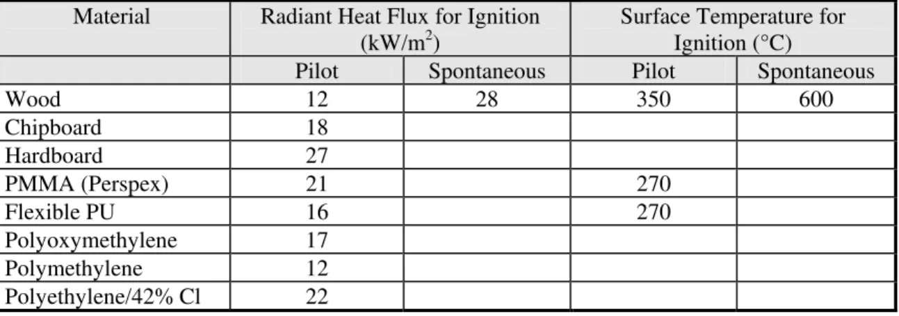
The ignition of combustible materials is mainly affected by the radiant heat flux and surface temperature of the fuel. The BSI Draft Code of Practice (1994) identifies typical threshold values for ignition in terms of the radiant heat flux or surface
temperature, for a variety of materials, as illustrated in Table 5.9. These proposed values can be used, as ignition criteria, to examine the possibility of ignition of a first item. Thus, knowing the ignitability of combustible materials in a compartment, the size of possible heat sources can then be limited to ensure no ignition.
To facilitate the process of determining the ignition criteria, solid fuels can be classified based on their ease of ignitability into groups such as those used by the National Fire Protection Research Foundation (NFPRF) Fire Risk Assessment Method (FRAM) (Bukowski et al, 1990). The proposed classification is shown in Table 5.10. The ignition sources are then limited to below the nominal values of the group
representing the materials in a compartment.
Table 5.9. Threshold values for ignition (BSI, 1994)
Material Radiant Heat Flux for Ignition
(kW/m2)
Surface Temperature for Ignition (°C)
Pilot Spontaneous Pilot Spontaneous
Wood 12 28 350 600 Chipboard 18 Hardboard 27 PMMA (Perspex) 21 270 Flexible PU 16 270 Polyoxymethylene 17 Polymethylene 12 Polyethylene/42% Cl 22
Table 5.10. Heat flux range for ignitability (Bukowski et al, 1990)
Ignitability Heat Flux Range (nominal value)
(kW/m2)
Easy ≤ 14.1 (10)
Hard > 28.3 (40)
5.5.1.3 Fuel/heat sources interactions
Ignition can be prevented by minimizing or removing, if possible, the interaction that may exist between a fuel and a heat source. The effectiveness of ignition prevention measures is affected by many factors, including fire safety management procedures, processes undertaken such as welding, chemical processing and experimentation, and storage and dispensing of hazardous materials, equipment in place such as furnaces and portable heating units, and nature of contents of a compartment.
The potential causes of fuel/heat sources interactions can be grouped into two groups:
1. Occupant-related interactions which include child play, cooking, heating, smoking, fuel spills, misuse of heat sources and misuse of fuel.
2. Non-occupant-related interactions which include arson, equipment deficiency such as non-properly insulated electrical wiring, operational deficiency such as the lack of appropriate fire safety policies, process failure such as leakage of stored hazardous material, and exposure/natural fire.
Minimizing or controlling the interaction between fuel and heat sources can be accomplished through a number of ways, including the following:
• Proper arrangement of equipment that produce heat,
• Control of the temperatures generated by the heat-producing equipment, • Control of gases generated by the heat-producing equipment,
• Control of fire properties of combustible building materials,
• Conducting periodic inspection and maintenance of heat-producing equipment, • Establishment and enforcement of in-house fire safety rules,
• Education of occupants in fire safety,
• Implementation of maintenance and good housekeeping measures, • Implementation of an effective waste management program, • Safeguarding fire risk areas from arson and vandalism,
• Separation between fuel and heat sources either by a distance or a physical barrier. 5.5.2 Control of fire growth
A fire can be controlled if the components influencing its growth are controlled. A first approach is to limit fire growth by specifying the appropriate materials to cover the walls, floors and ceiling, especially in the escape routes so that material ignitability is delayed in the compartment of fire origin. Table 5.9 provides ignition criteria which can be used to determine the ignition of neighbouring items. These threshold values for