Publisher’s version / Version de l'éditeur:
Journal of the Acoustical Society of America, 101, February 2, pp. 964-969,
1997-02-01
READ THESE TERMS AND CONDITIONS CAREFULLY BEFORE USING THIS WEBSITE. https://nrc-publications.canada.ca/eng/copyright
Vous avez des questions? Nous pouvons vous aider. Pour communiquer directement avec un auteur, consultez la première page de la revue dans laquelle son article a été publié afin de trouver ses coordonnées. Si vous n’arrivez pas à les repérer, communiquez avec nous à [email protected].
Questions? Contact the NRC Publications Archive team at
[email protected]. If you wish to email the authors directly, please see the first page of the publication for their contact information.
NRC Publications Archive
Archives des publications du CNRC
This publication could be one of several versions: author’s original, accepted manuscript or the publisher’s version. / La version de cette publication peut être l’une des suivantes : la version prépublication de l’auteur, la version acceptée du manuscrit ou la version de l’éditeur.
Access and use of this website and the material on it are subject to the Terms and Conditions set forth at
Sound transmission through a double leaf partition with edge flanking
Craik, R. J. M.; Nightingale, T. R. T.; Steel, J. A.
https://publications-cnrc.canada.ca/fra/droits
L’accès à ce site Web et l’utilisation de son contenu sont assujettis aux conditions présentées dans le site LISEZ CES CONDITIONS ATTENTIVEMENT AVANT D’UTILISER CE SITE WEB.
NRC Publications Record / Notice d'Archives des publications de CNRC:
https://nrc-publications.canada.ca/eng/view/object/?id=cf736972-9886-4cda-b072-1b01e3e7cc9f https://publications-cnrc.canada.ca/fra/voir/objet/?id=cf736972-9886-4cda-b072-1b01e3e7cc9f
http://www.nrc-cnrc.gc.ca/irc
Sound t ra nsm ission t hrough a double le a f pa rt it ion w it h e dge
fla nk ing
N R C C - 4 1 5 0 1
C r a i k , R . J . M . ; N i g h t i n g a l e , T . R . T . ; S t e e l , J . A .
F e b r u a r y 1 9 9 7
A version of this document is published in / Une version de ce document se trouve dans:
Journal of the Acoustical Society of America, 101, (2), February, pp. 964-969,
February 01, 1997
The material in this document is covered by the provisions of the Copyright Act, by Canadian laws, policies, regulations and international agreements. Such provisions serve to identify the information source and, in specific instances, to prohibit reproduction of materials without written permission. For more information visit http://laws.justice.gc.ca/en/showtdm/cs/C-42
Les renseignements dans ce document sont protégés par la Loi sur le droit d'auteur, par les lois, les politiques et les règlements du Canada et des accords internationaux. Ces dispositions permettent d'identifier la source de l'information et, dans certains cas, d'interdire la copie de documents sans permission écrite. Pour obtenir de plus amples renseignements : http://lois.justice.gc.ca/fr/showtdm/cs/C-42
T. R. T. Nightingale
Acoustics Laboratory, Institute for Research in Construction, National Research Council Canada, Ottawa,
OntarioKIA OR6,.Canada
Sound transmission through a double leaf partition
with edge flanking
R.
J.
M. CraikDepartment of Building Engineering and Surveying, Heriot- Watt University, Riccarton, Edinburgh
EH14 4AS. United Kingdom
J.
A.
SteelDepartment afMechanical and Chemical Engineering, Heriot-Wart University, Riccarton, Edinburgh
EH144AS, United Kingdom
(Received 8 January 1996; revised 2 September 1996; accepted 24 September 1996)
Lightweight double leaf partitions are widely used and with proper design give good sound isolation. However, when these walls are used as party walls between dwellings, then precautions are necessary to prevent the transmission of fire and smoke. This is usually carried out by placing a firestop in the cavity. This firestop introduces flanking transmission paths reducing the airborne transmission loss of the wall. A simple model is developed which can predict vibration transmission across this type of structural connection. The structural vibration transmission loss can then be used with a more general statistical energy analysis model to give the sound transmission through the entire system. Predicted airborne transmission loss results for a variety of different materials are compared with measured results and good agreement is obtained. © 1997
Acoustical
Societyof
America.
[SOOOI-4966(97)01002-3]PACS numbers: 43.55.Ti, 43.55.Rg, 43.55.Vj [JDQ]
©1997 Acoustical Society of America 964
I. THEORY OF STRUCTURE-BORNE TRANSMISSION by laboratory measurements made on standard forms of
construction.2
In this paper a model is developed which enables the vibration transmission across a continuous firestop to be pre-dicted. The predicted structural transmission loss results from this model are then used within a more general statis-tical energy analysis framework. This enables noise trans-mission between the two rooms through the partition system and also across the fires top to be determined.
A comparison. of measured results with these calcula-tions shows good agreement. Itis shown that there are con-siderable differences in sound transmission depending on which firestop materials are used and that this difference can be predicted. The model enables appropriate fires top materi-als to be selected.
The actual construction of the joint between the two leaves of the wall and the two parts of the floor at the firestop is complex and some simplifications are necessary if useable models are to be developed. A floor will usually consist of wood joists with a floor covering (typically a plywood deck) and a gypsum board ceiling. Each leaf of the wall will gen-erally have a metal or wooden frame with gypsum board covering. For simplicity, the effects of the joists in the floor and the frame in the walls have not been considered. Their omission greatly simplifies the calculation but can lead to
some errors.
In the test structure the frame reduced vibration propa-gation across both the gypsum board wall and the plywood
0001-49661971101 (2}1964161$1 0.00
Double walls are widely used both as internal partitions and as high performance walls separating two different dwellings. They normally consist of a frame of wood or pro-filed metal channel covered with one or more layers of gyp-sum board. If the wall is to have good sound isolating prop-erties, then there will usually be sound absorbing material in
the cavity whichwillincrease the airborne transmission loss.
Sound insulation will be further improved if two separate frames are used to support the gypsum board so that there is no physical connection between the two leaves of the wall. It is these high performance walls that are considered in this paper.
When properly designed these partitions work well and give good sound isolation. However, in walls that separate dwellings, fire and smoke must also be considered as the cavity can allow the spread of fire throughout the dwelling. To prevent this, a physical bartier called a firestop is usually placed in the cavity as shown in Fig. 1. Typical materials used are plywood, gypsum board, or steel.1 When the
firestop is at floor level (as shown in Fig. 1) the simplest method of construction is to make the plywood floor deck continuous under the wall. When the fires top is a vertical edge (in which case Fig. 1 is a plan rather than a section and the floor is another wall), then the gypsum board that covers the flanking wall can be continuous across the cavity of the separating wall.
Measurements made in real buildings show that the air-borne transmission loss of a wall when a fires top has been fitted is less than when there is no firestop. This is confirmed
964 J.Acous!. Soc. Am. 101 (2), February 1997
(6)
-jf----..
xo
2 3 0,---11-o
zo
knis the near-field wave number in thex orz direction and can be found for any plate from'
The requirement that the displacement of all the plates be zero at the bound31y (where
x
andz
=0) gives, from Eqs. (1)-(4),Craik et a/.:Sound transmission with edge flanking 965
wherek is the wave number.
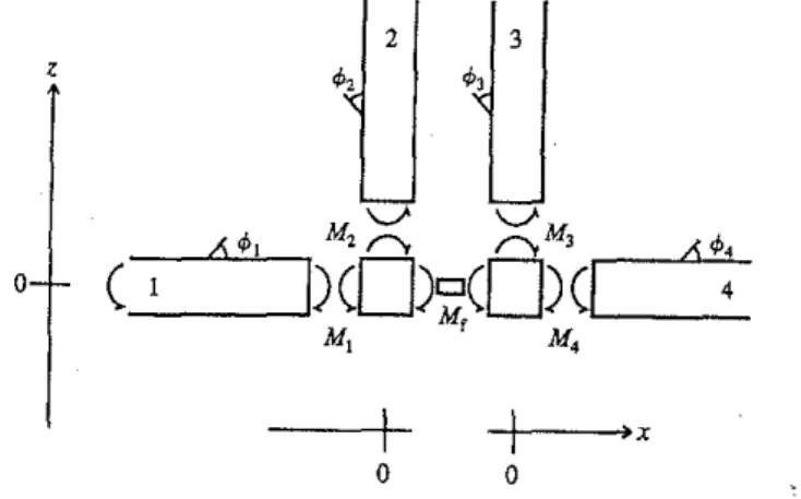
Since power is transmitted only by moments in this model the orientation of the plates can be changed without affecting the structural transmission loss. Thus, the number-ing can be changed so that plate 1 is the wall and plate 2 is the floor. The only necessary assumption is that plates I and 2 are on one side of the fires top and that 3 and 4 are on the other.
If the sound field on plate I is diffuse then all angles of incidence are possible. For a given angle of incidence 8, (measured from the nOm1al) on plate I the angle of transmis-sion of the other waves can be found from the relationship
k, sin 8,=k, sin 8,=k, sin 83=k4sin 84 , (5)
bending wave with amplitude T and a near-field bending wave with amplitude Tn. In addition on plate I there is as-sumed to be a wave incident on the joint with unit amplitude. The displacement on plates 1-4 (" to ,,;; can then be given as
Xe-ikjsin81Yeiwl, (1)
セR]HtR・MゥォR cos(}2Z+Tnze-kIl2Z)e-ik2 sin (J2Yeiwt, (2)
g3
=
(T3e - ik) cos B3z+Tn3 e -kn3Z)e -ik 3 sin {J3Y e iwt , (3) g4=(T4e-ik4 cos114x+ Tn4e-kI14X)e-ik4 sin 84Yeiwl, (4)FIG. 2. Coordinate system used to calculate the structural transmission loss.
1+ T,
+
T" =T,+ T",= T,+ T'3= T4+
Tn4=0, (7)so that the amplitude of the near-field waves can be given in tem1S of the traveling wave amplitude for each plate.
At the boundary it is assumed that the plates on the left of the joint and those on the right are rigidly bonded together so that the angle between them is preserved. This leads to two equations linking the slope,
<p,
on plates Iand 2and theROOM 2
2 layers of 13 mm gypsum board on either side of wood studs at 400mm centreswith 2 layers of 90mm cavityabsorption
16mmplywooddeck on
38 x 235 mm joist!l
gypsum board ceiling WALL firestop nominalwidth 25mm 2 layers of 90 mm cavity absorption ROOMl FLOOR
965 J. Acoust. Soc.Am.,Vol. 101, No.2, Februa", 1997
floor. If a panel is excited by airborne sound then the vibra-tion energy will be unifom1ly distributed across the panel and there will be no net power flow between different sec-tions so that the effect of the frame will be negligible. How-ever, in flanking paths the excitation of the receiving room wall and floor is along an edge. In this case the effect of the frame and the joists will be more important. In the test con-structions the joists were parallel to the test joint and so affected the propagation of energy away from the joint. In the walls (both the common wall and the flanking wall) the frame members were vertical. If the fires top element is at floor level then the wall frame will have a small effect on the distribution of energy across .the panel. If the fires top is a vertical edge then the effect will be larger.
Another approximation that simplifies the calculations is to ignore in-plane vibration. Where a floor and a wall meet at a right angle it is reasonable, as a first approximation, to assume that each will prevent lateral motion of the other. Thus, the floor will prevent in-plane motion of the wall that is at right angles to it and vice versa. The wall and floor are still free to rotate bnt there is no lateral motion of the actual joint. This assumption prevents the generation of in-plane displacements and power is then transmitted by moments only. With these assumptions the structural transmission at the joint can be determined.
The parameter used to describe transmission is the trans-mission coefficient, T, defined as the ratio of the power trans-mitted acrOss a joint to the power incident on it. This is then related to the structural transmission loss, H= 10 10g(IIT).
The method commonly used to determine the structural transmission loss at the joints between plates is to examine the behavior of semi-infinite plates connected at a joint3 In this case there are four plates (two walls and two floors). It is assumed that there is a bending wave incident on the joint and that the objective of the analysis is to calculate the am-plitude of the waves leaving the joint and hence the struc-lural transmission loss. This is a standard procedure for cal-culating structural transmission108s.3.4
The general coordinate system used for the calculations is shown in Fig. 2. On each plate there will be a traveling
FIG. 1.Section through a double wall resting on a wood floor with a firestop to prevent the passage of fire and smoke.
f ) 1 1 e 1 s
slopes on plates 3 and 4. Equating the slopes on plates I and 2 gives <pj
=
¢,.
Expressing the slope as the derivative of the displacement' gives。セェ 。セR
ax
=---y;.
Evaluating this at the origin wherex, andz
=
0 givesTj[-kaj+ik j cos OJ]+T,[-ka,+ik, cos 0,]
(8)
(9)
sumptions that have been made. Thereforeinall calculations the simple approximation of Eq. (IS) has been used.
Inserting Eqs. (14) and(16)into Eqs. (12)and(13),and substituting for the displacement, gives the two moment equations as Tj[2Bjk;+Bfk,jld-iBrkj cos oェャ、}KtL{MRbLォセ} +T,[Bfk",ld-iBfk, cos 041d] =-2Bjk;-Btkalld-iBfkj cos 0lld (17) (10) (19)
Similarly, equating the slopes of plates 3 and 4, so that
<p,
=
<p" gives。セL 。セL
---y;=
""j;'
which can be given as
T,[kn,-ik, cos O,]+T,[-k"4+ik, cos 0,]=0. (11)
Two other equations can be written relating the mo-ments. Summing the moments about each side in tum and
using the coordinate system shown in Fig. 2 gives
(12)
and
Tj[Bfknjld-iBfkj cos oェャ、}Ktj{Rbjォセ}
KtL{RbLォセKbヲォ。Lャ、MゥbヲォL cos O,ld]
=-Btknjld-iBfk j cos Ojld. (18)
The four equations, (9), (11), (17), and (18), can be solved numerically to give the amplitude of the waves leav-ing the joint from which the structural transmission coeffi-cient r can be found using
p"kj cos
o,IT,I'
rd
0)=
p,jk, cos OJ s s 1 1 rr
a L n p tl ft d e Co
(rIt
966 (20)Craik et al.:Sound transmission with edge flanking
j
セQRr av
=
0 r(O)cos 0dO.where P, is the surface density.
The angular averaged transmission coefficient can then be found fromJ
As the four plates that make up the joint are often very similar a useful approximation is to assume that all the plates are made from the same materials and have the same thick-ness.Inthis case, the normal incidence solution for the
struc-tural transmission loss can be given as
This can be used to give an estimate of the structural trans-mission loss and can be used to quickly rank different
mate-rials.
The relation between the parameter B kdlBf and the
structural transmission loss can be seen -in Fig. 3 for the case
where all four plates are assumed to have the same material properties. The results show both the random incidence so-lution and the normal incidence approximation. It can be seen that the normal incidence approximation is about 2 dB
less than the random incidence solution. At low frequencies
or for stiff firestops (the left of Fig. 3) the structural
trans-mission loss tends to a constant value. The limits are 9 dB
for the normal incidence solution and 10.8 dB for the random
incidence solution and are the same as the result for a rigid
cross joint. As the frequency iucreases or the stiffness gets
less so the structural transmission loss increases.
The solution given above is for four plates connected at a joint. In some cases there may be additional plates i!' !Jl"
example the walls under the floor were included. For ea,11
(13)
(14)
(16)
J.Acoust. Soc. Am., Vol. 101, No.2, February 1997
{
。Gセ
。Gセ}
M=-B
a;r+/"
J?'
so that, by substituting the displacement into Eq. (14) and evaluating at x, y and z=O, the moment due to eacb plate
can be found. For moments on plates 2 and 3 the
x
depen-dence in Eq. (14) is changed toz.
Here, B is the material stiffness per unit width and is given in terms of Young's modulus E, the thickness h, and Poisson's ratio /", asEh'
where Mi is the moment acting on the firestop from plate i and M f is the moment acting on the plates due to the firestop. The moment (per unit width) acting on the boundary due
to wave motion on a plate can be given by3
The moment (per unit width) acting on the plates due to the firestop can be written in terms of the change in slope across its width (<pj - <P4) and the stiffness (per unit width) of the firestop component. This depends on both the stiffness of the firestop materialBf and the cavity depthd to give
B
fMf=d (<pj- <p,),
where d, the width of the firestop, is taken as the separation between the sole plates of the wall (25 mm for the test struc-ture). At normal incidence the bending stiffness of the fir-estop can be found from Eq. (15). At other angles of inci-dence there also will be bending along they axis which will
increase the overall stiffness. Accounting for this more
cor-rectly would increase the overall complexity of the model and is not justified, given the other approximations and
18 19 20
1
-I \'"
I \ I)r
0.> I,
I ,<. I I\/
I
1\
"'"
\ I I I \ ¥I
\\
I\
'" 0.2 Nセ I セJ
I \'.
.'\---... I I 0 8..
'"
\ I1
0.1 \ \ セ セ,
0.05...1·':0:.:
V...
63 125 250 500 1000 '000 4000 Frequency Hz I I I / / / / ,-, / , / 17 10 セ 16 セ セ 15 gi
I' セ 13セ
l'
セ ャャセMMMMMM
-9セ][[]ウ]GM]M⦅⦅Z⦅ッZZ⦅⦅⦅⦅ZlMMBGZMMMlMMMMMャ 0.01 0.02 0.05 0.1 0.2 0.5 BkdlBr
!os
7) :) eFIG. 3. Structural transmission loss between plates land 3 (or 4) at ajoint where all the plates are made from the same material and have the same thickness.- - , random incidence; ----, normal incidence.
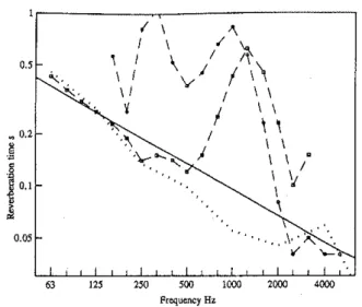
FIG. 4. Reverberation time measured in the cavity of the double wall and floor. --0--, measured in the wall; --0--, measured in the floor; - - , estimated curveSOセヲ[ ,measured in an isolated cavity.
additional plate there is one additional equation relating the slope of the new plate to an existing plate and one additional
term in oneof the moment equations.
II. TEST FACILITY
In order to test the theory given in the previous section
measurements were carried out in the flanking lahoratory of the National Research Council of Canada.' The test facility consists of four rooms (two up and two down) with volumes from 35 to 50 m'. The test joint shown in Fig. I formed the only link hetween two pairs of otherwise separate rooms. The walls were made from wood frames covered with two layers of gypsum board and the floors were constructed from 38- X235-mm joists with 16-mm plywood on the top and 2 layers of 13-mm gypsum board on the ceiling attacbed using resilient funing strips. The separating wall (13.5 m') had independent frames with two layers of plasterboard on each side and the cavity between the two leaves was filled with sound absorbing material.
Sound transmission was measured between the upper
pairs of rooms and the firestop was either at floor level or at a wall edge. When the firestop was at floor level the joint is like that shown in Fig. I, except that there are rooms under-neath. Due to the method of construction it was not appro-priate to include the walls below the floor in the analysis, as there was no significant physical connection between the floor assembly and the lower party wall.
Sound transmission between the test rooms was pre-dicted using a statistical energy analysis model. Statistical energy analysis modeling is described in more detail by Craik4and details of the model used are given in Ref. 5.
The fires tops used were all 25 mm wide and were 0.38-mm steel, 16-mm plywood or 26-mm gypsum board (made from 2 sheets of 13-mm gypsum board).
III. RESULTS
All of the tests carried out were of airborne sound trans-mission between two rooms separated by a test wall, as
shown in Fig. I but with additional rooms underneath. A
noise source was placed in room 1 and a standard sound
· · 6 ·
transmiSSIOn test was earned out to give the airborne
trans-mission loss of the wall.
The first tests were carried out when there was no fir-estop connecting the two leaves of the separating wall so that direct transmission through the wall together with any minor flanking paths through the rest of the laboratory could be determined.
As the dominant transmission path is the direct path through the wall, the absorption in the cavity is important. Transmission through the double wall can be considered as
transmission into the cavityfollowed bytransmission out of
the cavity. The sound-pressure level in the cavity is inversely proportional to the cavity damping so that the overall
air-borne transmission loss is inversely proportional to the
rever-beration time of the cavity.
The reverberation time,T,that was measured in the wall cavity and in one of the floor cavities can be seen in Fig. 4. The reverberation time was much less than would be ex-pected for a normal room and was very difficult to measure. A standard decay rate method was used with a small loud-speaker placed in the cavity. There was considerable inter-ference in the cavity decay curve from energy returning from the rooms and the rest of the structure making the decay curves difficult to interpret. It was assumed that the high readings of around 0.5 s were due to the reverberation time of the rooms and that the true reverberation time was the lowest of the measured readings. A best fitting estimate of
T= 3/dwas therefore used as this passed through the lowest
readings. Subsequent measurements were made on an
iso-lated test structure that reproduced the conditions in the cav-ity without interference from any surrounding structure. The results for the isolated cavity (also shown in Fig. 4) confirm that the estimate is a good one.
Using these data and a standard SEA model, sound transmission through the basic partition was predicted. This is shown together with the measured airborne transmission loss in Fig. 5. It can be seen that there is good agreement
125 250 500 1000 2000 4000 FrequencyHz 80 80 ,-70 / '0 セ
' -
,-セ Lセ•
60 / セVo セ /•
] S g 50 I'v·Lo
"
i
I 'J
I!
40 1r
< J 30 J 30 I 20 20 63 125 2" '00 1000 21l1J() 41l1J() 63 Frequency HzFIG. 5. Airborne transmission loss of a double wall with no firestop. A simplified SEA model is shown in the insert. - - , predicted; ----, measured.
between the measured and predicted data, although the pre-dicted dip at around 3 kHz associated with the critical fre-quency is not at the correct frefre-quency. The SEA model used included all of the surrounding structure (using 20 sub-systems) and is therefore more complex than the 5 subsystem model shown in the insert. However, the5subsystem model describes the direct paths through the partition and is suffi-cient for most purposes. In the SEA model the arrows from the room to the cavity represent the nonresonant (mass-law)
transmission path and will dominate transmission at
frequen-cies below the critical frequency.
Using the 5 subsystem model the airborne transmission loss due to the direct path can be given as4
fr, fr,
ar
fll 6, di th hi th thw,
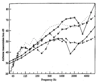
ca at w: ex in tn flc tic flc pr or th ar fll su be es m FI wi ra, su 'I 968 Craiket al.: Sound transmission with edge flankingFIG. 6. Airborne transmission Joss for a· wall with a steel and a plywood firestop at floor level. --0--, measured with a steel firestop;- - 0 - , predicted with a steel firestop; --0--. measured with a plywood firestop;
- - 0 - ,predicted with a plywood firestop; measured with no firestop.
RolNjZMGMMMlZAMZMjNNNjMZMャMMlNNjNNNNLgMNlMMlNNjNNNNLNjNNLNLlNlNMGMセjMNj
63 125 250 500 1000 2000 4000
Frequency Hz
results that are more or less the same as the results for no
firestop. The results for the plywood firestop show a signifi
cant decrease in airborne transmission loss at the higher
fre-quencies. This result shows that the best method of reducing flanking is to use a flexible firestop such as a thin steel plate. An analysis of the different transmission paths
associ-ated with transmission between the two rooms when there is
a plywood firestop can be seen in Fig. 7. The figure shows the predicted airborne transmission loss when there is no firestop together with the four main paths associated with the firestop. The least important is the path from source room to the wall in the source room across the firestop to the wall in the receiving room followed by radiation into the receiving room. The most important of the flanking paths is from the
source room, into the floor of the source room, across the
joint into the floor of the receiving room, followed by radia-tion into the receiving room. The other two flanking paths
80
FIG. 7. Transmission paths associated with the plywood firestop. - - . sum of all paths; --0--, wall-wall path; MセoセセL wall-floor flath; --0--, floor-wall path;セM「LGZGGGZGL ftoor-fioorpath; ... , predici:;; with no firestop.
(22)
J. Acoust. Soc. Am" Vol. 101, No.2, February 1997
I
R=R1+R,+lOlog fTc +14.4,
where R is the overall airborne transmission loss, R1,2is the
airborne transmission loss of the individual leaves of the wall and can be approximated to the mass-law equation' below the critical frequency, andT, is the reverberation time of the cavity. This equation assumes that the cavity is sufficiently narrow that it behaves as a two dimensional space.
f
is the band center frequency (usually±
octaves).When the firestop is introduced then sound is transmit-ted by additional paths which decrease the overall airborne
transmission loss. The model is then much more complex
and there is no single simple algebraic expression for the sound reduction index equivalent to Eq. (22). Either a full SEA model has to be set up or else a path by path analysis
carried out.4 The results of such calculations can be seen in
Fig. 6, which shows the measured results for no fires top (shown in Fig. 5) together with the measured and predicted
results for situations where there is a steel fires top and a plywood fires top at floor level.
At low frequencies sound is mainly transmitted via the direct paths so that the additional flanking paths through the firestop make little difference. At higher frequencies the re-sults show clearly the effect of the additional flanking paths. The steel firestop provides very weak coupling and gives
80 80 ./ 70 / 70 セセ /' セ , ' ,o;;.,r-c/· . , , ,:-,-;,:,- セ r'.:...; . § 60 ,';0- セVP セ
"
r .;.. セ >' \I
,1'7',,'
\ f. MャvGウBBセ ..-y .9..
--,(,',--I
50 J Lセ 50 .1 I '-"--_If'エNZセI
J
セ
"I!
'.-
;.-セ
40{
J
40i
"
. ; 30セ
30 ./ I I Iw
W 63 125 250 500 1000 2000 4000 63 125 250 500 1000 2000 4000 FrequencyHz Frequency Hz 'ood ,top; 1no ·ws no the to in 109 the the ゥ。セ ths-.
th; ithFIG. 8. Airborne transmission loss for transmission between the two rooms when a floating floor is placed over the floor to reduce excitation of and radiation from the floor. " measured with no firestop; --0--, mea-sured with a plywood firestop and a floating floor; --6.--,measured with a plywood fires top; - - , predicted.
from the source room wall to the receiving room floor and from the source room floor to the receiving room wall are approximately equal and lie midway between the other two flanking curves. As was shown in the measured data in Fig. 6, the transmission at low frequencies is dominated by the direct path through the wall. In this figure the prediction for the wall with no fires top is shown for comparison. At the higher frequencies, above about 125 Hz, the dominant path is the flanking path involving transmission from one floor to the other and shows clearly the effect of this path on trans-mission between the two rooms.
Given that the dominant flanking path involves the floor in each room then one method of improving the overall transmission loss between the two rooms would be to place a floating floor on top of the structural floor to reduce excita-tion of the floor and radiaexcita-tion from it. The results for such a fioor can be seen in Fig. 8. This shows the measured and predicted results for the case where there is a floating floor on the receiving side only. For simplicity it was assumed that the floating floor only eliminated coupling between the floor and the room (effectively eliminating two of the four main flanking paths). The predicted results are lower than the mea-sured results but both show a significant increase in the air-borne transmission loss compared to that for a plywood fir-estop.
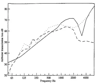
Figure 9 shows results for flanking along the external wall where the fires top was two sheets of gypsum board carried through from the wall of one room to the wall of the other. Again the results are shown for a system with and without a fires top. In this case the fires top has little effect except at the higher frequencies.
FIG. 9. Airborne transmission loss of the double wall when there is a gyp-sum board fires top providing flanking along the external wall. ----, mea-sured; - - , predicted; measured with no firestop.
IV. CONCLUSIONS
Despite the simplicity of the model used for the calcu-lation of structural transmission loss, it gives reasonable agreement between the measured and predicted results. The theory predicts the correct trends and therefore allows a com-parison of the effect of different fires top materials. The ply-wood fires top is the simplest method of forming a fires top at floor level and leads to significant flanking paths for double partition constructions. In the test construction these could be reduced by placing a floating floor on top of the structural floor. Alternatively a thin steel sheet can be used as a firestop to minimise flanking transmission.
An estimate of the structural transmission loss can be found from Eq. (21) which can be used to rank different test materials.
INational Building Code of Canada 1990,Part9, Section 9.10.15 Firestops, Associate Committee on the National Building Code, National Research Council, Canada, 1991.
2T. R, T.Nightingale, "Methods for measuring and identifying flanking transmission in キッッ、セヲイ。ュ・、 constructions," Proc. 1NTERNOlSE 93, 953-956 (1993).
3L.Cremer, M. Heckl, and E.E.Ungar, Structure-Borne Sound (Springer-Verlag, Berlin, 1988).
4R.J. M.Craik, Sound Transmission Through Buildings Usingsエ。エゥセᄋエゥ」。ャ
Energy Analysis (Gower, Aldershot, United Kingdom, 1996).
5R.J,M,Craik, J,A.Steel, and T. R.T.Nightingale, "Sound transmission through framed buildings," IRe internal reportircセirセVWRL Institute for Research in Construction, National Research Council, Ottawa, Canada, 1995.
6ASTM E336-90, "Standard test method for measurement of airborne sound inSUlation in buildings," 1995 (also ISO 140 1978).
7L. L. Beranek andI. L. Ver, Noise and Vibration Control Engineering (Wiley, New York, 1992),