Publisher’s version / Version de l'éditeur:
Vous avez des questions? Nous pouvons vous aider. Pour communiquer directement avec un auteur, consultez la
première page de la revue dans laquelle son article a été publié afin de trouver ses coordonnées. Si vous n’arrivez
pas à les repérer, communiquez avec nous à [email protected].
Questions? Contact the NRC Publications Archive team at
[email protected]. If you wish to email the authors directly, please see the
first page of the publication for their contact information.
https://publications-cnrc.canada.ca/fra/droits
L’accès à ce site Web et l’utilisation de son contenu sont assujettis aux conditions présentées dans le site
LISEZ CES CONDITIONS ATTENTIVEMENT AVANT D’UTILISER CE SITE WEB.
Internal Report (National Research Council of Canada. Institute for Research in
Construction), 1998-03-01
READ THESE TERMS AND CONDITIONS CAREFULLY BEFORE USING THIS WEBSITE.
https://nrc-publications.canada.ca/eng/copyright
NRC Publications Archive Record / Notice des Archives des publications du CNRC :
https://nrc-publications.canada.ca/eng/view/object/?id=04ac8069-a5d2-4038-8787-da064b073e7f
https://publications-cnrc.canada.ca/fra/voir/objet/?id=04ac8069-a5d2-4038-8787-da064b073e7f
NRC Publications Archive
Archives des publications du CNRC
For the publisher’s version, please access the DOI link below./ Pour consulter la version de l’éditeur, utilisez le lien
DOI ci-dessous.
https://doi.org/10.4224/20331556
Access and use of this website and the material on it are subject to the Terms and Conditions set forth at
Gypsum Board Walls: Transmission Loss Data
Gypsum Board Walls: Transmission Loss Data
Halliwell, R.E.; Nightingale, T.R.T.; Warnock,
A.C.C.; Birta, J.A.
IRC-IR-761
National Research
Council Canada
Conseil national de
recherches Canada
Gypsum Board Walls:
Transmission Loss Data
by R.E. Halliwell, T.R.T. Nightingale, A.C.C. Warnock, J.A. Birta
Internal Report IRC-IR-761
March 1998
This project was jointly funded by:
Canada Mortgage and Housing Corporation
Canadian Sheet Steel Building Institute
Cellulose Insulation Manufacturers Association of Canada
Forintek Canada
Gypsum Manufacturers of Canada
National Research Council Canada
Owens-Corning Fiberglas Canada Inc.
Roxul Inc.
Published by
Institute for
Research
Council Canada
Page 1
GYPSUM BOARD WALLS:
TRANSMISSION LOSS DATA
By R.E. Halliwell, T.R.T. Nightingale, A.C.C. Warnock, J.A. Birta
TABLE OF CONTENTS
Introduction ... 3
Measurement of Sound Transmission
Measurement Process ... 4
Precision and Reproducibility ... 5
Experimental Design ... 7
Specimen Installation Details... 8
Gypsum Board Attachment Details... 10
Characteristics of Materials... 14
Individual Specimen Data ... 18
Wood studs – 1 layer gypsum board ... 19
1 + 2 layers gypsum board... 23
2 + 2 layers gypsum board... 26
Steel studs studs – 1 layer gypsum board ... 27
1 + 2 layers gypsum board... 91
2 + 2 layers gypsum board... 122
Wood studs with resilent channels one side... 153
1 + 2 layers gypsum board... 188
2 + 2 layers gypsum board... 215
Steel studs with resilient channels one side ... 231
1 + 2 layers gypsum board... 236
2 + 2 layers gypsum board... 242
Wood studs with resilient channels two sides... 246
1 + 2 layers gypsum board... 248
2 + 2 layers gypsum board... 249
Wood studs with fibre board ... 250
1 + 2 layers gypsum board... 251
2 + 2 layers gypsum board... 253
Wood studs with no insulation... 254
Steel studs with no insulation... 256
Council Canada
Page 2
1 + 2 layers gypsum board... 280
2 + 2 layers gypsum board... 290
Staggered wood studs with resilient channels one side... 297
1 + 2 layers gypsum board... 303
2 + 2 layers gypsum board... 308
Staggered wood studs with resilient channels two side ... 311
Staggered wood studs with no insulation ... 314
Double wood studs ... 316
1 + 2 layers gypsum board... 339
2 + 2 layers gypsum board... 345
Double steel studs... 351
1 + 2 layers gypsum board... 356
2 + 2 layers gypsum board... 359
Council Canada
Page 3
INTRODUCTION
In 1995 the IRC Acoustics Laboratory completed a study of sound transmission through gypsum
board walls. The results were reported in IRC-IR-693, Summary Report for Consortium on
Gypsum Board Walls: Sound Transmission Results but provided only STC ratings.
The project was supported by a consortium including Canada Mortgage and Housing
Corporation, Canadian Sheet Steel Building Institute, Cellulose Insulation Manufacturers
Association of Canada, Forintek Canada, Gypsum Manufacturers of Canada, the Institute for
Research in Construction of the National Research Council Canada, Owens Corning Fiberglas
Canada Inc., and Roxul Inc.
This report represents an extension of IRC-IR-693 by providing detailed one–third octave band
transmission loss data, physical specifications of the materials used, and construction details for
each wall tested. Besides the 285 walls reported in IRC-IR-693, an additional 65 measurements
have been included.
Although some of the specimens were chosen by individual clients to demonstrate the
performance of specific products, these were combined with a structured series established
collectively by the consortium. The combined set of 350 specimens provides the basis for a
broad general evaluation of sound transmission through gypsum board wall systems.
Council Canada
Page 4
MEASUREMENT PROCESS
The acoustical measurements were made in the suite of reverberation chambers in building M-27
of the Institute for Research in Construction of the National Research Council Canada
(IRC/NRCC). Wall specimens were mounted in a removable test frame between the two
chambers, without rigid contact to either reverberation chamber. The wall test opening measured
3.05 m x 2.44 m. The volume of the source room was 65 m
3
. The volume of the adjacent
receiving room was 250 m
3
. Both reverberation chambers were supported on spring vibration
isolators. In addition to fixed diffuser panels in both rooms, the large room also had a rotating
diffuser panel. Test signals were supplied to each room by four loudspeakers with independent
sound sources. Each room had a calibrated condenser microphone (B&K Type 4166, 12.5 mm
diameter) positioned by a computer-controlled robot arm.
Tests were conducted in accordance with the requirements of ASTM E90-1990, Standard
Method for Laboratory Measurement of Airborne Sound Transmission Loss of Building
Partitions, and of ISO 140/III 1978(E), Laboratory Measurement of Airborne Sound Insulation of
Building Elements. The Sound Transmission Class (STC) was determined in accordance with
ASTM standard classification E413-1987.
Measurements were controlled by a desktop PC-type computer interfaced to a Norwegian
Electronics type 830 real time analyzer. Under computer control, the microphones were moved
to nine positions to sample the sound field in each chamber. Sound pressure levels were
measured at each of the nine microphone positions, and combined to get the average sound
pressure level in each room . Five sound decays were averaged to get the reverberation time at
each microphone position in the receiving room; these times were then averaged to get mean
reverberation times for the room. The sound pressure level and reverberation time measurements
were made for all standard one-third-octave-bands from 50 Hz to 6.3 kHz. These data were then
used to calculate sound transmission loss (TL) for each frequency band as specified in ASTM
E90.
Council Canada
Page 5
PRECISION AND REPRODUCIBILITY
Acoustical measurements in rooms involve sampling non-uniform sound fields, and as such have
associated with them a degree of uncertainty. By correctly performing a number of
measurements to determine a spatial average, the uncertainties can be reduced. Upper and lower
limits can then be assigned to the probable error in the measurement. These precision limits can
be described in terms of the concepts of repeatability and reproducibility.
Repeatability is defined as the closeness of agreement between independent results obtained with
a single test specimen in the same laboratory with the same equipment and test method by the
same operator within a short time period.
Within-laboratory Reproducibility is defined as the closeness of agreement between results
obtained for a nominally identical test specimen that has been completely reconstructed in the
same laboratory and the same test method has been used.
Between-laboratory Reproducibility is defined as the closeness of agreement between results
obtained on nominally identical test specimens with the same test method but in different
laboratories. Obviously this includes the deviations due to systematic differences between
facilities and equipment, any variations in implementation of the test procedures, and also any
uncontrolled differences in the specimen and its installation. The reproducibility is a
characteristic of the test method, which must be determined by a comparison study among
laboratories.
A working estimate of the within-laboratory reproducibility was obtained by completely
reconstructing a nominally identical wall assembly six times using new materials each time. This
was done for two walls of single wood stud construction over a period of about one year using
materials obtained from the same lot. The first wall had an average STC of 46, while the second
had considerably better sound insulation and provided an average of STC 57.
Council Canada
Page 6
Figure 1: Results of
sound transmission
measurements to show
ability to reproduce the
same results after a
complete specimen
rebuild. The upper
curves are data for the
nominal STC 57 wall
while the lower curves
are for the nominal STC
46 wall. (Solid curve is
the mean, dotted curves
are minimum and
maximum.)
Reproducibility
6 tests
Mean, min, max
10 20 30 40 50 60 70 63 125 250 500 1k 2k 4k Frequency, Hz T ran sm issio n L o ss, d B
two layers 15.9 mm type x gypsum board, 38x89 mm wood studs 400 mm o/c, 90 mm glass fibre batts, resilient channels 600 mm o/c, two layers 15.9 mm type X gypsum board
single layer 15.9 mm type x gypsum board, 38x89 mm wood studs 400 mm o/c, 90 mm glass fibre batts, resilient channels 600 mm o/c, single layer 15.9 mm type X gypsum board
The results in Figure 1 indicate that a specimen can be completely re-constructed using new
materials obtained from the same lot over an extended period of time with a reasonable degree of
reproducibility. Table 1 summarizes the results.
Construction
Mean
STC
Range
in STC
STC 95%
Confidence
Interval
One layer 15.9 mm type X gypsum board,
38x89 mm wood studs 400 mm o/c,
90 mm glass fiber batts,
resilient channels 600 mm o/c,
one layer 15.9 mm type X gypsum board
46
45 - 46
1
Table 1: Summary of
within-laboratory
reproducibility results for
two wood stud
constructions having
different sound insulation.
Two layers 15.9 mm type X gypsum
board,
38x89 mm wood studs 400 mm o/c,
90 mm glass fiber batts,
resilient channels 600 mm o/c,
two layers 15.9 mm type X gypsum board
57
56 - 59
3
A working estimate of measurement repeatability was generated by repeated measurements of
the same wall specimen made over a period of two days. The data presented in Figure 2 are
expressed in terms of the closeness of agreement that will be obtained 19 times out of 20.
Council Canada
Page 7
Figure 2: Estimates of
measurement
repeatability and within
laboratory
reproducibility for two
wall constructions (STC
46 and 57) as well as the
between laboratory
reproducibility given in
ISO 140 and ASTM
E1289
0 .0 2 .0 4 .0 6 .0 8 .0 1 0 .0 1 2 .0 1 2 5 5 0 0 2 k F r e q u e n c y , Hz T ran sm issi o n L o ss 95% co n fi d en ce, d BW ith in -la b o r a to r y Re p ro d u c ib ility o f th e S T C 5 7 c o n s tru c tio n
W ith in -la b o r a to r y Re p ro d u c ib ility o f th e S T C 4 6 c o n s tru c tio n M e a s u r e m e n t re p e a ta b ility E s tim a te d b e tw e e n -la b o ra to ry re p r o d u c ib ility fr o m IS O 1 4 0 E s tim a te d b e tw e e n -la b o ra to ry re p ro d u c ib ility fr o m AS T M E 1 2 8 9
Figure 2 allows the comparison of measurement repeatability and within laboratory
reproducibility for the two constructions. Data for the between-laboratory reproducibility for
North American laboratories published in ASTM E1289 and data for European laboratories
published in ISO 140 are shown in the figure for comparison. The results shown in Figure 2 also
indicate that the closeness with which a laboratory is able to reproduce TL results will be a
function of the specimen construction and of its sound insulation potential. Although there are
insufficient data to make a definitive statement, the data of Figure 2 suggest that there will be
poorer reproducibility for specimens having higher sound insulation
EXPERIMENTAL DESIGN
To minimize the effect of construction variations among specimens, the series used “small
change comparisons” as much as possible. Each stud set built was used for a group of tests, to
permit comparisons with a sequence of small changes from specimen to specimen. Each group
of specimens included a case with 15.9 mm Type X gypsum board and Type (G1) glass fiber
batts; these cases could be compared to ensure consistency among groups.
Council Canada
Page 8
SPECIMEN INSTALLATION DETAILS
Metric Dimensions:
This report uses metric dimensions only. The dimensions are converted to
precise metric sizes where that conforms to normal industry practice, such as thickness of
gypsum board or dimensions of studs. Some dimensions such as spacing between studs (which
was previously specified as 16 or 24 in.) have been converted to approximate equivalents (406
and 610 mm respectively) to match normal practice, as in the National Building Code of Canada.
Specimen size
: Wall specimens were mounted in removable test frames whose openings
measure 3.05 m x 2.44 m. The faces of these frames are lined with wood, and the specimen
framing was screwed to these surfaces. One frame has this lining split and resiliently mounted;
this was used for double stud specimens. Coupling between the test frame and the sound field in
the chambers was reduced by installing shields over the exposed parts of the test frame. The
shields mask about 2 cm of the specimens at the perimeter; the actual exposed specimen area was
used for calculation of Sound Transmission Loss.
For specimens with studs spaced 406 mm o.c. apart, a smaller (200 mm) inter-stud cavity occurs
at one side of the specimen. This was masked off, because tests at IRC/NRCC and elsewhere
have shown slightly different Sound Transmission Loss when these small sub-panels are
included as part of the specimen. Hence, specimens with studs at 406 mm o.c. had an exposed
width of approximately 2.8 m (seven inter-stud cavities).
Gypsum Board Attachment
: A preceding systematic study (Proceedings Inter-noise 1993,
p971) showed significant dependence of the sound transmission on fastener spacing and the type
of framing. To ensure results were representative of practical walls, the specimens reported here
were constructed with screw type, length, and placement conforming to the pertinent
requirements of the National Building Code of Canada and the applicable Canadian standard
CAN/CSA-A82.31-M91 “Gypsum Board Application The screw placement for a given sheet of
gypsum board depends on the type of framing, spacing of supporting framing, and whether the
gypsum board is the base or face layer. Attention was given to the location of the joints between
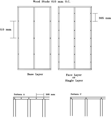
sheets of gypsum board, to ensure they were staggered as required. Diagrams showing screw
patterns for each case are given in the next section.
Not illustrated are the layouts used with resilient channels. In all cases having resilient channels
the attachment points are only into the resilient channels. Along the edges of the sheets on all
layers the screws are placed 305 mm apart. Within the field (central area away from the edges)
the screws are spaced at 610 mm for the base layer and at 305 mm for single and face layers.
To minimize installation variability, standard type “S” gypsum board screws were used in all
cases, and were installed (using an electric screw gun) so heads were just below the surface of the
gypsum board, but not breaking the surface paper.
To minimize the effect of variations due to stud changes, sets of stud assemblies were re-used.
Only nine or fewer changes of screws were used on either side of a set of studs except in cases
Council Canada
Page 9
where gypsum board was attached to resilient channels which could easily be replaced,. The
screw positions were shifted (by about 1 cm) from one case to the next to avoid previous screw
holes.
The effect of some possible variants from standard installation were examined for specimens
with 25 gauge (0.50 mm) steel framing. For fire resistance, the 1990 National Building Code
requires that non-loadbearing (25-gauge or 26-gauge) steel studs not be screwed to the upper
track; that is, installation should conform to pattern (b) in Figures 1 and 6. Included in the study
for the purpose of comparison are specimens with screw patterns (a) to (d).
Omitting screws at the upper edge of the gypsum board is also recommended for simple wood
stud and staggered wood stud walls where potential uplift by roof trusses is of concern.
Finishing at Joints and Edges
: In normal construction practice, joints and edges of gypsum
board walls are finished with joint compound and tape. However, repeated sound transmission
testing of several wall specimens while the joint compound was drying confirmed that walls
finished in this manner require about two days curing before achieving stable sound transmission
performance. Since a series of over 200 walls was planned, a more rapid joint finishing
technique was clearly desirable. Comparisons for four trial specimens showed that caulking
joints and covering them with aluminum tape gave sound transmission performance at all
frequencies within a fraction of a decibel of that for standard finish with joint compound after
curing; the STC was the same in all cases. If the joints were simply taped, the STC values tended
to be 1 lower. If joints were filled with a mastic compound (used by some acoustical testing
laboratories to fill joints), high frequency sound transmission loss and STC values tended to be
higher than those for the standard finish. Hence, the caulking and tape finish were used to seal
joints for all specimens reported here.
Council Canada
Page 10
GYPSUM BOARD ATTACHMENT DETAILS
This section illustrates the screw attachment layouts used.
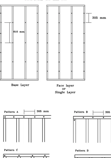
Screw attachment to non-loadbearing steel studs at 600 mm o.c:
Figure 3:
Screw attachment layout for single or double-ply gypsum board attached parallel
to non-loadbearing steel studs at 600 mm o.c., single tracks at top and bottom.
Top and bottom track attachment patterns:
Pattern B
is required for the top track of single, face and base layers for fire resistance
(Clause 18.2.6 of CAN/CSA-A82.31-M91 and National Building Code of Canada 1990,
Section 9.24.3.2) and studs are not attached to top track
Pattern A
for the bottom track of single, face, and base layers.
Patterns A and B
meet the requirements of CAN/CSA-A82.31-M91, Clause 12.2.3.1, and
National Building Code of Canada 1990, Section 9.29.5.9.
Council Canada
Page 11
Pattern C and D
were used for the top track in some cases as discussed in the text.
Screw attachment to wood studs at 600 mm o.c:
Figure 4:
Screw attachment layout for single or double-ply gypsum board attached parallel
to wood studs at 600 mm o.c., single plates at top and bottom.
Top and bottom plate attachment patterns:
Pattern A
for single or face layer
Pattern C
for base layer
Meets requirements of CAN/CSA-A82.31-M91, Clause 7.3.4, and National Building Code of
Canada 1990, Section 9.29.5.9.
Council Canada
Page 12
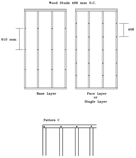
Screw attachment to wood studs at 400 mm o.c:
Figure 5:
Screw attachments layout for single or double-ply gypsum board attached
parallel to wood studs at 400 mm o.c., double plate at top, single plate at bottom.
Top and bottom plate attachment patterns:
Pattern C
for single, face and base layers
Meets requirements of CAN/CSA-A82.31-M91, Clause 7.3.4, and National Building Code of
Canada 1990, Section 9.29.5.9.
Council Canada
Page 13
Screw attachment to steel studs at 400 mm o.c.:
Figure 6:
Screw attachment layout for single and double-ply gypsum board attached
parallel to steel studs at 400 mm o.c., single tracks at top and bottom
Top and bottom track attachment patterns:
For non-loadbearing steel studs,
Pattern B
is required for the top track of single, face and base layers for fire resistance
(Clause 18.2.6 of CAN/CSA-A82.31-M91 and National Building Code of Canada 1990,
Section 9.24.3.2) and studs are not attached to top track
Pattern A
for bottom track of single, face, and base layers.
Patterns A and B
meet requirements of CAN/CSA-A82.31-M91, Clause 12.2.3.1, and National
Building Code of Canada 1990, Section 9.29.5.9.
Council Canada
Page 14
For loadbearing studs:
Pattern A
for the top and bottom track, however since the screw spacing is 300 mm,
there will only be a screw into the stud at the joint between sheets of gypsum board.
Meets requirements of CAN/CSA-A82.31-M91, Clause 12.2.3.1, and National Building Code of
Canada 1990, Section 9.29.5.9.
CHARACTERISTICS OF MATERIALS
Properties of the materials were characterized as fully as possible. The specific properties
measured and/or recorded included:
•
Dimensions and weight for every component (framing, insulation, gypsum board, etc.) of
each wall specimen, together with any special features of the materials or installation.
•
Moisture content for each wood stud. This was measured at FORINTEK, and
subsequently checked at IRC/NRCC laboratory during the testing with each wood frame
assembly. Wood studs were conditioned in the FORINTEK laboratories at 50% relative
humidity, to establish consistent moisture content. The water content was intended to be
representative of that for wall assemblies several years after construction.
•
Airflow resistivity for samples of each type of absorptive material. This was measured at
IRC/NRCC in accordance with ASTM method C522-87.
Most of the materials used in these assemblies are manufactured products with clearly defined
dimensions and other properties. The exception to this rule is cellulose fibre, for which the base
material has controlled properties, but the installation permits some variation, as it is blown or
sprayed into the wall cavities on site. This permits variation in density, which affects air flow
resistance, total weight, and stiffness of the resulting cavity fill. The density was measured when
each wall specimen with cellulose fiber was taken apart, and is presented in the tables.
Council Canada
Page 15
ABSORPTIVE MATERIAL
The weight of absorptive material was recorded for each specimen tested. These values were
used to calculate the average weight per unit area, and the density. For wet-sprayed cellulose
fibre, the actual thickness was sampled at many positions to determine the average. For blown-in
cellulose fibre, the thickness was taken to be the depth of the stud cavity.
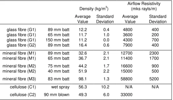
Airflow resistance was measured in accordance with ASTM C522-87 for samples of each type of
absorptive material (square samples 150 x 150 mm). For airflow measurement of loose fill
cellulose fibre material, the material was compressed in the specimen holder to approximately
the same density obtained when it was blown into the wall cavities. Several tests with different
compression showed the airflow resistivity was quite sensitive to compression for this material.
Values should therefore be recognized as rather uncertain; significant changes might occur for
the range of densities observed in wall specimens. Data are listed in Table 2.
Table 2: Density and airflow resistivity for samples of absorptive material.
Density (kg/m
3
)
Airflow Resistivity
(mks rayls/m)
Average
Value
Standard
Deviation
Average
Value
Standard
Deviation
glass fibre (G1)
89 mm batt
12.2
0.4
4800
400
glass fibre (G1)
65 mm batt
11.7
1.0
3600
200
glass fibre (G1)
150 mm batt
11.2
0.0
4300
700
glass fibre (G2)
89 mm batt
16.4
0.6
7900
400
mineral fibre (M1)
89 mm batt
32.6
2.1
12700
2300
mineral fibre (M1)
65 mm batt
36.7
2.1
11400
1700
mineral fibre (M2)
75 mm batt
44.2
1.7
16600
900
mineral fibre (M2)
40 mm batt
51.9
2.2
15000
500
mineral fibre (M3)
83 mm batt
98.1
1.3
58800
5200
cellulose (C1)
wet spray
56.3
10.2
N/A
N/A
cellulose (C2)
90 mm blown
49.3
6.0
33000
Council Canada
Page 16
WOOD STUDS
The weight of the wood studs was recorded for each wall specimen. The average weight per
metre of the nominal 38x89 mm studs was 1.36 kg/m with a standard deviation of 0.06 kg/m.
The average moisture content was determined by FORINTEK to be 9.4% with a standard
deviation of 0.5%. The moisture content was also monitored periodically over the time each
specimen was in place in the acoustics test chambers; variations were less than 1% moisture
content in all cases.
STEEL FRAMING
Weights and dimensions were recorded for all studs and/or resilient furring channels in each wall
specimen. The weight per metre for each type varied only slightly, as shown by the statistics in
Table 3.
Table B3: Dimensions and weight of steel framing.
Weight per Unit Length
(kg/m)
Nominal Type
Average
Value
Standard
Deviation
Measured
Cross Section
(mm x mm)
31x92 mm 25 gauge (0.53 mm) steel studs
0.55
0.03
30 x 91
31x92 mm 25 gauge (0.53 mm) steel stud track
0.59
0.06
30 x 91
31x64 mm 25 gauge (0.53 mm) steel studs
0.47
0.01
32 x 65
31x64 mm 25 gauge (0.53 mm) steel stud track
0.42
0.01
32 x 65
31x152 mm 25 gauge (0.53 mm) steel studs
0.78
0.01
30 x 150
31x152 mm 25 gauge (0.53 mm) steel stud track
0.94
0.01
30 x 150
31x41 mm 25 gauge (0.53 mm) steel studs
0.39
0.01
32 x 40
31x41 mm 25 gauge (0.53 mm) steel stud track
0.36
0.04
32 x 40
31x152 mm 18 gauge (1.22 mm) steel studs
2.41
0.01
40 x 150
31x152 mm 18 gauge (1.22 mm) steel stud track
1.97
0.01
30 x 150
31x92 mm 18 gauge (1.22 mm) steel studs
1.79
0.04
40 x 91
31x92 mm 18 gauge (1.22 mm) steel stud track
1.48
0.01
30 x 91
31x92 mm 16 gauge (1.52 mm) steel studs
2.24
0.01
40 x 91
31x92 mm 16 gauge (1.52 mm) steel stud track
1.89
0.01
30 x 91
13 mm 26 gauge (0.45 mm) galvanized steel
resilient channel
Council Canada
Page 17
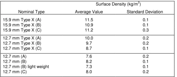
GYPSUM BOARD
The weight of each sheet of gypsum board was recorded. The weights and the total wall area
were used to calculate the surface densities given in Table 4. The variability in these values was
small.
Table 4: Surface density for each gypsum board type.
Surface Density (kg/m
2
)
Nominal Type
Average Value
Standard Deviation
15.9 mm Type X (A)
11.5
0.1
15.9 mm Type X (B)
10.9
0.1
15.9 mm Type X (C)
11.2
0.3
12.7 mm Type X (A)
10.0
0.2
12.7 mm Type X (B)
9.7
0.2
12.7 mm Type X (C)
8.7
0.1
12.7 mm (A)
7.6
0.2
12.7 mm (B)
8.2
0.1
12.7 mm (B) light weight
7.3
0.1
12.7 mm (C)
8.0
0.2
All gypsum board sheets were initially conditioned horizontally on flat pallets. When required,
sheets were placed in the conditioning laboratory in piles with 3 mm veneer spacers between
each sheet to expose all surfaces to the conditioned atmosphere. The gypsum board was held in
this way for at least two months even though steady state conditions were attained in a much
shorter period of time. The weight of select panels was measured on a daily basis to determine
the rate of conditioning. The gypsum board was conditioned using the same environmental
conditions (50% relative humidity and 20
°
C) that were used for the wood studs. The moisture
content of the face paper reached 10% relatively quickly. The moisture content of the gypsum
(as measured with the same moisture meter which is not calibrated for gypsum board) was found
to be approximately 4-5 % higher than for wood under the same environmental conditions.
Equilibrium was attained fairly quickly.
Council Canada
Page 18
INDIVIDUAL SPECIMEN DATA
This section provides the detailed results for each specimen tested, with one page summarizing
the results of each test.
Note that all dimensions are rounded to the nearest millimetre. Thus 12.7 mm gypsum board is
listed as 13 mm.
The material codes used in the tables of material properties are the same as used in Tables 2 and
4.
The code given at the top right of each page gives a provides a shorthand description of the wall
construction. The abbreviations used are:
nGxx
‘n’ layers of Gypsum board with a nominal thickness of ‘xx’ mm.
WFBxx
Wood fibre board with a nominal thickness of ‘xx’ mm.
WSxx(ss)
Wood studs with a nominal depth of ‘xx’ mm spaced ‘ss’ mm apart.
SWSxx(ss)
Staggered wood studs with a nominal depth of ‘xx’ mm spaced ‘ss’ mm apart.
SSxx(ss)
Steel studs with a nominal depth of ‘xx’ mm spaced ‘ss’ mm apart.
RCxx(ss)
Resilient channels with a thickness of ‘xx’ mm and spaced ‘ss’ mm apart.
GFBxx
Glass fibre batts with a nominal thickness of ‘xx’ mm.
MFBxx
Mineral fibre batts with a nominal thickness of ‘xx’ mm.
CFLxx
Blown cellulose fibre with a nominal thickness of ‘xx’ mm.
CFSxx
Sprayed cellulose fibre with a nominal thickness of ‘xx’ mm.
AIRxx
Air space with a nominal depth of ‘xx’ mm.
Council Canada
G13_WS90(406)_CFL90_G13
Element
Description:
1
single layer of 13 mm type X gypsum board2
90 mm wood studs at 406 mm on centre3
90 mm of blown cellulose fibre insulation in cavity4
single layer of 13 mm type X gypsum boardTestID
TL-93-176
element 1
element 2
element 3
element 4
STC
3250 Hz
21.5 gypsum board stud insulation gypsum board63 Hz
19.5 AX wood C2 AX80 Hz
21.8 13 90 90 13100 Hz
16.3125 Hz
12.5 406160 Hz
11.4 10.0 4.8 10.1200 Hz
22.6 1.4250 Hz
32.7 74.4 41.3 32.7 74.9315 Hz
36.7 406 406400 Hz
42.0 406 406500 Hz
44.2 c c630 Hz
48.4 c c800 Hz
53.4 yes1000 Hz
56.1 yes1250 Hz
57.3 vertical vertical1600 Hz
57.42000 Hz
55.42500 Hz
45.53150 Hz
43.04000 Hz
47.45000 Hz
53.06300 Hz
57.4 16 19 22 25 28 31 32 33 34 35 36 36 36 36 36 36fastener base track pattern stud attached to top track double header
orientation total weight kg fastener spacing - edge mm fastener spacing - field mm fastener top track pattern gauge spacing mm surface density kg/m2 linear density kg/m
TL-93-176
type material thickness mmTL-93-176
STC 32
0
10
20
30
40
50
60
70
80
90
100
63
125
250
500
1k
2k
4k
Frequency
Tr
ansmission loss, dB
wall_1
3/13/02
Council Canada
G13_WS90(406)_MFB90_G13
Element
Description:
1
single layer of 13 mm gypsum board2
90 mm wood studs at 406 mm on centre3
90 mm of mineral fibre insulation in cavity4
single layer of 13 mm gypsum boardTestID
TL-93-166
element 1
element 2
element 3
element 4
STC
3350 Hz
20.1 gypsum board stud insulation gypsum board63 Hz
16.7 B wood M1 B80 Hz
20.5 13 90 90 13100 Hz
14.1125 Hz
8.6 406160 Hz
16.4 8.3 2.3 8.3200 Hz
30.5 1.6250 Hz
33.9 61.5 46.8 17.3 61.8315 Hz
36.0 406 406400 Hz
43.4 406 406500 Hz
43.8 c c630 Hz
44.2 c c800 Hz
49.4 yes1000 Hz
51.1 yes1250 Hz
53.0 vertical vertical1600 Hz
53.92000 Hz
53.12500 Hz
44.83150 Hz
40.44000 Hz
43.45000 Hz
49.26300 Hz
54.1 17 20 23 26 29 32 33 34 35 36 37 37 37 37 37 37fastener base track pattern stud attached to top track double header
orientation total weight kg fastener spacing - edge mm fastener spacing - field mm fastener top track pattern gauge spacing mm surface density kg/m2 linear density kg/m
TL-93-166
type material thickness mmTL-93-166
STC 33
0
10
20
30
40
50
60
70
80
90
100
63
125
250
500
1k
2k
4k
Frequency
Tr
ansmission loss, dB
wall_2
3/13/02
Council Canada
G13_WS90(406)_MFB90_G13
Element
Description:
1
single layer of 13 mm type X gypsum board2
90 mm wood studs at 406 mm on centre3
90 mm of mineral fibre insulation in cavity4
single layer of 13 mm type X gypsum boardTestID
TL-93-188
element 1
element 2
element 3
element 4
STC
3450 Hz
21.2 gypsum board stud insulation gypsum board63 Hz
16.9 AX wood M1 AX80 Hz
20.9 13 90 90 13100 Hz
14.9125 Hz
9.8 406160 Hz
17.9 10.1 2.4 10.1200 Hz
32.4 1.4250 Hz
35.9 75.1 41.3 17.8 75.4315 Hz
35.6 406 406400 Hz
42.7 406 406500 Hz
44.1 c c630 Hz
44.1 c c800 Hz
49.1 yes1000 Hz
51.1 yes1250 Hz
53.5 vertical vertical1600 Hz
54.42000 Hz
52.32500 Hz
42.33150 Hz
40.44000 Hz
44.75000 Hz
50.86300 Hz
55.3 18 21 24 27 30 33 34 35 36 37 38 38 38 38 38 38fastener base track pattern stud attached to top track double header
orientation total weight kg fastener spacing - edge mm fastener spacing - field mm fastener top track pattern gauge spacing mm surface density kg/m2 linear density kg/m
TL-93-188
type material thickness mmTL-93-188
STC 34
0
10
20
30
40
50
60
70
80
90
100
63
125
250
500
1k
2k
4k
Frequency
Tr
ansmission loss, dB
wall_3
3/13/02
Council Canada
G16_WS90(406)_MFB90_G16
Element
Description:
1
single layer of 16 mm type X gypsum board2
90 mm wood studs at 406 mm on centre3
90 mm of mineral fibre insulation in cavity4
single layer of 16 mm type X gypsum boardTestID
TL-93-157
element 1
element 2
element 3
element 4
STC
3450 Hz
22.3 gypsum board stud insulation gypsum board63 Hz
18.5 CX wood M1 CX80 Hz
23.2 16 90 90 16100 Hz
18.1125 Hz
13.0 406160 Hz
12.7 11.0 2.3 11.0200 Hz
25.0 1.6250 Hz
37.9 81.7 46.8 17.3 81.4315 Hz
35.8 406 406400 Hz
36.1 406 406500 Hz
39.4 c c630 Hz
44.2 c c800 Hz
43.2 yes1000 Hz
46.7 yes1250 Hz
47.4 vertical vertical1600 Hz
46.82000 Hz
40.22500 Hz
37.43150 Hz
42.54000 Hz
47.85000 Hz
52.96300 Hz
57.2 18 21 24 27 30 33 34 35 36 37 38 38 38 38 38 38fastener base track pattern stud attached to top track double header
orientation total weight kg fastener spacing - edge mm fastener spacing - field mm fastener top track pattern gauge spacing mm surface density kg/m2 linear density kg/m
TL-93-157
type material thickness mmTL-93-157
STC 34
0
10
20
30
40
50
60
70
80
90
100
63
125
250
500
1k
2k
4k
Frequency
Tr
ansmission loss, dB
wall_4
3/13/02
Council Canada
G13_WS90(406)_CFL90_2G13
Element
Description:
1
single layer of 13 mm type X gypsum board2
90 mm wood studs at 406 mm on centre3
90 mm of blown cellulose fibre insulation in cavity4
single layer of 13 mm type X gypsum board5
single layer of 13 mm type X gypsum boardTestID
TL-93-175
element 1
element 2
element 3
element 4
element 5
STC
3750 Hz
23.6 gypsum board stud insulation gypsum board gypsum board63 Hz
21.1 AX wood C2 AX AX80 Hz
23.7 13 90 90 13 13100 Hz
18.2125 Hz
13.4 406160 Hz
16.3 10.0 4.8 10.1 10.0200 Hz
28.4 1.4250 Hz
37.3 74.4 41.3 32.7 74.9 74.5315 Hz
41.4 406 610 406400 Hz
46.7 406 610 406500 Hz
47.5 c c c630 Hz
50.1 c c c800 Hz
54.0 yes1000 Hz
56.9 yes1250 Hz
58.7 vertical vertical vertical1600 Hz
59.22000 Hz
57.32500 Hz
47.33150 Hz
45.84000 Hz
50.45000 Hz
56.76300 Hz
61.2 21 24 27 30 33 36 37 38 39 40 41 41 41 41 41 41fastener base track pattern stud attached to top track double header
orientation total weight kg fastener spacing - edge mm fastener spacing - field mm fastener top track pattern gauge spacing mm surface density kg/m2 linear density kg/m
TL-93-175
type material thickness mmTL-93-175
STC 37
0
10
20
30
40
50
60
70
80
90
100
63
125
250
500
1k
2k
4k
Frequency
Tr
ansmission loss, dB
wall_5
3/13/02
Council Canada
G13_WS90(406)_MFB90_2G13
Element
Description:
1
single layer of 13 mm gypsum board2
90 mm wood studs at 406 mm on centre3
90 mm of mineral fibre insulation in cavity4
single layer of 13 mm gypsum board5
single layer of 13 mm gypsum boardTestID
TL-93-167
element 1
element 2
element 3
element 4
element 5
STC
3550 Hz
21.8 gypsum board stud insulation gypsum board gypsum board63 Hz
19.0 B wood M1 B B80 Hz
23.2 13 90 90 13 13100 Hz
16.2125 Hz
11.5 406160 Hz
19.5 8.3 2.3 8.3 8.3200 Hz
33.6 1.6250 Hz
37.1 61.5 46.8 17.3 61.8 61.7315 Hz
38.0 406 610 406400 Hz
44.7 406 610 406500 Hz
45.0 c c c630 Hz
45.1 c c c800 Hz
49.5 yes1000 Hz
50.8 yes1250 Hz
53.3 vertical vertical vertical1600 Hz
55.12000 Hz
55.22500 Hz
47.73150 Hz
43.84000 Hz
47.35000 Hz
53.06300 Hz
57.7 19 22 25 28 31 34 35 36 37 38 39 39 39 39 39 39fastener base track pattern stud attached to top track double header
orientation total weight kg fastener spacing - edge mm fastener spacing - field mm fastener top track pattern gauge spacing mm surface density kg/m2 linear density kg/m
TL-93-167
type material thickness mmTL-93-167
STC 35
0
10
20
30
40
50
60
70
80
90
100
63
125
250
500
1k
2k
4k
Frequency
Tr
ansmission loss, dB
wall_6
3/13/02
Council Canada
G16_WS90(406)_MFB90_2G16
Element
Description:
1
single layer of 16 mm type X gypsum board2
90 mm wood studs at 406 mm on centre3
90 mm of mineral fibre insulation in cavity4
single layer of 16 mm type X gypsum board5
single layer of 16 mm type X gypsum boardTestID
TL-93-158
element 1
element 2
element 3
element 4
element 5
STC
3650 Hz
24.4 gypsum board stud insulation gypsum board gypsum board63 Hz
21.9 CX wood M1 CX CX80 Hz
25.5 16 90 90 16 16100 Hz
21.3125 Hz
16.3 406160 Hz
15.0 11.0 2.3 11.0 11.0200 Hz
25.5 1.6250 Hz
40.5 81.7 46.8 17.3 81.4 81.7315 Hz
38.6 406 610 406400 Hz
37.5 406 610 406500 Hz
41.4 c c c630 Hz
45.9 c c c800 Hz
45.4 yes1000 Hz
48.4 yes1250 Hz
49.4 vertical vertical vertical1600 Hz
49.22000 Hz
43.32500 Hz
41.33150 Hz
46.64000 Hz
51.75000 Hz
56.96300 Hz
61.2 20 23 26 29 32 35 36 37 38 39 40 40 40 40 40 40fastener base track pattern stud attached to top track double header
orientation total weight kg fastener spacing - edge mm fastener spacing - field mm fastener top track pattern gauge spacing mm surface density kg/m2 linear density kg/m
TL-93-158
type material thickness mmTL-93-158
STC 36
0
10
20
30
40
50
60
70
80
90
100
63
125
250
500
1k
2k
4k
Frequency
Tr
ansmission loss, dB
wall_7
3/13/02
Council Canada
2G13_WS90(406)_CFL90_2G13
Element
Description:
1
single layer of 13 mm type X gypsum board2
single layer of 13 mm type X gypsum board3
90 mm wood studs at 406 mm on centre4
90 mm of blown cellulose fibre insulation in cavity5
single layer of 13 mm type X gypsum board6
single layer of 13 mm type X gypsum boardTestID
TL-93-174
element 1
element 2
element 3
element 4
element 5
element 6
STC
3850 Hz
26.8 gypsum board gypsum board stud insulation gypsum board gypsum board63 Hz
23.1 AX AX wood C2 AX AX80 Hz
26.2 13 13 90 90 13 13100 Hz
20.9125 Hz
15.4 406160 Hz
17.0 10.0 10.0 4.8 10.1 10.0200 Hz
30.1 1.4250 Hz
41.0 74.2 74.4 41.3 32.7 74.9 74.5315 Hz
41.4 406 610 610 406400 Hz
47.6 406 610 610 406500 Hz
48.1 c c c c630 Hz
50.0 c c c c800 Hz
53.9 yes1000 Hz
56.0 yes1250 Hz
58.1 vertical vertical vertical vertical1600 Hz
60.12000 Hz
57.92500 Hz
48.63150 Hz
48.64000 Hz
53.55000 Hz
59.66300 Hz
64.3 22 25 28 31 34 37 38 39 40 41 42 42 42 42 42 42fastener base track pattern stud attached to top track double header
orientation total weight kg fastener spacing - edge mm fastener spacing - field mm fastener top track pattern gauge spacing mm surface density kg/m2 linear density kg/m
TL-93-174
type material thickness mmTL-93-174
STC 38
0
10
20
30
40
50
60
70
80
90
100
63
125
250
500
1k
2k
4k
Frequency
Tr
ansmission loss, dB
wall_8
3/13/02
Council Canada
G13_SS150(610)_GFB150_G13
Element
Description:
1
single layer of 13 mm type X gypsum board2
150 mm steel studs at 610 mm on centre3
150 mm of glass fibre insulation in cavity4
single layer of 13 mm type X gypsum boardTestID
TL-93-299
element 1
element 2
element 3
element 4
STC
5250 Hz
12.3 gypsum board stud insulation gypsum board63 Hz
12.4 AX steel G1 AX80 Hz
20.6 13 150 150 13100 Hz
24.8 25125 Hz
30.1 610160 Hz
35.1 10.2 1.7 10.1200 Hz
40.3 0.8250 Hz
46.6 75.8 17.2 12.5 74.8315 Hz
51.2 305 305400 Hz
56.6 305 305500 Hz
61.4 a a630 Hz
63.5 a a800 Hz
65.1 yes1000 Hz
67.41250 Hz
68.1 vertical vertical1600 Hz
68.92000 Hz
64.52500 Hz
52.13150 Hz
47.54000 Hz
50.35000 Hz
54.56300 Hz
57.0 36 39 42 45 48 51 52 53 54 55 56 56 56 56 56 56fastener base track pattern stud attached to top track double header
orientation total weight kg fastener spacing - edge mm fastener spacing - field mm fastener top track pattern gauge spacing mm surface density kg/m2 linear density kg/m
TL-93-299
type material thickness mmTL-93-299
STC 52
0
10
20
30
40
50
60
70
80
90
100
63
125
250
500
1k
2k
4k
Frequency
Tr
ansmission loss, dB
wall_9
3/13/02
Council Canada
G13_SS65(406)_MFB65_G13
Element
Description:
1
single layer of 13 mm type X gypsum board2
65 mm steel studs at 406 mm on centre3
65 mm of mineral fibre insulation in cavity4
single layer of 13 mm type X gypsum boardTestID
TL-93-064
element 1
element 2
element 3
element 4
STC
3650 Hz
20.2 gypsum board stud insulation gypsum board63 Hz
14.5 AX steel M1 AX80 Hz
16.5 13 65 65 13100 Hz
10.1 25125 Hz
11.7 406160 Hz
22.4 10.0 2.3 9.9200 Hz
32.5 0.5250 Hz
41.3 74.1 13.0 17.4 73.7315 Hz
46.0 305 305400 Hz
50.6 305 305500 Hz
55.1 c c630 Hz
60.0 c c800 Hz
62.6 yes1000 Hz
63.91250 Hz
64.0 vertical vertical1600 Hz
64.92000 Hz
60.92500 Hz
47.43150 Hz
45.14000 Hz
48.55000 Hz
53.26300 Hz
55.5 20 23 26 29 32 35 36 37 38 39 40 40 40 40 40 40fastener base track pattern stud attached to top track double header
orientation total weight kg fastener spacing - edge mm fastener spacing - field mm fastener top track pattern gauge spacing mm surface density kg/m2 linear density kg/m
TL-93-064
type material thickness mmTL-93-064
STC 36
0
10
20
30
40
50
60
70
80
90
100
63
125
250
500
1k
2k
4k
Frequency
Tr
ansmission loss, dB
wall_10
3/13/02
Council Canada
G13_SS65(406)_MFB65_G13
Element
Description:
1
single layer of 13 mm type X gypsum board2
65 mm steel studs at 406 mm on centre3
65 mm of mineral fibre insulation in cavity4
single layer of 13 mm type X gypsum boardTestID
TL-93-067
element 1
element 2
element 3
element 4
STC
3550 Hz
19.6 gypsum board stud insulation gypsum board63 Hz
15.0 AX steel M2 AX80 Hz
17.8 13 65 65 13100 Hz
10.8 25125 Hz
10.9 406160 Hz
22.4 10.1 2.9 9.9200 Hz
31.8 0.5250 Hz
42.2 74.7 13.0 21.6 73.7315 Hz
47.1 305 305400 Hz
49.9 305 305500 Hz
54.1 c c630 Hz
61.4 c c800 Hz
63.6 yes1000 Hz
66.21250 Hz
66.3 vertical vertical1600 Hz
67.42000 Hz
62.52500 Hz
48.63150 Hz
47.54000 Hz
50.95000 Hz
56.06300 Hz
57.6 19 22 25 28 31 34 35 36 37 38 39 39 39 39 39 39fastener base track pattern stud attached to top track double header
orientation total weight kg fastener spacing - edge mm fastener spacing - field mm fastener top track pattern gauge spacing mm surface density kg/m2 linear density kg/m
TL-93-067
type material thickness mmTL-93-067
STC 35
0
10
20
30
40
50
60
70
80
90
100
63
125
250
500
1k
2k
4k
Frequency
Tr
ansmission loss, dB
wall_11
3/13/02
Council Canada
G13_SS65(406)_MFB65_G13
Element
Description:
1
single layer of 13 mm gypsum board2
65 mm steel studs at 406 mm on centre3
65 mm of mineral fibre insulation in cavity4
single layer of 13 mm gypsum boardTestID
TL-93-069
element 1
element 2
element 3
element 4
STC
3350 Hz
18.1 gypsum board stud insulation gypsum board63 Hz
14.3 B steel M1 B80 Hz
16.6 13 65 65 13100 Hz
11.3 25125 Hz
9.4 406160 Hz
19.3 8.2 2.3 8.3200 Hz
29.1 0.5250 Hz
36.7 60.8 13.0 17.4 61.4315 Hz
42.4 305 305400 Hz
48.1 305 305500 Hz
53.1 d d630 Hz
57.2 d d800 Hz
61.3 yes1000 Hz
63.11250 Hz
64.6 vertical vertical1600 Hz
65.12000 Hz
62.62500 Hz
51.03150 Hz
45.34000 Hz
47.95000 Hz
53.36300 Hz
56.1 17 20 23 26 29 32 33 34 35 36 37 37 37 37 37 37fastener base track pattern stud attached to top track double header
orientation total weight kg fastener spacing - edge mm fastener spacing - field mm fastener top track pattern gauge spacing mm surface density kg/m2 linear density kg/m
TL-93-069
type material thickness mmTL-93-069
STC 33
0
10
20
30
40
50
60
70
80
90
100
63
125
250
500
1k
2k
4k
Frequency
Tr
ansmission loss, dB
wall_12
3/13/02
Council Canada
G13_SS65(406)_MFB65_G13
Element
Description:
1
single layer of 13 mm gypsum board2
65 mm steel studs at 406 mm on centre3
65 mm of mineral fibre insulation in cavity4
single layer of 13 mm gypsum boardTestID
TL-93-070
element 1
element 2
element 3
element 4
STC
3450 Hz
19.3 gypsum board stud insulation gypsum board63 Hz
14.3 B steel M1 B80 Hz
16.7 13 65 65 13100 Hz
11.5 25125 Hz
9.7 406160 Hz
19.1 8.2 2.3 8.3200 Hz
29.3 0.5250 Hz
36.9 60.8 13.0 17.4 61.4315 Hz
41.9 305 305400 Hz
47.5 305 305500 Hz
52.7 c c630 Hz
57.2 c c800 Hz
61.5 yes1000 Hz
63.21250 Hz
64.5 vertical vertical1600 Hz
65.12000 Hz
63.12500 Hz
50.63150 Hz
45.24000 Hz
48.05000 Hz
53.56300 Hz
56.3 18 21 24 27 30 33 34 35 36 37 38 38 38 38 38 38fastener base track pattern stud attached to top track double header
orientation total weight kg fastener spacing - edge mm fastener spacing - field mm fastener top track pattern gauge spacing mm surface density kg/m2 linear density kg/m
TL-93-070
type material thickness mmTL-93-070
STC 34
0
10
20
30
40
50
60
70
80
90
100
63
125
250
500
1k
2k
4k
Frequency
Tr
ansmission loss, dB
wall_13
3/13/02
Council Canada
G13_SS65(406)_MFR57_G13
Element
Description:
1
single layer of 13 mm gypsum board2
65 mm steel studs at 406 mm on centre3
57 mm of mineral fibre insulation in cavity4
single layer of 13 mm gypsum boardTestID
TL-93-068
element 1
element 2
element 3
element 4
STC
3650 Hz
20.9 gypsum board stud insulation gypsum board63 Hz
16.2 B steel M3 B80 Hz
18.0 13 65 57 13100 Hz
13.4 25125 Hz
12.1 406160 Hz
21.1 8.2 5.3 8.3200 Hz
30.4 0.5250 Hz
35.6 60.8 13.0 39.4 61.4315 Hz
40.8 305 305400 Hz
47.9 305 305500 Hz
52.4 c c630 Hz
57.7 c c800 Hz
63.2 yes1000 Hz
66.01250 Hz
67.3 vertical vertical1600 Hz
68.62000 Hz
64.32500 Hz
50.83150 Hz
50.04000 Hz
53.25000 Hz
57.56300 Hz
59.1 20 23 26 29 32 35 36 37 38 39 40 40 40 40 40 40fastener base track pattern stud attached to top track double header
orientation total weight kg fastener spacing - edge mm fastener spacing - field mm fastener top track pattern gauge spacing mm surface density kg/m2 linear density kg/m
TL-93-068
type material thickness mmTL-93-068
STC 36
0
10
20
30
40
50
60
70
80
90
100
63
125
250
500
1k
2k
4k
Frequency
Tr
ansmission loss, dB
wall_14
3/13/02
Council Canada
G13_SS65(610)_GFB65_G13
Element
Description:
1
single layer of 13 mm type X gypsum board2
65 mm steel studs at 610 mm on centre3
65 mm of glass fibre insulation in cavity4
single layer of 13 mm type X gypsum boardTestID
TL-93-038
element 1
element 2
element 3
element 4
STC
4550 Hz
18.2 gypsum board stud insulation gypsum board63 Hz
13.9 AX steel G1 AX80 Hz
15.0 13 65 65 13100 Hz
14.0 25125 Hz
21.3 610160 Hz
27.7 10.0 0.8 10.1200 Hz
32.4 0.5250 Hz
39.1 74.3 9.8 5.9 75.2315 Hz
44.0 305 305400 Hz
50.6 305 305500 Hz
54.3 c c630 Hz
57.0 c c800 Hz
60.1 yes1000 Hz
62.11250 Hz
62.8 vertical vertical1600 Hz
63.32000 Hz
59.42500 Hz
47.03150 Hz
44.14000 Hz
48.15000 Hz
53.06300 Hz
55.5 29 32 35 38 41 44 45 46 47 48 49 49 49 49 49 49fastener base track pattern stud attached to top track double header
orientation total weight kg fastener spacing - edge mm fastener spacing - field mm fastener top track pattern gauge spacing mm surface density kg/m2 linear density kg/m
TL-93-038
type material thickness mmTL-93-038
STC 45
0
10
20
30
40
50
60
70
80
90
100
63
125
250
500
1k
2k
4k
Frequency
Tr
ansmission loss, dB
wall_15
3/13/02
Council Canada
G13_SS65(610)_GFB65_G13
Element
Description:
1
single layer of 13 mm gypsum board2
65 mm steel studs at 610 mm on centre3
65 mm of glass fibre insulation in cavity4
single layer of 13 mm gypsum boardTestID
TL-93-041
element 1
element 2
element 3
element 4
STC
4250 Hz
17.6 gypsum board stud insulation gypsum board63 Hz
13.1 B steel G1 B80 Hz
14.4 13 65 65 13100 Hz
11.9 25125 Hz
17.8 610160 Hz
24.6 8.3 0.8 8.3200 Hz
29.1 0.5250 Hz
35.3 61.7 9.9 5.9 61.3315 Hz
41.5 305 305400 Hz
47.5 305 305500 Hz
50.0 d d630 Hz
53.3 d d800 Hz
56.01000 Hz
59.11250 Hz
61.7 vertical vertical1600 Hz
62.92000 Hz
63.42500 Hz
51.53150 Hz
44.34000 Hz
46.75000 Hz
50.86300 Hz
54.2 26 29 32 35 38 41 42 43 44 45 46 46 46 46 46 46fastener base track pattern stud attached to top track double header
orientation total weight kg fastener spacing - edge mm fastener spacing - field mm fastener top track pattern gauge spacing mm surface density kg/m2 linear density kg/m
TL-93-041
type material thickness mmTL-93-041
STC 42
0
10
20
30
40
50
60
70
80
90
100
63
125
250
500
1k
2k
4k
Frequency
Tr
ansmission loss, dB
wall_16
3/13/02
Council Canada
G13_SS65(610)_GFB65_G13
Element
Description:
1
single layer of 13 mm gypsum board2
65 mm steel studs at 610 mm on centre3
65 mm of glass fibre insulation in cavity4
single layer of 13 mm gypsum boardTestID
TL-93-043
element 1
element 2
element 3
element 4
STC
4350 Hz
17.3 gypsum board stud insulation gypsum board63 Hz
13.3 B steel G1 B80 Hz
14.7 13 65 65 13100 Hz
12.3 25125 Hz
18.7 610160 Hz
24.9 8.3 0.8 8.3200 Hz
29.1 0.5250 Hz
35.3 61.7 9.9 5.9 61.3315 Hz
41.0 305 305400 Hz
47.5 305 305500 Hz
50.2 c c630 Hz
53.9 c c800 Hz
56.9 yes1000 Hz
59.61250 Hz
61.3 vertical vertical1600 Hz
63.02000 Hz
63.52500 Hz
52.03150 Hz
44.84000 Hz
47.45000 Hz
52.06300 Hz
55.3 27 30 33 36 39 42 43 44 45 46 47 47 47 47 47 47fastener base track pattern stud attached to top track double header
orientation total weight kg fastener spacing - edge mm fastener spacing - field mm fastener top track pattern gauge spacing mm surface density kg/m2 linear density kg/m
TL-93-043
type material thickness mmTL-93-043
STC 43
0
10
20
30
40
50
60
70
80
90
100
63
125
250
500
1k
2k
4k
Frequency
Tr
ansmission loss, dB
wall_17
3/13/02
Council Canada
G13_SS65(610)_GFB65_G13
Element
Description:
1
single layer of 13 mm gypsum board2
65 mm steel studs at 610 mm on centre3
65 mm of glass fibre insulation in cavity4
single layer of 13 mm gypsum boardTestID
TL-93-044
element 1
element 2
element 3
element 4
STC
4350 Hz
16.9 gypsum board stud insulation gypsum board63 Hz
13.1 B steel G1 B80 Hz
14.9 13 65 65 13100 Hz
12.5 25125 Hz
18.8 610160 Hz
24.6 8.3 0.8 8.3200 Hz
29.2 0.5250 Hz
35.3 61.7 9.9 5.9 61.3315 Hz
40.9 305 305400 Hz
47.5 305 305500 Hz
50.2 a a630 Hz
54.2 a a800 Hz
57.3 yes1000 Hz
60.11250 Hz
62.4 vertical vertical1600 Hz
63.62000 Hz
63.92500 Hz
52.83150 Hz
45.04000 Hz
47.45000 Hz
52.16300 Hz
55.4 27 30 33 36 39 42 43 44 45 46 47 47 47 47 47 47fastener base track pattern stud attached to top track double header
orientation total weight kg fastener spacing - edge mm fastener spacing - field mm fastener top track pattern gauge spacing mm surface density kg/m2 linear density kg/m