READ THESE TERMS AND CONDITIONS CAREFULLY BEFORE USING THIS WEBSITE.
https://nrc-publications.canada.ca/eng/copyright
Vous avez des questions? Nous pouvons vous aider. Pour communiquer directement avec un auteur, consultez la
première page de la revue dans laquelle son article a été publié afin de trouver ses coordonnées. Si vous n’arrivez pas à les repérer, communiquez avec nous à [email protected].
Questions? Contact the NRC Publications Archive team at
[email protected]. If you wish to email the authors directly, please see the first page of the publication for their contact information.
NRC Publications Archive
Archives des publications du CNRC
This publication could be one of several versions: author’s original, accepted manuscript or the publisher’s version. / La version de cette publication peut être l’une des suivantes : la version prépublication de l’auteur, la version acceptée du manuscrit ou la version de l’éditeur.
Access and use of this website and the material on it are subject to the Terms and Conditions set forth at
A Reconfigurable Concurrent Function Block Model and its
Implementation in Real-Time Java
Xu, Y.; Brennan, R.W.; Zhang, X.; Norrie, H.
https://publications-cnrc.canada.ca/fra/droits
L’accès à ce site Web et l’utilisation de son contenu sont assujettis aux conditions présentées dans le site
LISEZ CES CONDITIONS ATTENTIVEMENT AVANT D’UTILISER CE SITE WEB.
NRC Publications Record / Notice d'Archives des publications de CNRC:
https://nrc-publications.canada.ca/eng/view/object/?id=fcf07c92-61be-4dd3-a6c1-a302dd0548ba https://publications-cnrc.canada.ca/fra/voir/objet/?id=fcf07c92-61be-4dd3-a6c1-a302dd0548ba
Council Canada Institute for Information Technology de recherches Canada Institut de technologie de l’information
A Reconfigurable Concurrent Function Block Model
and its Implementation in Real-Time Java.
*
Xu, Y., Brennan, R.W., Zhang, X. and Norrie, H.
2002
* published in: Journal of Integrated Computer-Aided Engineering, Volume 9 (2002), Pages 263-279 (In press). NRC 44949.
Copyright 2002 by
National Research Council of Canada
Permission is granted to quote short excerpts and to reproduce figures and tables from this report, provided that the source of such material is fully acknowledged.
IOS Press
A reconfigurable concurrent function block
model and its implementation in real-time
Java
Robert W. Brennan
a,∗, Xiaokun Zhang
b, Yuefei Xu
cand Douglas H. Norrie
a aDepartment of Mechanical and Manufacturing Engineering, University of Calgary, Calgary, Alberta, Canada T2N 1N4
b
Centre for Computing and Information Systems, Athabasca University, 1 University Drive, Athabasca, Alberta, Canada T9S 3A3
c
Institute for Information Technology, National Research Council of Canada, 1500 Montreal Road, Bldg. M-50, Ottawa, Ontario, Canada K1A 0R6
Abstract: This paper focuses on the important holonic manufacturing systems issue of automatic and dynamic adaptability to change at the physical machine level of control. We propose a model to support configuration and reconfiguration of real-time distributed control systems that is built upon recent models for distributed intelligent control and provide an example of its implementation on a real-time Java platform.
1. Introduction
A key goal of holonic manufacturing systems (HMS) research (and arguably, its central ideal) is to develop manufacturing systems that can automatically and dy-namically adapt to change. For example, since the HMS Consortium’s [19] inception in 1992, its goal has been “to attain in manufacturing the benefits that holonic organisation provides to living organisms and societies, e.g., stability in the face of disturbances, adaptability and flexibility in the face of change, and efficient use of available resources.” [36].
Researchers from various communities (e.g., oper-ations research, artificial intelligence, agent system, holonic systems) have been tackling the general ques-tion of developing this type of “adaptive” or “agile” manufacturing system for a number of years. Recently, it has become apparent that systems composed of au-tonomous and cooperative entities (e.g., auau-tonomous and cooperative software agents and holons) show the
∗Corresponding author.
most promise as an approach to this general problem. For example, in the area of product design, researchers have successfully applied this concept to enable teams of designers to work together over widely distributed locations to design complex products using a variety of design and analysis tools (e.g., PACT [8], ACDS [9], RAPPID [30]). Similarly, in the area of enterprise in-tegration and supply chain management, agent-based and holonic concepts have been applied to manage world-wide networks of suppliers, factories, ware-houses and distributors to ensure that the fundamen-tal manufacturing requirements of material acquisition, transformation and delivery are efficiently achieved (e.g., ISCM [16], AIMS [28], CIIMPLEX [31]). As well, the notoriously difficult problem area of manufac-turing planning and scheduling has been of particular interest to multi-agent and holonic systems researchers (e.g., AARIA [2], MASCADA [6], MetaMorph [27], YAMS [29], PROSA [37]).
Another important area of research is that of real-time distributed control: i.e., the development of ap-proaches to enable real-time distributed systems to automatically reconfigure to adapt to changes in the
manufacturing environment. For example, in conven-tional real-time industrial control systems (e.g., pro-grammable logic controllers (PLC)), reconfiguration involves a process of first editing the control software offline while the system is running, then committing the change to the running control program. When the change is committed, severe disruptions and instability can occur as a result of high coupling between elements of the control software and inconsistent real time syn-chronisation. For example, a change to an output state-ment can cause a chain of unanticipated events to occur throughout a PLC ladder logic program as a result of high coupling between various rungs in the program; a change to a proportional-integral-derivative (PID) func-tion block can result in instability when process or control values are not properly synchronised. Clearly, new software approaches are required to avoid these coupling and synchronization problems when real-time distributed control applications are initially configured and later reconfigured in response to change.
As noted previously, both agent-based and holonic approaches can be applied to achieve adaptable systems at the higher, non-real-time or soft real-time planning levels of a manufacturing enterprise. However, to date all of the work on applying these concepts to the real-time control domain has only focused on implementing agents and holons at this level and not on the central holonic issue of adaptability. For example, research has been conducted into holonic models for distributed real-time control (e.g. [14,41]), distributed real-time operating systems (e.g. [3,40]), verification techniques (e.g. [38]), and robotic cell control (e.g. [18]).
This limitation of holonic systems research becomes even more apparent when one considers the key dif-ferences between agent and holonic systems concepts. Multi-agent systems is for example, can be thought of as a general software technology; manufacturing however is fundamentally concerned with “ironware” (i.e., physical equipment and products). As a result, when these two worlds merge, it becomes useful to start thinking about a different type of agent than those that populate classic agent-based systems. In particu-lar, it becomes useful to think about “physical agents” or “holons” that possess both classical software agent capabilities as well as the capability to interface with physical equipment on the shop floor. Since the phys-ical equipment that populates a manufacturing facility is typically classified as real-time (i.e., these systems tightly link correctness with timeliness [10]), real-time distributed control (and reconfiguration of these sys-tems) is of particular relevance to holonic systems re-search.
In this paper we address this important holonic sys-tems research issue and propose a model to support con-figuration and reconcon-figuration of real-time distributed control systems that is built upon recent models for dis-tributed intelligent control. We start with a description of these existing models for real-time distributed con-trol in Section 2. Next, we discuss the drawbacks of these models with respect to the holonic goal of adapt-ability, and propose a general approach for reconfigu-ration. In Section 4, we describe our approach in de-tail then provide an example of its implementation in real-time Java in Section 5. Finally, we conclude with a discussion of the benefits of this approach as well as our current work on extending our model.
2. Background
In this section we provide a brief overview of the cur-rent models for real-time distributed control. We start with a general overview of the research in this area then focus on the IEC 61499 model for distributed indus-trial process control [21]. The authors’ reconfiguration model that is reported in the remainder of this paper is linked closely to, and can be considered as extending, the IEC 61499 model described in this section.
2.1. Distributed intelligent control
Distributed intelligent control involves matching the control model more closely with the physical system. This is particularly relevant to manufacturing control systems that are required to control widely distributed devices in an environment that is prone to disruptions. With this model, control is achieved by the emer-gent behaviour of many simple, autonomous and co-operative entities that are based on the principles of object-oriented and agent-based systems.
Although there has been a considerable amount of work on agent-based approaches to the upper/planning and scheduling level of control very little work has been done on applying these techniques to the lower, real-time control level. The main barriers at the real-real-time control level result from the difficulty of implementing multi-agent systems (MAS) concepts in a stochastic environment where hard real-time constraints must be met to achieve safe system operation.
The primary distinction between non-real-time and real-time systems is that real-time systems tightly link correctness with timeliness. In other words, deadlines must be met under hard real-time (i.e., tasks must
fin-ish by a specified time) and soft real-time (i.e., tasks must meet deadlines on average) constraints [11]. As well, real-time systems are typically safety-critical sys-tems (i.e., the system should not incur too much risk to persons or equipment), and as a result, characteris-tics such as timeliness, responsiveness, predictability, correctness and robustness are of fundamental impor-tance. Because of the more stringent requirements for latency, reliability and availability, it follows that the step from the non-real-time or soft real-time domain is a large one, requiring new models and methodologies for distributed control.
Recently, there have been a number of advances in this area that provide the tools to move away from the traditional centralised, scan-based programmable logic controller (PLC) architecture towards a new architec-ture for real-time distributed intelligent control. In par-ticular, there have been a number of advances recently in programming languages [23], models for distributed control [21] and software methodologies [26] that are relevant.
Several authors, particularly those associated with the Holonic Manufacturing Systems (HMS) consor-tium, have carried-out a considerable volume of rele-vant research. This includes Sieverding [34] and Buss-mann and Sieverding [7] who addressed the issues of an agent-based HMS and data test missions for their control systems, although it was Zhou et al. [41] who identified and rigorously defined the application of real-time principles to agent-based HMS.
Many authors have also studied the control of pro-cesses in non-holonic manufacturing (e.g. [11,22]). In general, these analyses are based on specific logic for-malisations and are applied in particular engineering domains. Moreover, the management of such processes in real-time is used throughout the systems entire spec-ification, design and maintenance. We feel that this metaphor would create a conflict with the emerging practice in HMS, namely that of developing the system as the seamless integration of real-time and non-real-time control components. Hence we need a unified in-frastructure to support reconfiguration throughout the various echelons of functionality in an HMS.
2.2. The IEC 61499 standard
The International Electro-technical Commission (IEC) 61499 standard addresses the need for modular software that can be used for distributed industrial pro-cess control [21,24]. In particular, this standard builds on the function block portion of the IEC 61131-3
stan-dard for PLC languages [23] and extends the function block (FB) language to more adequately meet the re-quirements of distributed control in a format that is independent of implementation.
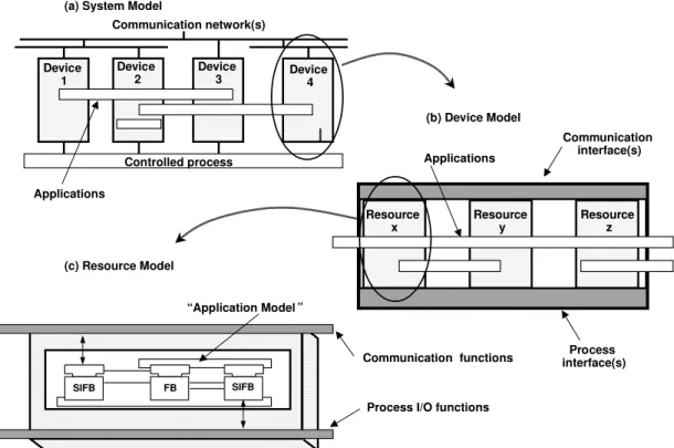
IEC, with the help of several HMS consortium mem-bers, have developed the Function Block Architecture as a new standard to model industrial process control systems using decentralisation and hard real-time de-sign philosophies. The architecture permits access to the controlled manufacturing process via an IEC 61499 system that contains an organisation of devices. The four main models of the IEC 61499 standard are illus-trated in Fig. 1. These models are organised in increas-ing levels of granularity: system model (Fig. 1(a)), de-vice model (Fig. 1(b)), resource model (Fig. 1(c)), and application model (Fig. 1(c)).
A holon is represented by one or more hardware de-vices and can interact via one or more communication networks. As shown in Fig. 1(b), each device com-prises of one or more resources (i.e., processor with memory) and one or more interfaces. Interfaces enable the device to interact with either the controlled manu-facturing process (via a process interface) or with other devices through a communication interface.
Resources are logical entities with independent con-trol over their operations including the scheduling of their tasks. A resource can be created, configured etc. (as part of the system’s life-cycle) via a management model.
Applications (software functional units spanning one or more resources and over one or more devices) are networks of function blocks (FB) and variables con-nected by data and event flows. Such applications aid the modelling of cooperation between the autonomous holons. Function blocks receive events/data from inter-faces, process them by executing algorithms and pro-duce outputs, all handled by an event control chart.
Function blocks’ algorithms can be written in either high-level programming languages (e.g., C++) or in the IEC 61131 languages for programmable controllers (e.g., Ladder Diagrams, Structured Text). A distribu-tion model controls how applicadistribu-tions are decomposed while ensuring that every function block is an atomic unit of distribution.
2.3. IEC 61499 function blocks
An example of an IEC 61499 function block is shown in Fig. 2. As was mentioned previously, the function block can be thought of as an “enhanced” object. Ob-jects can be thought of as entities that do things (i.e., we
Communication network(s)
Controlled process Device
1
(a) System Model
Resource x Communication interface(s) Process interface(s) (b) Device Model FB SIFB SIFB Communication functions
Process I/O functions (c) Resource Model Device 2 Device 3 Device 4 Applications “Application Model ” Applications Resource y Resource z
Fig. 1. The IEC 61499 system, device, resource and application models.
OUTPUTS INPUTS
Event flow Event flow
Data flow Data flow
(Scheduling, communication mapping, process mapping)
Algorithms Type identifier Resource capabilities Instance identifier Execution Control Internal Data
Fig. 2. IEC 61499 function block model.
send a message to them and ask them to perform what they “do”). Function blocks use very specific kinds of messages that are important to the control domain: i.e., events or, in other words, instantaneous occurrences that are used to schedule the execution of the algorithm. As well, data is also passed between function blocks (e.g., messages containing text, floating point numbers, Boolean numbers etc.), which we would expect from a
conventional object.
As one would expect, the function block achieves both algorithmic and data abstraction (algorithms and internal data) typical of a conventional object. Look-ing at the top of the function block though, one can see that events are related to the execution control por-tion of the funcpor-tion block. This porpor-tion of the funcpor-tion block is concerned with scheduling the execution of the function block algorithm’s operations on a resource. When the algorithm has completed its execution, exe-cution control generates zero or more event outputs as appropriate.
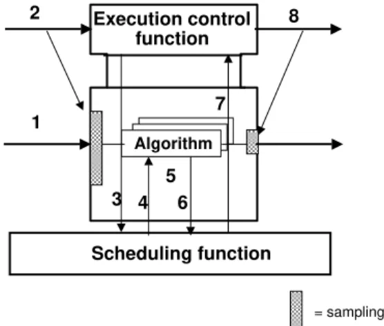
In order to gain a clearer understanding of the IEC 61499 function block, we can look at the data/event synchronisation model shown in Fig. 3. This figure shows at a typical scenario where an event arrives that initiates the execution of an algorithm. The process is synchronised as follows [21]:
1) Relevant input variable values are made available. 2) The event at the event input occurs.
3) The execution control function notifies the re-source scheduling function to schedule an algo-rithm for execution.
4) Algorithm execution begins.
5) The algorithm completes the establishment of values for the output variables.
5 1 3 4 6 2 Execution control function Scheduling function Algorithm = sampling 8 7
Fig. 3. Data/event synchronization model.
6) The resource scheduling function is notified that algorithm execution has ended.
7) The scheduling function invokes the execution control function.
8) The execution control function signals an event output.
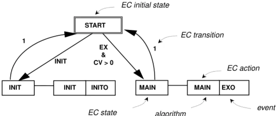
As was noted previously, execution control (EC) is responsible for the synchronisation of the function block. Figure 4 shows an example of an execution con-trol chart (ECC) that is used to specify the sequencing of function block algorithms.
The ECC is included in the execution control block section of the function block and contains one EC initial state and one or more EC states. Each EC state can have zero or more EC actions, which have an associated algorithm and an event to be issued on completion of the algorithm as noted previously. The EC transitions shown in Fig. 4 are associated with a Boolean condition that uses event input variables, input variables, output variables, or internal variables.
For a more detailed discussion of the Function Block Architecture, Brennan and Norrie [4] may be consulted.
3. Extending IEC 61499
In this section we primarily focus on the limita-tions of the IEC 61499 model with respect to achiev-ing automatic configuration and reconfiguration of real-time distributed control systems and propose a general model that is built upon the IEC 61499 concepts to address this issue.
3.1. IEC 61499 and automatic configuration/reconfiguration
The IEC 61499 architecture described in the previ-ous section primarily focuses on models and definitions that allow distributed applications to be developed us-ing function blocks. In particular, IEC 61499 focuses on a precise definition of the function block that shares many of the characteristics of the traditional objects and agents used to develop distributed control appli-cations (e.g., a traditional object focuses on data ab-straction, encapsulation, modularity, and inheritance), but extends this concept (through the identification of data and event flow paths) to include process abstrac-tion and synchronisaabstrac-tion. As a result, this approach is particularly suitable for control of an environment that is concurrent, asynchronous and distributed.
In order to actually create and manage these systems however, further guidance is required. For example, the standard does not provide any guidelines concern-ing the actual implementation of function block ap-plications: e.g., low-level communication protocol re-quirements (e.g., to load, initiate and configure func-tion blocks), how funcfunc-tion blocks are scheduled on re-sources, and how function block applications are com-piled, downloaded and stored [24]. As well, intelli-gent control issues, such as how function block appli-cations can be configured and reconfigured on-the-fly are understandably out of the scope of IEC 61499.
Over the past three years, the authors have been in-volved in various aspects of this work on distributed intelligent control. For example, in [3,40] we report on experiments with a distributed control operating sys-tem (DCOS) to support distributed function block ap-plications. This prototype system was implemented on a distributed PC system consisting of Intel 486 and Pentium processors and was based on the notion of reactive agent architectures [13]. The results showed that our DCOS could support distributed function block applications and meet their basic requirements of con-currency, real-time event-based control. As well, var-ious application configurations were compared (i.e., distributing function blocks across controller nodes in various ways), though the prototype did not support a means of dynamically reconfiguring these applications. As noted previously, the research reported in this pa-per is focused on this issue. In particular, we focus on a model to support intelligent, dynamic reconfigu-ration that is based on IEC 61499 and can be imple-mented on a commercial real-time computing platform in the remainder of the paper. As will be discussed in
1 INIT 1 START EXO MAIN MAIN INITO INIT INIT EX & CV > 0 EC transition EC initial state EC action event algorithm EC state
Fig. 4. An example of an IEC 61499 execution control chart.
the remaining sections, this model is intended to pro-vide a consistent means of managing the configuration of IEC 61499 function block applications. Given that our distributed system is subject to hard and soft real-time constraints, and that it must be implemented on relatively small-footprint platforms typical for embed-ded control, it is implemented with light-weight, reac-tive agents (e.g. [13]). In order to provide the intelli-gent control capabilities that will make the system truly “holonic”, this model will be interfaced with higher-level software agents (e.g., rational agents [32]), as de-scribed in the authors’ work on reconfiguration method-ologies (e.g. [5]), to provide the reasoning capabilities to achieve automatic configuration and reconfiguration.
3.2. A conceptual model for configuration/reconfiguration
Before describing our conceptual model for configu-ration control,1
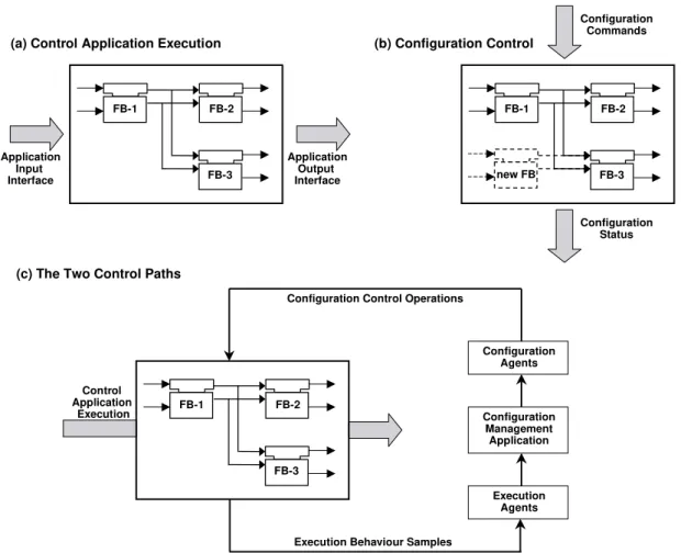
it should be noted that all of the descrip-tions of the models up to this point have been concerned with the execution of distributed control applications in a real-time environment. In particular, when consid-ering IEC 61499 applications, the event and data flow paths determine the order of execution of the function blocks that describe a given distributed control appli-cation. By convention, this application execution con-trol path is represented graphically as a horizontal flow path in IEC 61499 (typically from left to right, though feedback from right to left is permitted) as illustrated in Figs 5(a).
When considering configuration and reconfiguration of function block applications, the authors recognised
1The phrase “configuration control” is used to refer to the
pro-cesses of configuration (e.g., during initial control application set up) and reconfiguration (e.g., when a control application is changed).
that a second control path is required: i.e., a config-uration control path. In order to distinguish this as-pect of a real-time distributed control application from control application execution, we propose modelling configuration control as a vertical (top to bottom) con-trol path as illustrated in Fig. 5(b) (in this case, the “configuration command” is concerned with adding a new function block “new FB”). The resulting concep-tual model is shown in Fig. 5(c). In this figure, the IEC 61499 convention for control application execu-tion flow is retained, while a new configuraexecu-tion control path is introduced.
As will be described in detail in the next section, two new agent types are introduced to help manage config-uration. First, an Execution Agent (EA) is provided that, as its name implies, is primarily concerned with function block execution (e.g., implementing function block functionality, ensuring that function block algo-rithms are scheduled, etc.) but also plays the role of “monitor agent” in the configuration control path as is illustrated in Fig. 5(c). This monitoring capability al-lows the higher-level configuration management appli-cation discussed in the previous section to make deci-sions based on the current state of the execution agents. For example, execution agents can report on the ap-plication’s deadline performance in order to allow the configuration management application decide whether or not function blocks must be redistributed (e.g., be-cause a particular resource is not fast enough or the loading across resources is imbalanced). The second type of agent introduced in our model, the Configu-ration Agent (CA), is primarily responsible for imple-menting the configuration or reconfiguration plans gen-erated by the configuration management application. For example, configuration agents are responsible for creating or deleting function blocks and maintaining inter-function block connections.
FB-2 FB-1 FB-3 Application Input Interface Application Output Interface FB-2 FB-1 FB-3 Configuration Commands Configuration Status new FB FB-2 FB-1 FB-3 Configuration Management Application Configuration Agents Execution Agents Configuration Control Operations
Execution Behaviour Samples Control
Application Execution
(a) Control Application Execution (b) Configuration Control
(c) The Two Control Paths
Fig. 5. Conceptual model for configuration/reconfiguration.
In the next section, we look at this general model more closely, then focus on the details of this approach can be applied to the IEC 61499 basic function block.
4. The reconfiguration model
In this section we begin with a description of the model for configuration control, then describe how this model links with the IEC 61499 function block model.
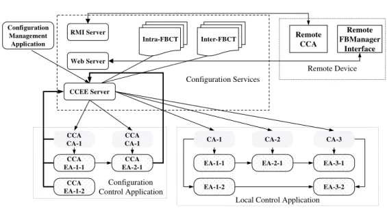
4.1. Configuration control services and support architecture
The architecture for configuration control, shown in Fig. 6, consists of three basic modules to enable control application configuration and reconfiguration: (i) the previously discussed configuration management appli-cation, (ii) a configurations services module, and (iii) a configuration control application. As well, Fig. 6 shows the local control application and a remote
de-vice, where parts of the control application may be dis-tributed or other control applications may be running (i.e., as described in Fig. 1). In the remainder of this sub-section, we will look at each of these aspects of the configuration control architecture.
The local control application, shown in the lower right of Fig. 6 is intended to represent an IEC 61499 function block application. As was noted previously (and will be described in greater detail in the next sub-section), IEC 61499 function blocks (e.g., Fig. 2) are modelled by configuration agents (CA) and execution agents (EA).
Similar to local control applications, the configura-tion control applicaconfigura-tion (CCA) is also modeled by func-tion blocks in our model. The main difference here is that the CCA is a special type of control applica-tion that executes a pre-determined configuraapplica-tion that is provided by the configuration execution engine (de-scribed next). Just as a control application controls the behaviour of physical devices (e.g., robots, CNC ma-chines), the CCA control the behaviour of the control
Remote Device
Local Control Application Configuration Control Application Configuration Services RMI Server Web Server CCEE Server CA-1 EA-1-1 EA-1-2 CA-2 EA-2-1 CA-3 EA-3-1 EA-3-2 CCA EA-1-1 CCA EA-1-2 CCA CA-1 CCA EA-2-1 Remote CCA Remote FBManager Interface Intra-FBCT Inter-FBCT Configuration Management Application CCA CA-1 CA – Configuration Agent EA – Execution Agent
CCA – Configuration Control Application CCEE – Configuration Control Execution Engine FBCT – Function Block Connection Table
Fig. 6. Configuration control services and support architecture.
application. In other words, the CCA can be thought of as a meta-control application that is responsible, for example, for how function blocks in the local control application are interconnected.
The configuration services module shown in Fig. 6 acts as an interface between this meta-control appli-cation and the higher-level configuration management application, where configuration and reconfiguration plans are developed. As well, since control applica-tions exist in a distributed environment, it also serves as an interface to other devices.
The key elements of the configuration services mod-ule are the configuration control execution engine (CCEE) and the connection tables (intra-function block connection table (intra-FBCT) and inter-function block connection table (inter-FBCT)). The CCEE basically completes the loop shown in Fig. 5(c): i.e., it monitors the status of execution agents (and reports this infor-mation to the configuration management application) and relays the configuration commands (from the con-figuration management application) to the configura-tion agents. To enable the CCEE to convert higher-level configuration commands from the configuration management application (e.g., “connect function block ADC1 to function block PID3 on RESOURCE2”), the CCEE relies on two sets of tables that describe the con-nections within function blocks (intra-FBCT) and the connections between function blocks (inter-FBCT).
Finally, configuration and reconfiguration can be managed across distributed devices either automati-cally (i.e., invoked by a remote device’s CCA) or man-ually through a Remote Function Block (FB) Man-ager Interface. The configuration services provided to support these two modes of configuration are mote method invocation (RMI) and web services re-spectively.
As noted previously, the key to achieving intelli-gent reconfiguration (i.e., multi-aintelli-gent techniques that enable the system to reconfigure automatically in re-sponse to change) with this model lies in the configu-ration management application. A detailed discussion of this application is beyond the scope of this paper however, for the remainder of this section we described two approaches to configuration management that have been investigated by the authors (e.g. [5]): (i) a pre-programmed or “contingencies” approach, and (ii) a soft-wiring approach.
For example, with the first form of configuration con-trol, contingencies are made for all possible changes that may occur. In other words, alternate configurations are pre-programmed based on the system designer’s un-derstanding of the current configuration, possible faults that may occur, and possible means of recovery.
With this approach, the configuration management application uses pre-defined reconfiguration tables that make use of the intra-FBCT and the inter-FBCT tables
described above. For example, in the event of a device failure, the affected portions of an application could be moved to different devices by selecting an appropriate reconfiguration table. As well, this detailed representa-tion of the funcrepresenta-tion block interconnecrepresenta-tions would allow higher-level agents to access the information required to make a smooth transition from one configuration to another, thus enabling dynamic reconfiguration.
The main disadvantage of the contingencies ap-proach is that it is inflexible, particularly with respect to handling unanticipated changes. As well, this ap-proach would require constant maintenance in order to keep the reconfiguration tables current: i.e., each change would require a change to the reconfiguration tables.
The basic idea behind the second approach to recon-figuration is to take advantage of higher-level reasoning agents to analyse the current configuration and plan for reconfiguration when required. Ideally, we are striving for an “integrated circuit” approach where fine grain components can be “plugged-in”. Similar to Sun’s Jini approach, this approach uses the directory services of the intra-FBCT and the inter-FBCT as well as the un-derlying configuration agents that handle the “wiring” between components.
The primary advantage of this approach is its po-tential to overcome the inflexibility of the contingen-cies approach as well as its potential to realise intelli-gent reconfiguration. For further details of these two approaches to reconfiguration please see [5].
4.2. Configuration control and the function block model
The IEC 61499 standard specifies a control compo-nent model at the logical level. It also defines gen-eral principles for the specification of types and the behaviour of instances of service interface function blocks, including management function blocks. As well, the command syntax for configuration control is specified. However, the standard does not specify mod-els for function blocks to support runtime reconfigura-bility. Based on the requirements of a holonic con-trol system noted previously, the authors have designed a multi-agent model for basic and composite function blocks to support runtime reconfigurability.
Given that function blocks, like holons, are recursive, the basic function block (BFB) model that is described in this sub-section is equally applicable to IEC 61499 composite function blocks and sub-applications [21].
To model the configuration process and component interaction for function blocks, the IEC 61499 model must be combined with other modelling approaches to specify and verify the execution process and recon-figuration process concurrently. Several models have been proposed in recent years to describe real-time em-bedded software [10]. Since many emem-bedded systems deal with safety-critical applications, formal specifica-tion and verificaspecifica-tion are highly desired and widely used in software development, such as StateChart [17], Net Condition Event System [35], Coloured PetriNet [41], etc.
It is also recognised that a disadvantage of using formal methods to specify a system is that an executable system cannot be constructed after specifications are done, and the implementation can introduce additional errors even if the specifications have been proven to be correct [10].
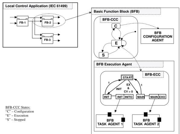
To model IEC 61499 function block based control components with concurrent configuration control, we combine the function block model with the Hierarchi-cal Finite State Machine (HFSM) model to generate a concurrency model from the software architecture point view as shown in Fig. 7.
In this figure, basic function blocks are modelled as follows. First, the function block’s control function-ality (i.e., how it is expected to behave in the control application) is encapsulated in execution agents, which have a direct correspondence with the basic function block model shown in Fig. 2. For example, the IEC 61499 ECC (execution control chart) is represented by the execution agent’s basic function block ECC (BFB-ECC); the IEC 61499 function block algorithms and internal data are encapsulated in EA task agents. One form of representation for the execution agent that has been suggested by the authors [15] is to use the real-time unified modelling language (RT-UML) “capsule” stereotype (the symbols used for the BFB task agents in Fig. 7 correspond to the symbol for RT-UML capsules). This model allows state machines to be modelled ex-plicitly and also supports a recursive structure.
As noted previously, configuration agents manage function block configuration. This is illustrated graphi-cally in Fig. 7 by the BFB configuration agent. In order to manage which agent (EA or CA) is executing, or in other words, whether the function block is in the exe-cution or configuration flow path (i.e., Fig. 5), an addi-tional state machine is used: the basic function block configuration control chart (BFB-CCC). This state ma-chine can be in one of three states: configuration (“C”), execution (“E”), or stopped (“S”). In the
“configura-FB-2 FB-1
FB-3
Local Control Application (IEC 61499)
1 INIT 1 STA RT EXO MAIN MAIN INITO INIT INIT EX & CV > 0 BFB TASK AGENT 1 BFB Execution Agent BFB-ECC C S E BFB CONFIGURATION AGENT Basic Function Block (BFB)
BFB-CCC BFB TASK AGENT 2 BFB-CCC States: “C” – Configuration “E” – Execution “S” – Stopped
Fig. 7. Hierarchical Finite State Machine (HFSM) model.
tion” state, the BFB-CA is running and performing configuration commands that are based on messages received from the CCEE. In the “execution” state, the BFB-EA runs, allowing the function block to perform its control application functionality. Finally, the func-tion block can be placed in a stopped state if required (e.g., prior to a configuration change).
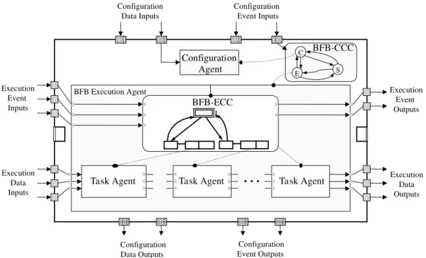
Figure 8 illustrates how this approach fits into the IEC 61499 basic function block model. As noted in Section 2, IEC 61499 control flow runs from left to right by convention. This convention is shown by the event and data inputs and outputs flowing from left to right through the execution agent in Fig. 8. Like the standard IEC 61499 model shown in Fig. 2, event I/O is associated with the execution control chart (i.e., BFB-ECC in Fig. 8) and data I/O is associated with internal data and algorithms (i.e., encapsulated in the task agents in Fig. 8).
The main modification to the basic function block model is the introduction of event and data flow in the new configuration control flow path described previ-ously. In direct parallel to our control execution flow path, configuration event inputs and outputs are asso-ciated with the configuration control execution
con-trol chart (i.e., BFB-CCC in Fig. 8), while configura-tion data inputs and outputs are associated with one or more configuration agent. The reason that both data and event I/O are used in the configuration control path is that configuration and reconfiguration of function blocks is managed by the configuration control appli-cation (CCA) described in the previous sub-section. As noted previously, this application is also a function block application.
5. Implementing the configuration control model
In this section we provide an example of how our model to support configuration control has been imple-mented in real-time Java. We start with a brief descrip-tion of the applicadescrip-tion environment, and then provide an example of a common proportional-integral-derivative (PID) controller application.
5.1. The application environment
As noted previously, our earlier work on a real-time distributed control prototype involved developing
Configuration Agent BFB-CCC E C S Configuration Data Inputs Configuration Event Inputs Execution Event Outputs Configuration Data Outputs Configuration Event Outputs BFB-ECC
Task Agent Task Agent
…
Task AgentBFB Execution Agent Execution Data Outputs Execution Event Inputs Execution Data Inputs l
Fig. 8. The basic function block model.
a prototype real-time distributed operating system to support distributed IEC 61499 function block applica-tions (e.g. [3,40]). Given the recent advances in both hardware and software for distributed applications, we chose to use a commercially available system to test our configuration control model.
For software development, we chose Java, because of its broad popularity, simplified object model, strong notions of safety and security, as well as its multithread-ing support. Of course, Java has not had a history of use in real-time embedded systems because of its large size, non-deterministic behaviour, and scheduling performance. Recently however, there has been con-siderable progress in the development of Java-based microprocessors [25] and Java real-time kernels [12] that have made real-time embedded Java-based system more of a reality.
Currently, there are three main approaches for real-time Java: (i) work towards a new Java specification of a real-time Java virtual machine [33], (ii) a Java chip for directly executing Java code with real-time perfor-mance [1], and (iii) combing the Java virtual machine with a real-time operating system kernel to supply an integrated real-time Java kernel [12]. For our work, we chose the third approach based of our experience with real-time operating systems and chose the Jbed operating system implemented on a single PowerPC 823e [20].
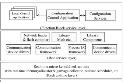
The Jbed operating system is designed to support the safe composition of components, objects, and tasks. This modular design allows components, such as the basic function block component described in Figure 8, to be loaded on demand. As well, full control over task execution is provided (e.g., multitasking sched-uler, memory allocator, garbage collector, and excep-tion handling control), to allow applicaexcep-tions’ real-time constraints to be met.
In order to develop real-time Java applications, a target byte-code compiler (TBCC) is provided. This flash compiler can download Java byte code from a network link, serial line, or EPROM and compiles it directly into RAM [12]. Flash compilers like Jbed’s TBCC delay compilation, but only until load-time, not until run-time as just-in-time (JIT) compilers do. This avoids the speed and size overhead of an interpreter and the long latencies when calling some code for the first time. As a result, flash compilers provide the best solution for embedded real-time systems.
Finally, Jbed supplies a mechanism to use a hard real-time garbage collection algorithm that does not block time-critical tasks, i.e., it can be pre-empted anytime. This is important because unlike memory allocation, garbage collection is not under direct control of the programmer. The collector runs as a background thread with lower priority than all the time-critical tasks. The main goal of the Jbed memory manager was to make
PowerPC CPU, Peripheral devices, Communication devices (Hardware layer)
Real-time micro kernel/Jbed run-time
with real-time memory allocator& garbage collector, real-time scheduler, etc. (Jbed run-time layer)
Communication device drivers Communication device drivers Process I/O framework Communication framework Network loader & flash compiler
Library Math etc. Library Components Configuration Services Local Control Applications
(Jbed service layer) (Function Block service layer)
Configuration Control Application
Fig. 9. The Jbed-based implementation.
(a) PID_CALC Basic Function Block Ty pe (b) PID_CALC and INTEGRAL_REAL Function Block Application
PID_CALC-1 INTEGRAL_REAL-1
(d) inter-FB Configuration Table
FB Name : (String) PID_CALC-1 PID_CALC-1 PID_CALC-1 PID_CALC-1 …
Port Name : (String) INITO PREO ETERM Null …
FB Name : (String) INTEGRAL_REAL-1 INTEGRAL_REAL-1 INTEGRAL_REAL-1 INTEGRAL_REAL-1 …
Port Name : (String) INIT EX XIN Null …
(c) intra-FB Configuration Table
FB Name : (String) PID_CALC-1 PID_CALC-1 PID_CALC-1 PID_CALC-1 PID_CALC-1 …
Execution Agent ID : (int) 2 3 4 Null Null …
Port Name : (String) INIT PRE POST ETERM XOUT …
Event ID : (int) 3 4 5 Null Null …
Data Type 1 Output Port ID : (int) Null Null Null 1 2 … Data Type 2 Output Port ID : (int) Null Null Null Null Null
…
Fig. 10. A PID control application.
sure that garbage collection for non-time-critical tasks cannot interfere with time-critical tasks.
In order to test our approach, the Jbed-based Java development and execution environment is used as a platform to implement an experimental prototype of the configuration control model described in the previous
section. Figure 9 provides an overview of Jbed-based controller structure to implement this experiment pro-totype. As can be seen in this figure, our configura-tion control model sits at the “applicaconfigura-tion level” and is supported by basic Jbed services (i.e., compiling, class libraries, communication and I/O drivers), and the Jbed
int DURA=10; // Tas k Duration int ALLO=0; // Tas k Allowance int DEAD=30; // Task Deadline
1 Get real-time event’s id number e=getEVENTid();
2 Create real-time event “e” event[e]=new UserEvent(); 3 Get execution agent’s ID number f=getFBid();
4 Create this real-time execution agent “f”
try { fbtask[f]=new Task(new PID_CALC_1("INIT"),DURA, ALLO, DEAD, event[e]); } catch (Exception e) { java.lang.System.out.print(e);}
5 insert port items into intra-FBCT
Set_intra_FBCT(getFBint("PID_CALC_1"), f, getPortint("INIT"), e, 0, 0, 0); 6 Start execution agent “f” (ready to be triggered)
fbtask[f].start();
// end of EA creation
Fig. 11. Execution agent creation.
PID_CALC-1
public void createCONNECT(String PortName, int e) {
if (PortName=="INITO") { eINITO=e;} else if (PortName=="PRE") { ePREO=e;} }
CCEE ConfigAgent.createCONNECT (String PortName, int e)
CA EA INITO eINITO ePREO INTEGRAL_REAL-1 EA INIT eINIT eEX EA EX Event [eINIT].trigger EA PREO CA
Fig. 12. Inter-connecting function blocks (event connections).
real-time micro-kernel. As noted above, a PowerPC 823e is used for hardware support.
5.2. A worked example
In this section we provide an example of a sim-ple PID control application that consists of two IEC
61499 basic function block types: PID CALC (cal-culates the “proportional” and “derivative” terms) and INTEGRAL REAL (calculates the “integral” term). Figure 10 shows the local control application (Fig. 10(b)) and also provides examples of the intra-FBCT (Fig. 1(c)) and the inter-intra-FBCT (Fig. 1(d)).
PID_CALC-1
public void createCONNECT(String PortName, int iData) {
if (PortName==“iETERM") { iETERM=iData;} }
CCEE
ConfigAgent.createCONNECT (String PortName, int iData) CA
EA INITO iData EA PREO INTEGRAL_REAL-1 CA EA INIT ido [iHOLD] ido [iXIN] EA EX ido [iXIN] iETERM
Fig. 13. Inter-connecting function blocks (data connections).
As noted previously, the intra-FBCT is concerned with the connections within the function blocks. In this case, Fig. 10(c) provides a detailed list of the con-nections within a specific instance of the PID CALC function block type shown in Fig. 10(a) (i.e., instance “PID CALC-1”). For example, the execution agent ID’s and their associated ports are listed: i.e., “Port Name” and “Event ID” (in the case of event ports) and “Data Type” (in the case of data ports). Similar in-formation is also provided concerning the task agent and configuration agent connections. As well, the table lists all function block instances in the local control application (i.e., in this case it lists “PID CALC-1” and “INTEGRAL REAL-1”).
The inter-FBCT provides a listing of all of the nections between function blocks in the local con-trol application. For example, the second column of Fig. 10(d) lists the event connection “INITO” (out-put of “PID CALC-1”) to “INIT” (in(out-put of “INTE-GRAL REAL-1”). In order to support run-time recon-figurability, these tables are programmed in an array structure and managed with a vector object structure. By maintaining these object structures centrally in the controller, the reconfiguration process is kept fast and simple.
In order to initialise these tables, the function block’s configuration agent first creates the appropriate execu-tion agents. The Java code for this process is shown in Fig. 11. Before describing the steps in this figure, it should be noted that, within each execution agent, task agents are associated with events. For example, in Fig. 7 when event “INIT” is true, state “INIT” is active and “Task Agent 1” runs. The direct parallel in the IEC 61499 function block model is illustrated in Fig. 4: i.e., when state “INIT” is reached, algorithm “INIT” executes. As a result, the first three steps of the execution agent creation process involve (1) getting a unique real-time event ID number for each function block event input (only one event is shown in this fig-ure), (2) creating a real-time event for each function block event input, and (3) getting a unique execution agent ID number.
In the next step, when the execution agent is created, the events are assigned to task agents. The real-time task agent “fbtask[f]” is present in the object “Task” with real-time constraint parameters DURA (task dura-tion), ALLO (task allowance), and DEAD (task dead-line), and is associated with the real-time event object “event[e]”. Other agents can now use the command, “event[e].trigger” to trigger “Task”. We use the Java
Fig. 14. Function block manager interface.
reflection mechanism to facilitate run-time reconfigu-ration between “Task” and “event[e]”.
As noted previously, internal function block event connections and data connections are maintained in the intra-FBCT. Step 5 of Fig. 11 inserts the new task agent and event object connection data in this example. Once all of the event objects and task agents are created and registered in the intra-FBCT, the execution agent is ready to run (i.e., step 6 of Fig. 11).
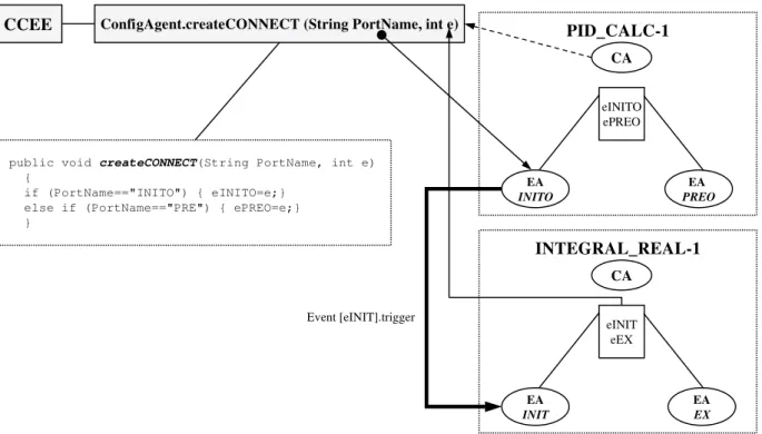
At this point, we have described the structure of the function block connection tables, inter-FBCT and intra-FBCT, as well as how individual function block instances are created and the intra-FBCT is updated. The final stage involves establishing connections be-tween function block instances in order to create the local control application, as well as the associated updates of the inter-FBCT. Figures 12 and 13 show how function block event and data connections are established respectively. For example, in Fig. 12 a configuration agent establishes the event connec-tion “INITO” (output of “PID CALC-1”) to “INIT” (input of “INTEGRAL REAL-1”) noted previously. In this case, PID CALC-1’s configuration agent cre-ates a connection for its event port “INITO” (i.e., PortName = “INITO”) and associates it with INTE-GRAL REAL-1’s event port “INIT” and its real-time
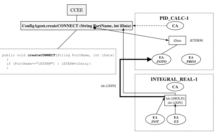
event “eINIT”. Once this connection is established, an event at PID CALC-1’s “INITO” output event port will cause INTEGRAL REAL-1’s execution agent (EA) to perform whatever behaviour is associated with its event “eINIT” (e.g., an initialisation algorithm). Sim-ilarly, Fig. 13 shows the process for data connec-tions. In this case, the connection is being made be-tween PID CALC-1’s “ETERM” data output, and IN-TEGRAL REAL-1’s “XIN” data input.
At this stage the local control application is ready to run on the device (i.e., the execution agents have been created) and the configuration control services are ready to be used by a configuration application (e.g., a con-figuration management application as shown in Fig. 6). An example of this is provided in Fig. 14. In this case, we show the terminal interface to the PowerPC (run-ning RPX Lite) and our Function Block Manager in-terface implemented on a web browser. The inin-terface allows function blocks to be manually configured (i.e., both intra- and inter- function block connections) and the event and data connections to be tested. Our tests have shown that this approach allows small function block applications like the one described in this sec-tion to be quickly and easily configured and reconfig-ured at run time. Of course, to achieve a truly holonic system, as described in Section 1, further experimental
work is required with larger applications and automatic reconfiguration mechanisms.
6. Conclusions and future research
In this paper we have described a concurrent func-tion block model to control the run-time reconfigura-tion process of a real-time holonic controller. A key aspect of this model is its use of a hierarchical reconfig-uration management that specifies two concurrent con-trol paths: (i) concon-trol of the process, and (ii) config-uration control (i.e., software concerned with manag-ing application configuration and reconfiguration). As well, we described a real-time java implementation to support function block-based real-time task execution and run-time reconfigurability.
At the current stage of development, this approach provides a framework to support intelligent reconfigu-ration, but does not yet realise this holonic manufactur-ing systems goal of automatic and dynamic adaptabil-ity. In order to develop appropriate methodologies for reconfiguration, we have been following a sequential approach with our research [5], focused on increasingly “sophisticated” levels of reconfiguration: i.e., simple, dynamic and intelligent reconfiguration. For example, simple reconfiguration involves evaluating the utility of using the IEC 61499 model for reconfiguration (e.g., to avoid software coupling issues during reconfiguration). With dynamic reconfiguration, our focus has been on the development of techniques to properly synchronise software during reconfiguration. Tests with our pro-totype real-time distributed operating system [3,40] as well as our recent tests with the system reported in this paper have already made considerable progress towards these two forms of reconfiguration. Our recent work has been focused on the highest level of reconfigura-tion, intelligent reconfigurareconfigura-tion, and in particular, how multi-agent techniques can be used to allow the system to reconfigure automatically in response to change.
References
[1] aJile Systems, Website, http://www.ajile.com/, 2002. [2] A. Baker, H. Parunak and K. Erol, Agents and the internet:
in-frastructure for mass customisation, IEEE Internet Computing
3(5) (1999), 62–69.
[3] S. Balasubramanian, R.W. Brennan and D.H. Norrie, An ar-chitecture for metamorphic control of holonic manufacturing systems, Computers in Industry 46(1) (2001), 13–31.
[4] R.W. Brennan and D.H. Norrie, Agents, holons and function blocks: distributed intelligent control in manufacturing,
Jour-nal of Applied Systems Studies Special Issue on Industrial Ap-plications of Multi-Agent and Holonic Systems 2(1) (2001), 1–19.
[5] R.W. Brennan, M. Fletcher and D.H. Norrie, An agent-based
approach to reconfiguration of real-time distributed control systems,submitted to: IEEE Transactions on Robotics and Au-tomation, Special Issue on Object-Oriented Distributed Con-trol Architectures, 2002.
[6] S. Bruckner, J. Wyns, P. Peeters and M. Kollingbaum, Design-ing agents for manufacturDesign-ing process control, ProceedDesign-ing of
Artificial Intelligence and Manufacturing Research Planning Workshop,1998, pp. 40–46.
[7] S. Bussmann and J. Sieverding, Specification of holonic agent control concepts in manufacturing logistics, Deliverable D7.3-1 of HMS Consortium, 2000.
[8] M. Cutkosky, R. Englemor, R. Fikes, T. Gruber, M. Gene-sereth, W. Mark, J. Tenenbaum and J. Weber, PACT: an ex-periment in integrating concurrent engineering systems, IEEE
Computer 26(1) (1993), 28–37.
[9] T. Darr and W. Birmingham, An attribute-space representation and algorithm for concurrent engineering, AI EDAM 10(1) (1996), 21–35.
[10] B. Douglass, Doing hard time: Developing real-time
sys-tems with UML, objects, frameworks, and patterns, Addison-Wesley, 1999.
[11] C. Duarte and T. Maibaum, A rely-guarantee discipline for open distributed system design, Information Processing
Let-ters 75(2000), 55–63.
[12] Esmertec, Jbed RTOS Package User Manual, Esmertec, Inc., 2000.
[13] J. Ferber, Reactive distributed intelligence: principles and ap-plications, in: Foundations of Distributed Artificial
Intelli-gence,G. O’Hare and N. Jennings, eds, Wiley Interscience, 1996, pp. 287–314.
[14] M. Fletcher and R.W. Brennan, Designing holonic manufac-turing systems using the IEC 61499 (function block) architec-ture, IEICE/IEEE Joint Special Issue on Autonomous
Decen-tralized Systems and Systems’ Assurance E84-D(10) (2001), 1398–1401.
[15] M. Fletcher, R.W. Brennan and D.H. Norrie, Design and eval-uation of real-time distributed manufacturing control systems using UML Capsules, 7th International Conference on
Object-oriented Information Systems,2001, pp. 382–386.
[16] M. Fox, J. Chionglo and M. Barbuceanu, The integrated supply
chain management system, Internal Report, Department of Industrial Engineering, University of Toronto, 1993. [17] D. Harel, Statecharts: a visual formalism for complex systems,
Scientific Computer Programming 8(1987), 231–274. [18] T. Heikkila, M. Jarviluoma and T. Juntunen, Holonic control
for manufacturing systems: design of a manufacturing robot cell, Integrated Computer-Aided Engineering 4 (1997), 202– 218.
[19] Holonic Manufacturing Systems Consortium, Holonic manu-facturing systems overview, Holonic Manumanu-facturing Systems Consortium Web Site, http://hms.ifw.unihannover.de/, 2002. [20] J. Hoskins and J. Blackledge, Exploring the PowerPC
Revo-lution,Maximum Press, 1995.
[21] International Electrotechnical Commission, IEC TC65/WG6, Voting Draft: Function Blocks for Industrial Process-Measurement and Control Systems, Part 1 Architecture, Inter-national Electrotechnical Commission, 2000.
[22] K. Lam, G. Law and V. Lee, Priority and deadline assignment to triggered transactions in distributed real-time databases,
Systems and Software 51(2000), 57–65.
[23] R. Lewis, Programming Industrial Control Systems Using IEC
1131-3,IEE, London, 1996.
[24] R. Lewis, Modelling Control Systems Using IEC 61499:
Ap-plying Function Blocks to Distributed Systems,IEE, London, 2001.
[25] D. Loomis, The TINI Specification and Developer’s Guide, Addison-Wesley, 2001.
[26] A. Lyons, UML for real-time overview, technical report of ObjecTime Ltd., 1998.
[27] F. Maturana and D.H. Norrie, Multi-agent mediator architec-ture for distributed manufacturing, Journal of Intelligent
Man-ufacturing 7(1996), 257–270.
[28] H. Park, J. Tenenbaum and R. Dove, Agile infrastructure for manufacturing systems: a vision for transforming the US man-ufacturing base, Defense Manman-ufacturing Conference, 1993. [29] H. Parunak, Manufacturing experience with the contract net,
in: Distributed Artificial Intelligence, M.N. Huhns, ed., Pittman, 1987, pp. 285–310.
[30] H. Parunak, RAPPID project index page, http://www.iti.org/ cec/rappid/, 1997.
[31] Y. Peng, T. Finin, Y. Labrou, B. Chu, J. Long, W. Tolone and A. Boughannam, A multi-agent system for enterprise integration,
Proceedings of PAAM’98, 1998, pp. 533–548.
[32] A. Rao and M. Georgeff, An abstract architecture for rational agents, Proceedings of Knowledge Representation and
Rea-soning,1992, pp. 439–449.
[33] The Real Time Java Expert Group, The Real-time Specification
for Java,Addison-Wesley, 2000.
[34] J. Sieverding, Specification of manufacturing test missions, Deliverable D7.5-2 of HMS Consortium, 2000.
[35] R.S. Sreenivas and B.H. Krogh, On condition/event systems with discrete state realizations, Discrete Event Dynamic
Sys-tems: Theory and Applications 2(1) (1991), 209–236. [36] P. Valckenaers and H. Van Brussel, IMS TC5: holonic
manufacturing systems technical overview, Holonic Manu-facturing Systems Consortium Web Site, http://hms.ifw.uni-hannover.de/, 1994.
[37] H. Van Brussel, J. Wyns, P. Valckenaers, L. Bongaerts and P. Peeters, Reference architecture for holonic manufacturing systems: PROSA, Computers in Industry 37 (1998), 255–274. [38] V. Vyatkin and H. Hanisch, Bringing the model-based verifi-cation of distributed control systems to the engineering prac-tice, VI IFAC Workshop on Intelligent Manufacturing Systems (IMS’2001), 2001, pp. 152–157.
[39] L. Wang, R.W. Brennan, S. Balasubramanian and D.H. Nor-rie, Realizing holonic control with function blocks, Integrated
Computer-Aided Engineering 8(1) (2001), 81–93.
[40] X. Zhang, S. Balasubramanian, R.W. Brennan and D.H. Nor-rie, Design and implementation of a real-time holonic control system, Information Science Special Issue on Computational
Intelligence for Manufacturing 27(1–2) (2000), 23–44. [41] B. Zhou, L. Wang and D.H. Norrie, Design of distributed
real-time control agents for intelligent manufacturing systems,
Proceedings of the 2nd International Workshop on Intelligent Manufacturing Systems,1999, pp. 237–244.