Casting a One-Lunger Atlantic Marine Engine
by
Samantha Nicole Castellanos
Submitted to the
Department of Mechanical Engineering
in Partial Fulfillment of the Requirements for the Degree of Bachelor of Science in Mechanical Engineering
at the
Massachusetts Institute of Technology
June 2016 MASSACHUSETTS INSTITUTE OF TECHNOLOGY
JUL 08 2016
LIBRARIES
ARCHIVES
C 2016 Massachusetts Institute of Technology. All rights reserved.Signature of Author:
Signature redacted
Department of Mechanical Engineering May 6, 2016
Certified by:
Signature redacted
Daniel Braunstein Pappalardo Director Thesis Supervisor
Accepted by:
Signature redacted
Anette Hosoi Professor of Mechanical Engineering Undergraduate Officer
Casting a One-Lunger Atlantic Marine Engine
by
Samantha Castellanos
Submitted to the Department of Mechanical Engineering on May 9, 2016 in Partial Fulfillment of the
Requirements for the Degree of
Bachelor of Science in Mechanical Engineering
ABSTRACT
Fabrication of a one-lunger Atlantic marine engine for the purposes of developing a curriculum for an advanced fabricating and machining class for the Papplardo Apprentices at MIT. One-lunger marine engines greatly influenced the fishing cultures of Nova Scotia at the turn of the
2 0' century. Discussion of proper casting practices and terminology in addition to theory of sand
types, machinability, engine cycles, and ignition systems. In depth descriptions of basic and advanced casting processes using the ignitor body and piston as examples.
Thesis Supervisor: Daniel Braunstein Title: (Pappalardo Director
Table of Contents
1 Introduction ... 1
2 Atlantic One-Lunger Engine Cycle: 2-Stroke ... 2
3 Ignition System s ... 3
3.1 M ake and Break ... 3
3.2 Ignition M agneto...4
4 Material Castability and Pouring Temperatures... 5
5 M achinability and M aterial Selection ... 8
6 Basic Foundry and Casting Term s... 11
7 Types of Casting Sand ... 12
7.1 Green Sand...12
7.2 Resin Sand...14
8 Prepping Part CAD and Model for Casting... 15
8.1 Before prepping your CAD model for casting: ... 15
8.2 Prepping the CAD m odel for casting: ... 15
8.3 Creating the Pattern ... 17
9 Casting the Part: Basic Green Sand Casting ... 17
10 Casting the Part: Advanced - Shell Casting the Piston ... 22
10.1 First Attem pt... 23
10.2 Second Attem pt... 26
10.3 Third Attem pt... 30
11 Curriculum Suggestions... 37
12 Conclusion ... 39
A cknow ledgm ents ... 39
List of Figures
Figure 1: Cover for the Lunenburg Foundy Marine Equipment Catalog [2]...1
Figure 2: Cycle of a 2-stroke one-cylinder combustion engine [7]...3
Figure 3: "Make and break" circuit schematic [4]. Note the inductor is in series with a battery. When the igniter points break, the inductor attempts to create continuous current by creating an arc at the points... 4
Figure 4: Schematic of the Wico Model EK Magneto [5]. The armature is moveable and completes and breaks the magnetic circuit. Changing magnetic fields induce currents in the coils and ultimately a spark ... 5
Figure 5: Picture of the Wico Model EK Magneto that was used in a Universal Fish erm an on e-lu n ger...5
Figure 6: Varying strength of green sand mixed with various percentages of southern bentonite and water. Peaks indicate the temper point. [8] ... 13
Figure 7: Cope is placed on the floor, top side down. The floor and pattern are p ow d ered ... 1 7 Figure 8: Top half of part is placed on the parting surface...18
Figure 9: A dowel is placed to form the sprue and the cope is filled and ramiped with san d in lay ers...1 8 Figure 10: Once the cope is fully filled and rammed, a straight edge is used to scrape off excess san d ... 19
Figure 11: Cope is flipped over and powdered with talc... 19
Figure 12: Drag is packed and rammed with sand... 20
Figure 13: The part is removed from the sand with the help of a tapped screw...20
Figure 14: Cope is placed on top of drag and clamped prior to pouring...21
Figure 15: After metal has been poured and the part has cooled it is removed from th e sa n d ... 2 1 Figure 16: Full cast of piston with sprue still attached... 22
Figure 17: Mold for piston core (left) and piston pattern (right)... 23
Figure 18: Core print made of resin sand, first attempt... 24
Figure 19: The piston pattern in placed in the flask and the flask is filled and ram m ed w ith san d ... 2 5 Figure 20: Molten iron is poured into the flask and flames appear from the top. The cast did not appear to fill fully ... 25 Figure 21: The failed piston. The core collapsed and the iron filled the hollow part of th e co re p rin t...2 6
Figure 22: Second attempt at creating the core print. The mold is filled fully with sand using a copper tube to create a vent in the middle... 26 Figure 23: Pattern of the piston. The seams were plastered and sanded to make it easier to rem ove the pattern from the sand... 27 Figure 24: Attempt at creating a shell mold for the pattern. The resin sand cured too quickly and was difficult to secure to the vertical sides of the pattern... 28 Figure 25: The shell broke apart only leaving the part surrounding the aligning featu re in ta ct... 2 8 Figure 26: Left -the cope after the pattern was removed, leaving behind the cavity that would create the piston. Center -the flask is lowered onto the base flask and the
core print is aligned. Right -the resulting cast piston. It did not fill with metal fully. ... 2 9 Figure 27: Cavity of the second attempted piston. The surface finish is good aside from some flash and disturbances near the bosses... 30
Figure 28: A small box was created in order to attempt a full shell casting of the piston. The pattern is placed in the box and filled with resin sand... 30
Figure 29: The moustache feature was stuck in the resin sand and broke off when the pattern was being rem oved from the shell... 31 Figure 30: The moustache feature of the piston was epoxied to the pattern. The top was then plastered to fill in any holes and sanded to smooth out the surface...32 Figure 31: The shell casting of the piston fell apart at the boundary between resin sand layers. The first two layers were salvaged and only covered the alignment featu re of th e p attern ... 33 Figure 32: The core print was cantilevered into the flask and then the flask was m oved onto the base and iron was poured... 34 Figure 33: Excavating the piston. ... 34
Figure 34: Full cast of the piston (left) and the cavity (right). The finish of the piston
cav ity is ex cellen t... 3 5 Figure 35: A void appeared on the piston. It is located in the vicinity of the piston rings so it should be mostly bored out and should not affect the piston performance. ... 3 6 Figure 36: The difference in surface finish can be seen. The left side is where green sand met the pattern, the right side is where resin sand met the pattern... 36
1 Introduction
Look back 150 years and try to imagine the magnitude of excitement and revolution surrounding the boom of the internal combustion engine. The people were in awe. After George Bailey Brayton invented the first safe and practical oil engine in 1872, the American congress foresaw the profound revolution that the internal combustion engine would bring and thought it to be a more revolutionary development "'than the invention of the wheel, the use of metals, or the steam engine.' " [1]. To put it in perspective, the invention is just as revolutionary as landing on the moon in 1969 or the successful development of human-like artificial intelligence would be in the world we live in today.
By the beginning of the 20th century, gas engines were being created by an estimated 10,000 individual manufacturers all across America [1], and the one-lunger (one
cylinder engines) that were used in the fishing cultures of northeastern America greatly influenced those communities. Today, finding one of those engines is a rare event -but this thesis seeks to revive some of the glamour of the past by creating the first CAD model of an Atlantic One-Lunger Marine Engine and fabricating a new one from scractch. The Atlantic Marine Engine was originally manufactured by the Lunenburg Foundry in Nova Scotia, the only surviving company who built two-cycle marine engines [1]. The foundry is also celebrating their 125th anniversary this year.
Figure 1: Cover for the Lunenburg Foundy Marine Equipment Catalog [2].
The motivation for this paper was to develop a curriculum for a senior advanced fabrication and machining class for the MIT Pappalardo apprenticeship program. The
program selects about 6 juniors, who begin learning more about advanced machining through the fabrication of a small stirling engine. Juniors also learn about speeds and feeds, various tool applications, and how to use indicators for quality control. Juniors who return to the program as seniors then complete an advanced fabrication and machining project, such as is described here. The senior apprentices attempt to build a full scale engine, this first year it was a 2-stroke Atlantic marine engine, and in doing so the apprentices learn complex casting techniques in addition to more machining skills. At any given time, there are about 6 juniors and 6 seniors in the apprenticeship program. In addition to developing machining skills, apprentices are expected to teach and assist sophomores in their first design and manufacturing class, which consists of a robotic competition. Inspiring others to learn about mechanical engineering and proper fabrication techniques while maintaining well-being and happiness is also a vital role of the apprentices. Apprentices seek to be the best of the best and do not back down to a challenge.
2 Atlantic One-Lunger Engine Cycle: 2-Stroke
A 2-stroke engine, with a cylinder containing an internal side passage, has two
separate intakes of gas-air mixture going through the engine at any given time. Intake of new gas occurs at the same time as compression of old gas. During the first stroke, the piston moves up compressing the gas mixture, simultaneously taking in more gas mixture into the crankcase. The power stroke then takes over as the gas combusts and pushes the piston down. As the piston moves down, the exhaust port and crankcase passage are exposed, allowing the used gas to exit and the intake gas mixture that has been waiting within the crankcase to move up and above the piston. Then the piston starts going back up and compresses the gas mixture while simultaneously exposing the intake port, allowing more new gas mixture to enter the crankcase. There are 2-stroke engines that lack the passageway between the crankcase and the combustion chamber. In this case, the intake simply moves from the carburetor into the combustion chamber at the same time the exhaust moves out of the chamber. In this scenario, the intake and exhaust ports would be on opposite sides of each other, or at least not side by side. The addition of the passageway allows the intake and exhaust ports to exist next to each other, which makes it easier to design a single and compact manifold that directs the intake and exhaust simultaneously.
Figure 2: Cycle of a 2-stroke one-cylinder combustion engine [7].
3 Ignition Systems
3.1 Make and Break
The make and break ignition system centers around two contact points. The contact points, located within the bore of the cylinder (the combustion chamber), "make" and then "break," creating an arc that ignites the gas and air mixture that already existed within the chamber. The make and break ignition system consists of an electrical circuit with induction coil in series with the ignitor points. The circuit is connected to a battery, thus when the points "make," or close, and then "break," the coil creates an
Intake Power rahf Compression Exhaust / Intake moves above piston
arc between the two points since, fundamentally, inductors require continuous current. C OIL IGNITER FRAME BATTERY GROUND SWTCH
Figure 3: "Make and break" circuit schematic [4]. Note the inductor is in series with a battery. When
the igniter points break, the inductor attempts to create continuous current by creating an arc at the points.
3.2 Ignition Magneto
The magneto ignition system operates on the fundamental principles concerning electromagnetic induction and electromagnetism. A magneto consists of a moveable, laminated steel armature, bar magnets, an iron core, two separate coils, and moveable contact points (breaker points). When the armature is in contact with the iron core, a magnetic flux circuit is created which is energized by a set of bar magnets on the opposite end. When the armature is moved and releases the contact points with the iron core, the magnetic circuit is broken and the magnetic flux flowing within the core begins to diminish. Since the magnetic field is changing, a current is induced within the coils, which wind around the iron core. The resulting current in the primary coil builds up its own magnetic field, and when the primary coil's current reaches a maximum, the breaker points open the primary circuit, causing the primary's magnetic field to collapse. The changing of the primary's magnetic field induces a current within the secondary coils, and generates a high voltage in the two secondary windings, creating an arc at the spark plug and igniting the gas mixture inside the combustion chamber [5, 6].
-2 Bar Magnets -- 4 Secondary Secondary Spark - Breaker Points Primary Primary Armature Trip Rod.
Figure 4: Schematic of the Wico Model EK Magneto [5]. The armature is moveable and completes
and breaks the magnetic circuit. Changing magnetic fields induce currents in the coils and ultimately a spark.
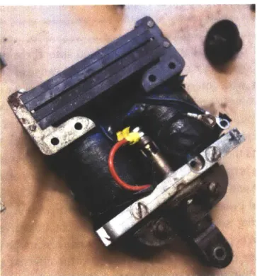
Figure 5: Picture of the Wico Model EK Magneto that was used in a Universal Fisherman one-lunger.
4 Material Castability and Pouring Temperatures
Castability of alloys is influenced by their shrinkage factors and freezing range. The freezing range corresponds to the liquidus and solidus temperatures on phase diagrams for specific alloys. Fluidity of an alloy is a measure of the distance to which a metal will flow before solidifying. Generally, high fluidity ensures good castability.
Table 1 shows the shrinkage allowance, approximate liquidus castability rating, and fluidity rating for various copper-base alloys.
temperature,
Table 1: Foundry properties of the principal copper alloys for sand casting [7].
Shrinkage Approximate liquidus temperature
UNS No. Common name allowance, % "C F Castability rating(a) Fluidity rating(a)
C83600 Leaded red brass 5.7 1010 1850 2 6
C84400 Leaded semired brass 2.0 980 1795 2 6
C84800 Leaded semired brass 1.4 955 1750 2 6
C85400 Leaded yellow brass 1.5-1.8 940 1725 4 3
C85800 Yellow brass 2.0 925 17(X) 4 3 C86300 Manganese bronze 2.3 920 1690 5 2 C86500 Manganese bronze 1.9 880 1615 4 2 C87200 Silicon bronze 1.8-2.0 .. ... 5 3 C87500 Silicon brass 1.9 915 1680 4 1 C90300 Tin bronze 1.5 1.8 980 1795 3 6 C92200 Leaded tin bronze 1.5 990 1810 3 6 C93700 High-lead tin bronze 2.0 930 1705 2 6
C94300 High-lead tin bronze 1.5 925 1700 6 7
C95300 Aluminum bronze 1.6 1045 1910 8 3 C95800 Aluminum bronze 1.6 1060 1940 8 3
C97600 Nickel-silver 2.0 1145 2090 8 7 C97800 Nickel-silver 1.6 1180 2160 8 7
(a) Relative rating for casting in sand molds. The alloys are ranked from I to 8 in both overall castability and fluidity; I is the highest or best
possible rating.
The copper-base casting alloy family is divided into three groups based on the freezing range. Alloys with narrow freezing ranges, a range of 50 'C, are represented in group I; alloys with intermediate freezing ranges, a range of 50 to 110'C, are represented in group II; and alloys with wide freezing ranges, well over 1100C, are
represented in group III. Table 2 lists the pouring temperatures for alloys of group I,
II, and III. The pouring temperatures are above the liquidus temperature for the
alloys. Table 3 lists the pouring temperatures for various classes of grey iron. When the freezing range is narrow, or the alloy is in group I, proper attention must be given to gate placement and riser design so that there is no irregular shrinkage in the cast or to prevent cold breaking. Alloys in group III, with wide freezing ranges, form a mushy zone during solidification, which results in interdendritic shrinkage or microshrinkage. When a metal is in the mushy zone of its phase diagram, proper feeding cannot take place and porosity results in the affected sections. Design and riser placement, plus the use of chills, are important in preventing these effects. Maintaining close temperature control of the metal during pouring and providing rapid solidification can also help prevent the pour from entering the mushy zone, but this method limits section thickness and pouring temperatures and also requires a more elaborate gating system that will ensure directional solidification [7]. Directional solidification ensures that solidification of the molten metal occurs in such a manner that liquid metal is always available to feed the portion of the cast that is solidifying. Directional solidification is always desired - it becomes more difficult to achieve the more complex the cast is.
Table 2: Pouring temperatures of copper alloys [7]. Alloy type Group I alloys Copper Chromium-copper Yellow brass Manganese bronze Aluminum bronze Nickel bronze White brass Group 11 alloys Beryllium-copper Silicon brass Silicon bronze Copper-nickel UNS No. C81 100 C81500 C85200 C85400 C85800 C87900 C86200 C86300 C86400 C86500 C86700 C86800 C95200 C95300 C95400 C95410 C95500 C95600 C95700 C95800 C97300 C97600 C97800 C99700 C99750 C81400 C82000 C82400 C82500 C82600 C82800 C87500 C87800 C87300 C87600 C87610 C96200 C96400 Light castinges C 1230-1290 1230-1260 1095-1150 1065-1150 1150-1175 1150-1175 1150-1175 1150-1175 1040-1120 1040-1120 1040-1095 1150-1175 1120-1205 1120-1205 1150-1230 1150-1230 1230-1290 1120-1205 1065-1150 1230-1290 1205-1225 1260-1425 1315-1425 1040-1095 1040-1095 1175-1220 1175-1230 1080-1120 1065-1120 1050-1095 995-1025 1040-1095 1040-1095 1095-1175 1095-1175 1095-1175 1315-1370 1370-1480 Heavy castings C F F 2250-2350 2250-2300 2000-2100 1950-2100 1950-2150 1950-2150 1950-2150 1950-2150 1900-2050 1900-2050 1900-2000 1950-2150 2050-2200 2050-2200 2100-2250 2100-2250 2250-2350 2050-2200 1950-2100 2250-2350 2200-2240 2300-2600 2400--2600 1900-2000 1900-2000 2150-2225 2150-2250 1975--2050 1950-2050 1925-2000 1825-1875 1900-2000 1900-2000 2000-2150 2000-2150 2000-2150 2400-2500 2500-2700 1150-1230 1205-1230 1010-1095 1010-1065 1010-1095 1010-1095 980-1065 980-1065 950-1040 950-1040 950-1040 980-1065 1095-1150 1095-1150 1095-1175 1095-1175 1175-1230 1095-1205 1010-1205 1175-1230 1095-1205 1205-1315 1260-1315 980-1040 980--1040 1220-1260 1120-1175 1040-1080 1010-1065 1010-1050 1025-1050 980-1040 980-1040 1010-1095 1010-1095 1010-1095 1230-1315 1290-1370 2100-2250 2200-2250 1850-2000 1850-1950 1850-2000 1850-2000 1800-1950 1800-1950 1750-1900 1750-1900 1750-1900 1800-1950 2000-2100 2000-2100 2000-2150 2000-2150 2150-2250 2000-2200 1850-2200 2150-2250 2000-2200 2250-2400 2300-2400 1800-1900 1800-1900 2225-2300 2050-2150 1900-1975 1850-1950 1850-1925 1875-1925 1800-1900 1800-1900 1850-2000 1850-2000 1850-2000 2250-2400 2350-2500 .4
Group HI alloys Leaded red brass
Leaded semired brass Tin bronze
Leaded tin bronze
High-leaded tin bronze
Table 3: Typical pouring temperatures for some classes
is minimal, about 1%.
of gray iron [7]. Shrinkage for grey cast iron
Pouring temperature Approximate liquidus temperatu
1150 1175 1200 1220 F 2100 2150 2190
re Thin sections Thick sections Thin sections Thick sections C F C F ~ C F I J, 1400 2550 1425 2600 1450 2640 1470 2680 1370 2500 1345 2450 1315 2400 1400 2550 1370 2500 1345 2450 1420 2590 1395 2540 1365 2490 1445 2630 1415 2580 1390 2530
5 Machinability and Material Selection
Machinability is defined as the ease with which materials can be machined. It generally decreases with increasing penetration hardness and yield strength and with increasing ductility. Machinability varies most between material classes or base chemistries, see the table below.
Table 4: Machinability for various classes of materials (in order of decreasing machinability) [7].
Machinability Magnesium alloys Aluminum alloys Copper alloys Gray irons Nodular irons Carbon steels Stainless steels
Hardened and high-alloy steels Titanium alloys C83450 C83600 C83800 C84400 C84800 C90300 C90500 C90700 C91 100 C91300 C92200 C92300 C92600 C92700 C92900 C93200 C93400 C93500 C93700 C93800 C94300 1175-1290 1150-1290 1150-1260 1150-1260 1150-1260 1150-1260 1150-1260 1040-1095 1040-1095 1040-1095 1150-1260 1150-1260 1150-1260 1175-1260 1095-1205 1095-1230 1095-1230 1095-1205 1095-1230 1095-1230 1095-1205 2150-2350 2100-2350 2100-2300 2100-2300 2100-2300 2100-2300 2100-2300 1900-2000 1900-2000 1900-2000 2100-2300 2100-2300 2100-2300 2150-2300 2000-2200 2000-2250 2000-2250 2000-2200 2000-2250 2000-2250 2000-2200 1095-1175 1065-1175 1065-1175 1065-1175 1065-1175 1040-1150 1040-1150 980-1040 980-1040 980-1040 1040-1175 1040-1150 1050-1150 1065-1175 1040-1095 1040-1121 1010-1150 1040-1150 1010-1150 1040-1150 1010-1095 2000-2150 1950-2150 1950-2150 1950-2150 1950-2150 1900-2 100 1900-2100 1800-1900 1800-1900 1800-1900 1900-2150 1900-2100 1920-2100 1950-2150 1900-2000 1900-2050 1850-2100 1900-2100 1850-2100 1900-21W 1850-2000 C(Iass 30 35 40 45
Small castings Large castings
Most material classes include "free machining" alloys. Free machining materials are
100% machinable materials that do not deteriorate tools or have good chip formation
characteristics. The more homogeneous and the finer the grain structures of the material, the easier it is to machine. Alloy additives can also be used to increase machinability but these may compromise material properties that are necessary for certain applications, such as hardness or strength. Some examples of alloy additives include "lead in brasses and steels, sulfur compounds in steels and powder metals, and insoluble metals such as bismuth, selenium, and tellurium in steels" [7].
There are wrought alloys and casting alloys. Wrought alloys are heated and worked after casting, while cast alloys simply just exist as they are cast. Wrought copper alloys optimize strength, ductility (formability), and thermal stability, without inducing unacceptable loss in fabricability, electrical/thermal conductivity, or corrosion resistance. Copper casting alloys offer their own unique composition and property characteristics and are used for their high-thermal and electrical conductivity [7]. Table 1 shows the compositions of wrought and cast copper-base alloys. Wrought iron is a commercial iron that consists of slag (iron silicate) fibers that are entrained in a ferrite matrix. Cast iron consists of more carbon than wrought iron and is very brittle and will fracture before it bends, unlike wrought iron which is malleable. Grey iron is used for many of the cast parts in the Atlantic engine, such as the cylinder and the piston. It is cheap, strong, and still easily machined when not quenched. Iron has good thermal properties, such as a high coefficient of thermal expansion, which make it a good choice of material for parts that withstand a fair amount of heat. As the material heats up, it is less likely to expand than a part made of an aluminum alloy, thus tolerances can be tighter. Iron also maintains strength at higher temperatures, allowing for thinner geometries and the wear strength of iron is also high. Iron should be poured at a temperature of around 1400 OC. Nowadays, advances in aluminum alloys gave way to aluminum pistons because there are advantages in weight and thermal conductivity - a lighter piston requires less inertia to run and therefore can be more efficient, and high thermal conductivity produces pistons that experience little variation in temperature when in use. The table below describes the main engine parts or systems and their material and method of manufacture.
Table 5: Generic classification of copper alloys [7].
Generk name UNSN. Compasion
Wrought alloys
Coppers CIOIOG-C15760 >99% Cu
High-copper alloys C16200-C19600 >%% Cu
Brasses C20500-C28580 Cu-Zn
Leaded brasses C31200-38590 Cu-Zn-Pb
Tin brasses C40400-C49080 Cu-Zn-Sn-Pb
Phosphor bronzes C50100-C52400 Cu-Sn-P
Leaded phosphor bronzes C532005-C4800 Cu-Sn-Pb-P
Copper-phosphorus and copper-silver-phosphoms alloys C55180-C55284 Cu-P-Ag
Aluminum bronzes C60600-C64400 Cu-Al-Ni-Fe-Si-Sn
Silicon bronzes C64700-C66100 Cu- i-Sn
Other copper-zinc alloys C66400-C69900 ...
Copper-nickels C70000-C79900 Cu-Ni-Fe
Nickel silvers C73200-C79900 Cu-Ni-Zn
Cast alloys
Coppers C80100-C 81100 >99% Cu
High-copper alloys C81300-C82800 >94% Cu
Red and leaded red brasses C83300-C85800 Cu-Zn-Sn-Pb (75-89% Cu) Yellow and leaded yellow brasses C85200-C85800 Cu-Zn-Sn-Pb (57-74% Cu) Manganese bronzes and leaded manganmse bronzes C86100-C86800 Cu-Zn-Mn-e-Pb
Silicon bronzes, silicon brasses C87300-C87900 Cu-Zn-Si
Tin bronzes and leaded 6in bronzes C90200-C94500 Cu-Sn-Zn-Pb
Nickel-tin bronzes C94700-C94900 Cu-Ni-Sn-Zn-Pb
Aluminum bronzes C95200-C95810 Cu-Al-Fe-Ni
Copper-nickels C96200-C96800 Cu-Ni-Fe
Nickel silvers C97300-C97800 Cu-Ni-Zn-Pb-Sn
Leaded coppers C98200-<98800 Cu-Pb
Special alloys C99300-C99750
Table 6: Atlantic engine material and manufacturing method breakdown by part or system.
Name of Part Material Method of Manufacture
Cylinder/Base Piston Piston Rings Iron Iron Iron, Steel Cast Cast Machine Cold rolled steel
Iron Cast, Forge Cast Connecting Rod Crankshaft Ignition System Bronze 936 Steel
Iron, Hardened Steel
Cast Machine Cast, Machine, Forge Piston Pin
Cooling System Bronze Bearings Flywheel Cast Cast Iron
6 Basic Foundry and Casting Terms
Flask Cope Drag Core Print Pattern Parting Line Sprue Runner Gate Draft Shrinkage
The metal or wooden box that holds the sand. There is a lip around the rim on both sides of both halves that helps keep the sand in place. Top half of flask.
Bottom half of flask.
A mold of the negative space of a part that allows for the creation of
cavities or hollow parts. If possible, core prints are made hollow to allow the print to vent properly.
The wooden, plastic, metal, or foam shape that creates the cavity of the sand mold within the flask. The pattern also includes the runner(s). The dividing plane of the part that separates the mold into the cope and drag. In some cases the parting line may not be a plane.
The channel that delivers metal to the runner or part. Usually cylindrical or hexagonal, about to 1 inch in diameter. A cup is usually cut out at the top of the sprue to facilitate easy pouring of the metal. The channel that delivers metal from the sprue to the part(s). Runners can be used to connect a casting of multiple parts. Runners can be part of the pattern (which are drafted semicircular or drafted rectangles in cross-section) or cut into the sand before pouring.
The location where metal enters the mold for the part. Runners/sprues will be cut from the part at this location.
The tapered edges of a pattern that allow for easy removal from the sand. Any surface or edge that would be perpendicular to the parting surface must have draft of 1 or 2 degrees. Remember to include draft on circular parts - anything that is normal to the parting surface is at risk for shearing which has the potential to destroy the sand mold. The reduction in volume as the metal cools, which is a leader factor in casting failures. Shrinkage can distort the cast beyond specified
tolerances or even break the cast all together. A scaling factor must be used on the pattern to ensure the shrunk part is the correct size. See table 1.
Cold A.k.a. hot cracking. Casting defect that occurs as a cast cools. Shrinking
Breaking metal pulls from a still molten area of the cast. If a section is cooling and it tries to pull molten metal from an already frozen section, it can break the part. More common for metals with large shrinkage factors like aluminum, but good patterns account for this.
Riser An added section to a pattern that fills with molten metal that acts as a reservoir for metal as it cools. Helps debug cold breaking.
Vent A channel for air. Can be used to get rid of trapped bubbles or vent out
inside of a core print.
Green Sand Most commonly used sand that is reusable and composed of sand,
clay, carbons, and water.
No-Bake Sand molds that don't require heat to cure.
Sand
Melting Temperature at which metal becomes molten. Varies for different
Point metals. See table 1.
Pouring Temperature at which metal is poured. Hotter than melting point. See
Temp. table 2 and 3.
7 Types of Casting Sand
Green sand is the most common type of casting sand. However, under different circumstances, other types of sand may be used in order to create a better cast. Moreover, cores and more complex casts can be made out of harder sand such as C02 sand or resin sand; these sands are known as "no-bake" sands as they do not require heat to cure.
7.1 Green Sand
Green sand is the fastest and least expensive of all the molding methods currently in use today. It is a mixture of sand, clay, carbonaceous materials, and water. Although sand casting creates expendable molds, used green sand is almost fully reusable after being rehydrated. Green sand is most commonly composed of washed silica sands. Clays used in green sand are usually bentonite, a.k.a. montmorillonite, or kaolinite, a.k.a. fireclay, clays. There are two types of bentonite clays: western, or sodium, and southern, or calcium. Western and southern bentonite clays differ in chemical composition and physical behavior. Bentonites are forms of hydrated aluminum
silicate. The structure and nature of the molecules creates clay particles that are flat and allow for the absorption of water - from which the clay expands - between clay plates. The major function of the clay in the green sand is that of a bonding agent by creating clay-water bonds. Bentonites are electrically neutral, thus the water molecules between clay plates and the water molecules absorbed in the sand create a network of adhesive attraction between clay and sand. There is an ideal amount of water, temper water, which bonds all of the clay and sand; it's called the temper point. At the temper point, the sand is at its maximum strength; below this point the sand is not fully bonded, and above this point some water will be in liquid form and not partake in the network of attraction between sand and clay. Figure 6 depicts the corresponding strengths of green sand and percentages of temper water used [8].
220 32 C E C 195 - __ -~-- __ 65 - --- - -- - - . 140 12 10% clay 110 85 ____ 28 24 0. 20 G 16 CL 12 E 4 0.5 1.0 1.5 2.0 2.5 30 35 4.0 4,5 5,0 5.5 60 6.5 70 Tempering water, %
Figure 6: Varying strength of green sand mixed with various percentages of southern bentonite and
water. Peaks indicate the temper point. [8]
The carbonaceous materials serve other purposes than bonding the sand. They can reduce penetration and burn-in, control expansion of the sand, improve dimensional stability of the mold (seacoal only), improve surface finish, and improve the cleanability of the finished casting [8].
Green sand can be optimized for a specific metals and surface finish by choosing the best type or mixture of sand, clay, and carbons and hydrating the sand properly. The composition of green sand used in this application is shown below:
1
I
100 lbs sand (olivine sand afs 100)
6 lbs southern bentonite
2 lbs western bentonite
3.5 lbs of water
7.2 Resin Sand
Resin sands are used for shell molding and coremaking. Compared to green sand, resin sand shell molds produce castings with greater dimensional accuracy and smoother surfaces. This type of sand can also be used to cast more complex parts. [8] The resin that was used for the Atlantic engine castings was Kenset R binder. Specifications of Kenset R are detailed in table 7. A TSA, tungstate sulfuric acid, catalyst initiates and speeds the reaction of the binder [9]. The formula for the resin sand used was as follows:
Sand
Binder...2% wt. sand Catalyst...1% wt. sand
The binder must be mixed in first because once the catalyst comes into contact with the binder, the sand starts to cure and even coating of binder on sand grains is necessary. This resin sand was a "no-bake" sand, meaning no heat was required to cure the molds. The amount of catalyst can be adjusted to either shorten or elongate the curing time. The more catalyst added, the faster the reaction occurs, and the faster the sand cures. The sand is cured when it is a dark, black color. Table 8 compares the advantages and disadvantages of resin sand.
Table 7: Specifications of Kenset R, the resin used in the no-bake sand [9].
Specification Kenset R Ph 6.0 - 7.0 Viscosity > 60 cps Nitrogen 6.5 % Water 6.5% Free Formaldehyde 10 - 12.5 %
Wt. Per Gallon
Color Opaque Orange
Table 8: Advantages and disadvantages of resin sand.
Advantages Disadvantages
Greater dimensional accuracy Shrinkage
Smoother surfaces High cost of resin
Less sand required Toxic substances
Fewer restrictions on casting design Short working period
8 Prepping Part CAD and Model for Casting
8.1 Before prepping your CAD model for casting: 1 Decide on parting line. Will it be a plane or irregular?
2 If there is a core, choose a parting line for the core. The parting line for the core does not have to be the same as the regular parting line.
3 Decide which half of the part will be placed in the cope and drag. Remember, you
want to fill your part with metal from the bottom up, meaning ideally, more of the part should exist within the cope.
4 Confirm that there is a flask large enough for your part, if not, make one. Wood glue and nails has been proven to be strong enough for a 13" cube flask. Also create a lip around the rim of the box. The lip helps keep the sand in place when the flask is being flipped over and moved.
5 Decide where the gate will be. The gate should be placed in a location that will
create the least turbulence during the pour and also allow for the shortest possible length of metal flow.
6 Save a copy of the final, machined part - you will be creating many more files during the cast prep and you do not want to overwrite the machined part.
8.2 Prepping the CAD model for casting:
1 Add a scaling factor that accounts for shrinkage. Shrinkage factor varies by
material. See table 1.
2 Delete small through holes and other machined features. Shrink holes that will be cast to allow for post-machining.
3 Add material for facing off or turning down. " is usually enough. Save file as "cast model."
4 Save as new copy (copies if core is asymmetrical) and open. Save file as "core." Split part at the core's parting line, which may differ from the patterns parting line. If the core is asymmetrical, complete the steps below on the files of both core halves. If core is symmetrical, create the mirror half of the core mold as a last step.
5 Add draft and fillets for the inside of the part only.
6 Create the core by adding a new solid body that shares a face with the part's parting line surface. Subtract the part from the solid body. The core should remain.
7 Add an alignment feature to the core.
8 Make sure the alignment feature is drafted in the proper direction. You should now have two asymmetrical halves of a core with an alignment feature or one half of a symmetrical core.
9 Save as new copy and open. Save as "core mold." Create the core mold -add a new solid body that shares a face with the core's parting line. Subtract the core from new solid body. Make sure that at least one section of the mold is left open to allow space to press in the sand. The outward facing surface(s) of the alignment feature(s) is the ideal choice.
10 Add pins and/or holes to align the mold halves.
11 Open "cast model." Split the cast model in half (save as two files if part is
asymmetrical) on the parting line, which may differ from the parting line of the core.
12 Save as copy and open. Name "cast model without core" and delete the core.
13 Create new file and combine "core" with the casting model "cast model without
core" - this is the pattern you will cast. Save as "pattern." Note: It may be necessary to add extra material in places where the core and the cast model meet if the draft is not in the same direction. Use your discretion and check the full model carefully for awkward gaps. Using the Solidworks Move/Copy Body feature, properly mate the "cast model without core" and the "core." Look back at the "cast model" to ensure that the measurements are correct.
14 Add cylindrical indents to both halves of the pattern to allow for correct alignment across the parting board or surface. If 3D printing the pattern, make it thin walled or hollow so there is less to print.
15 Manufacture the "pattern" and the "core mold."
16 There will be two halves of the pattern and two halves of the core mold. Under
other circumstances only one half of the flask can be used if there is no parting line.
Note: For parts with no core omit all steps involving the core.
8.3 Creating the Pattern
The pattern can be manufactured using multiple methods. Traditionally, patterns were made of wood, but advances in technology have made other methods available.
3D printing patterns and molds is the least labor intensive method. After parts have
been printed, an acetone bath is advised in order to smooth the surface and allow for the pattern's easy removal from the sand. In order to properly conduct an acetone bath place the part on an aluminum sheet in an air tight container and surround the part with acetone soaked paper towels. Do not let the paper towels touch the 3D printed parts because contact with liquid acetone will melt the pattern. Leave the parts in the bath for about one and a half hours and the surface finish should be smooth and 3D print lines are no longer visible. Patterns can also be made on a wood lathe and with other wood tools and pieced together.
9 Casting the Part: Basic Green Sand Casting
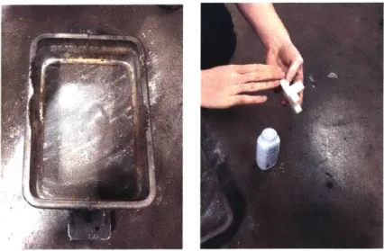
The first part to be cast for the engine was the igniter body. It was a fairly simple part, having no core. The basic steps of casting with green sand are detailed below, using the igniter body as an example, which does not have a core.
Step One Powder the parting board and the patterns. Talc powder (baby
powder) is used. Note that the floor may be used as the parting surface. Place the cope, topside down, on the parting surface.
Figure 7: Cope is placed on the floor, top side down. The floor and pattern are powdered.
Step Two Place the part(s) on the parting surface.
Figure 8: Top half of part is placed on the parting surface.
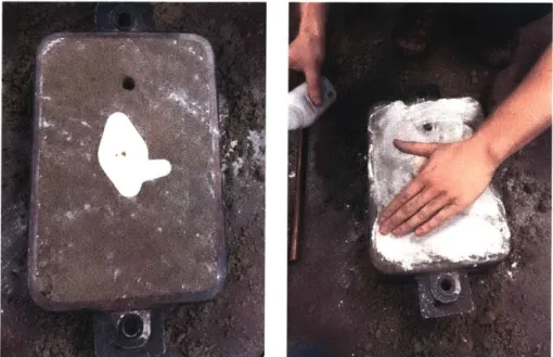
Step Three Place a dowel and hold upright in place to serve as a sprue. Choose the sprue location carefully. The sprue can also be cut in afterwards using a hollow metal tube.
Step Four Add a layer of sand, enough to cover most of the part. Press the sand
Figure 9: A dowel is placed to form the sprue and the cope is filled and rammed with sand in layers.
Step Five Continue adding layers of sand and packing down the sand. The sand should not comply when pressed. The better the packed sand, the better the cast part. Using a rod or other straight surface, scrape off excess sand. Cut out a cup around the sprue.
F'
I:
Figure 11: Cope is flipped over and powdered with talc.
Step Six Remove the dowel. Flip the cope over. The parting surface of the first
half of the part is now visible. Powder the surface with talc.
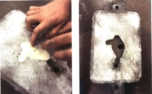
Step Seven Place the bottom half of the part on the parting surface, using the aligning features. Place the drag on top of the cope with the parting surface side down and clamp the flask together.
Step Eight Pack sand into the drag as was done in the cope.
Step Nine Unclamp the flask and remove both halves of the model. If a core is involved, place the core in the mold according to the aligning features. Reclamp the flask and pour the metal.
Figure 13: The part is removed from the sand with the help of a tapped screw.
Figure 14: Cope is placed on top of drag and clamped prior to pouring.
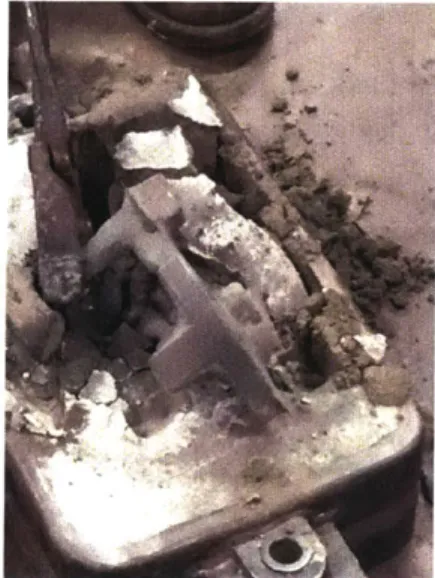
Step Ten Let the cast cool. Quenching after casting is not advised for parts that
are post-machined. For large parts, cooling takes place overnight. After the cast has cooled, break it out of the mold and begin machining or evaluate what failed and iterate on the mold design.
Figure 15: After metal has been poured and the part has cooled it is removed from the sand.
10 Casting the Part: Advanced - Shell Casting the Piston
I
The piston is a complicated cast. The cylinder beats the piston in terms of volume, complexity, and number of cores, so learning to cast the piston correctly is vital to the understanding and success of the cylinder cast. The first attempt to create the piston was a failure, and as was the second and third. The piston was to be cast without a parting line, placing the sprue directly on the center of the top surface. The pattern and core mold for the piston were 3D printed. Each was split in half and each half took two days to print. The two halves of the piston pattern were then epoxied together and clamped overnight. The core mold had alignment pins on both halves that allowed the mold to be put together easily and accurately, and also helped the halves from bursting open when being packed with sand.
I
Figure 17: Mold for piston core (left) and piston pattern (right).
10.1 First Attempt
First, a flask was created to accommodate the size of the piston and a lip was used in order to help keep the sand in the flask. The flask was a 13" cube, designed to leave at least two inches of sand between the pattern and the flask in any given spot. The flask was made of " plywood and did not need any reinforcements, but handles were added to make carrying the flask easier. For larger flasks, reinforcements may be needed in order to keep the sides of the flask from bowing out because the movement of sand in the flask would ruin the cast.
Figure 18: Core print made of resin sand, first attempt.
The core print was originally attempted using C02 sand, but it was not strong enough and easily broke. The decision was made to use no bake resin sand that solidifies much harder than C02 sand. The resin sand was created in 2 kg batches and the use of a kitchen aid mixer. For each batch of sand, the resin and catalyst consists of 3% of the weight of sand - in this case 60 grams. The formula calls for 2/3rds resin, which is mixed in first, and 1/3 catalyst, which gives 40g of resin and 20g of catalyst. Less catalyst can be used in order to slow the curing time of the sand. There were about
7-10 minutes of working time after the catalyst was mixed in and separate batches of
sand don't necessarily bind together if too much time separates them. Remember that with resin sand, time is always against you. The resin sand was patted down on the inside of the core mold as to leave the core print hollow to allow for venting. After letting the core print cure, the mold was opened - however the core broke at the interface with the aligning feature, which made it impossible to cantilever the core into the flask and thus more difficult to align the core print properly. It is possible the core print broke because no powder was applied prior to filling it with sand - this is a very important step and must not ever be overlooked.
While the core print cured, the flask was prepared. A 13" cube takes quite a bit of time to fill and ram with sand. Green sand was used and put down in layers and rammed until the flask was full. The sprue was then cut in using a copper tube.
Figure 19: The piston pattern in placed in the flask and the flask is filled and rammed with sand.
A vent was then cut in that connected the center of the core print to the top surface of
the flask. A base flask (about 13"x13"x5") was also prepared with green sand and the core print was placed on the center of it. The pattern was removed from the main flask and was carefully lowered onto the base flask, making sure that the core properly aligned with the alignment feature on the flask - this was difficult because the flask was very heavy, and it was difficult to see and align the core print while simultaneously lowering the heavy flask. That is why the core was designed to be cantilevered into the flask.
Figure 20: Molten iron is poured into the flask and flames appear from the top. The cast did not appear to fill fully.
Now that the flask was fully prepared, iron was melted and poured into the mold. It was instantly known that the cast failed as all of the iron was consumed. The core was not strong enough and imploded, leaving behind a lump of iron on the base flask.
vi 4
7t A
I
10.2 Second Attempt
Figure 22: Second attempt at creating the core print. The mold is filled fully with sand using a copper
tube to create a vent in the middle.
Given that the core imploded during the first attempt, the core was filled solid with resin sand using a copper tube to create a vent in its center. The aligning feature now had substantial support, enough to hold up the core print to the weight of the iron being poured. The copper tube was removed once the mold was filled and packed. Since the mold was again not powdered, the core print broke at the interface of the aligning feature and glued back together.
A
Figure 23: Pattern of the piston. The seams were plastered and sanded to make it easier to remove the pattern from the sand.
The pattern for the piston was also cleaned before the second attempt. Plaster was applied and sanded at the seams in order to make the pattern smoother and easier to remove from the flask. Resin sand was applied to the outside of the pattern, after coating it with powder, in an attempt to complete a shell casting of the piston. However, the vertical nature of the piston and the fact that the resin sand begins to cure quickly made it impossible to create a full shell of the pattern. Once the catalyst was added to the resin sand, it needed to be thoroughly mixed to ensure proper bonding. When the sand turned a light, moss, green it was ready to be packed, but once it reached a dark green it became less workable and would not bond to new resin sand, and there were only a few minutes in between shades depending on how much catalyst was added. So in the end, instead of a full shell cast, a shell of the aligning feature was created - which was all that was really necessary. It makes it easier to
align the core properly and also keeps the green sand from being bumped and destroyed when inserting the core, since the resin sand shell is much more bonded and hard than the green sand.
I
Figure 24: Attempt at creating a shell mold for the pattern. The resin sand cured too quickly and was difficult to secure to the vertical sides of the pattern.
Figure 25: The shell broke apart only leaving the part surrounding the aligning feature intact.
The pattern with the resin sand shell still attached was then packed with green sand in the flask, just like first attempt. The main and base flask were packed and the pattern was removed. The core print was vented through the base flask, unlike the first attempt. Since the core print was broken, the main flask was again lowered on to the base. Iron was melted and poured, but again, the cast appeared to not be fully
filled.
Figure 26: Left -the cope after the pattern was removed, leaving behind the cavity that would create the piston. Center -the flask is lowered onto the base flask and the core print is aligned. Right - the
resulting cast piston. It did not fill with metal fully.
!t
._Iq
now,;
There was not enough metal poured to compensate for the flash, the sprue, and the spillage! The core did work well however, and the surface finish was good. The surface finish on the outside of the piston was poor, but it was not critical since the piston would turned down.
W
Figure 27: Cavity of the second
10.3 Third Attempt
attempted piston. The surface finish is good aside from some flash and disturbances near the bosses.
Figure 28: A small box was created in order to attempt a full shell casting of the piston. The pattern
is placed in the box and filled with resin sand.
iL
VII
J
A full shell casting was attempted by creating a small box to fill with resin sand, since
patting down sand onto the pattern was unsuccessful. A full shell cast of the piston would create a better surface finish on the outside. However, the full shell was unsuccessful. The resin sand shrinks as it cures; if it surrounds a pattern, it will be almost impossible to remove the pattern from the shell. Even after excessive hammering on the copper tube that created the sprue, the pattern would not budge.
The box was dismantled and more hammering commenced with no luck. A small hole on the top edge of the pattern was created and hammered and still the pattern would not release. The decision was made to cut half of the top shell off in order to hammer the pattern out more easily, but the entire top layer of the shell broke off. This finally released the pattern, but it was also broken. The moustache shaped feature on the piston was stuck in the resin sand.
Figure 29: The moustache feature was stuck in the resin sand and broke off when the pattern was being removed from the shell.
Since the pattern was broken, it needed to be fixed before another pour could occur. The moustache was salvaged and re-epoxied to the pattern. Plaster was then added to smooth out the interface between the moustache and the top surface, and dents that were created during hammering were filled in. The top of the pattern was sanded down until smooth, and the pattern was ready to be cast once again.
m0
Figure 30: The moustache feature of the piston was epoxied to the pattern. The top was then
plastered to fill in any holes and sanded to smooth out the surface.
Upon returning to the shell mold, more cracks had developed and the shell split at the layers. Since the shell mold was still extremely tight on the pattern, the top two layers that broke off were not glued back together to the rest of the shell and this eased some of the friction that was keeping the pattern stuck. In the end, the shell only covered the aligning feature.
I
* %~w >~&~
1(4
Figure 31: The shell casting of the piston fell apart at the boundary between resin sand layers. The
first two layers were salvaged and only covered the alignment feature of the pattern.
0
Like during the other attempts, the core print was created using the resin sand. Powder was coating the mold and the print released whole - the first perfect core. This was ideal because the core could then be cantilevered into the flask.
Figure 32: The core print was cantilevered into the flask and then the flask was moved onto the base and iron was poured.
Twenty-four pounds of iron were melted to ensure that there would be a sufficient amount, and there was plenty left over. A full cast of the piston was created. There was an air bubble on the side of the piston, but it was in the vicinity of the piston rings -- the bubble should not hurt the efficiency of the piston since the compression rings should seal around the length of the piston. See
below for more pictures of the cast piston. Most important things learned:
* Resin sand has a short period of workability
7
Resin sand shrinks
e Separate resin sand layers usually do not bind well
T Resin sand creates a much better surface finish than green sand
s Cores must be hollow and vented but sturdy
"
Coating patterns with talc powder is a vital step towards a successful cast" Proper draft is critical and all angles should be filleted if possible
V4
Figure 34: Full cast of the piston (left) and the cavity (right). The finish of the piston cavity is excellent.
Figure 35: A void appeared on the piston. It is located in the vicinity of the piston rings so it should be mostly bored out and should not affect the piston performance.
Figure 36: The difference in surface finish can be seen. The left side is where green sand met the pattern, the right side is where resin sand met the pattern.
j
r
11 Curriculum Suggestions
A suggested timeline for a 2-stroke engine fabrication is below. In addition to
managing time properly and efficiently, various lectures should be held at the beginning of the term. Lectures start the work week. First, students must learn about the combustion engine cycle and the purpose of each subsystem. A demo casting is suggested early in the term to allow for easier understanding of the casting methods, pattern preparation, and terminology, topics which should be taught in conjunction with the demo and reiterated and elaborated on in the lecture following the demo. Students must learn about and be able to identify the foundry tools and casting features that aid the casting process. These include the flask (cope and drag), the crucible, the furnace, personal protective equipment, sand types, draft, sprues, gates, risers, vents, etc. The more the student knows before designing the pattern, the better, and in order to obtain a comprehensive understanding of sand casting methods, metallurgy should also be taught. The more the students learn about the metal and its behavior from its liquid to solid state, the more informed the student will be to make casting decisions and pattern design.
Table 9: Suggested schedule.
Weeks Lectures Work
Engines: two-stroke versus four-stroke, ignition methods, important part
identification / function / vital features.
1 Divide up workload: ignition (2), flywheel Engine CAD
(1), base (2), cylinder (2), piston (1),
connecting rod (1), water pump (1), eccentric (1)
Demo casting: what makes a good mold, Engine CAD
2 2 good casting practices End of week: CADEdo ek A
assembly, buy materials Familiarize with casting Casting do's and don'ts: draft, overhang, gate terminology
3 location, parting line choice, orientation, Pattern CAD
sand types Machining Prep/ Start
machining
4 Metallurgy, phase diagrams, pouring Pattern CAD
/
Machining temperaturesPattern Fabrication / 5 Pattern CAD check and review. prepare patterns for
casting 6
7 8 9
10 Work Period (9 weeks): Casting, Machining
11
12
13
14
is Finishing touches on parts/ Assembly (run piston through cylinder via an external source for a few days)
16 Assembly/ official running
Table 10: Allotted pattern making, casting, and machining time during work period of 9 weeks:
Part Weeks to Weeks to Weeks to
complete pattern complete cast complete
or prep for machining /
machining assembly
Piston 2 4 3
Cylinder 4 2 (out of house) 3
Crankshaft 3 N/A 6
Flywheel 4 2 (out of house) 3
Base 4 2 (out of house) 2
Ignition 1 2 6
Water Pump 1 2 6
Eccentric 1 2 6
The schedules provided are a suggestion and will be difficult to keep up with. Casting is a fickle process for beginners, which is why emphasis on the theory of casting is necessary. The more the student knows about casting prior to completing their first pour, the more likely the pour will be successful.
12 Conclusion
Casting is an intense process that takes years to master. This thesis aims to help those completing their first casts. The knowledge from this paper aims to assist in the creation of another combustion or steam engine. Time management and collaboration is key, not only between students, but also departments, lab directors, and foundries.
Acknowledgments
The author would like to thank Daniel Braunstein and the Pappalardo staff for being extremely supportive of this project. Thank you to Mike Tarkarian, head of the Materials Science Foundry, for joining us on this venture.
References
[1] Grayson, Stan. "Old marine engines: The World of One Lunger."
[2] Monchy, Marike Finlay-de and Cope, Karin. "Casting a Legend: The Story of the Lunenburg Foundry." 2002.
[3] Imgur. http://i.imgur.com/o5oKsfh.gif
[4] Matthews, Harry. 2007. "Ignitions." www.old-engine.com/maglco.htm
[5] GEM Staff. 1978. "Wico Magneto Cycle of Operation (Type EK)." Gas Engine
Magazine. http://www.gasenginemagazine.com/equipment/wico-magneto-cycle-of-operation-type-ek.aspx
[6] Wotry, Bud, 1977. "The Remarkable Wico Model EK Magneto." Gas Engine
Magazine. Big Rapids, Michigan.
[7] Davis, J.R.. (1998). Metals Handbook, Desk Edition (2nd Edition). ASM
International. Online version available at:
https://app.knovel.com/web/toc.v/cid:kpMH DE E004/viewerType:toc/root-slug:m etals-handbook-desk/url-slug:kto10QTQMM
[8] ASM International Handbook Committee. (2008; 2010). ASM Handbook, Volume 15 -Casting. ASM International. Online version available at:
http://app.knovel.com/hotlink/toc/id:kpASMHVC04/asm-handbook-volume-15/asm-handbook-volume-15
[9] Malcom G. Stevens, Inc. "Binders, Core Oil, Flux & Degassers."


![Table 7: Specifications of Kenset R, the resin used in the no-bake sand [9].](https://thumb-eu.123doks.com/thumbv2/123doknet/14204699.480663/19.918.274.606.786.1092/table-specifications-kenset-r-resin-used-bake-sand.webp)