Building Model
Generating a ModelGeneration
of the MIT Campus
Project:
TerrainVitaliy
by
Y. Kulikov
Submitted to the Department of Electrical Engineering and Computer Science in Partial Fulfillment of the Requirements for the Degree of
Master of Engineering in Electrical Engineering and Computer Science at the MASSACHUSETTS INSTITUTE OF TECHNOLOGY
May 20, 2004
Copyright 2004 Massachusetts Institute of Technology. All rights reserved.
Author _
Department of Electrical Engineering and Computer Science May 20, 2004 Certified by Seth Teller Thesis Supervisor Accepted by Arthur C. Smith Chairman, Department Committee on Graduate Theses
MASSACHUSETTS NTITUTE OF TECHNOLOGY
Building Model Generation Project:
Generating a Model of the MIT Campus Terrain by
Vitaliy Y. Kulikov
Submitted to the
Department of Electrical Engineering and Computer Science May 20, 2004
In Partial Fulfillment of the Requirements for the Degree of Master of Engineering in Electrical Engineering and Computer Science
Abstract
Possession of a complete, automatically generated and frequently updated model of the MIT campus leads the way to many valuable applications, ranging from three-dimensional navigation to virtual tours. In this thesis, we present a set of application tools for generating a properly labeled, well-structured three-dimensional model of the MIT campus terrain from a set of geographical and topographical plans. In particular, we present the Basemap Generator application capable of generating a two-dimensional model of the MIT campus by subdividing the contour map of the campus into a set of distinguishable spaces labeled with specific label types (including but not limited to grass, sidewalk, road, ramp) as necessary. We also present the Basemap Modeler application capable of transforming the two-dimensional model of the campus into 3D. Finally, we provide two auxiliary applications, the Basemap Examiner and the Building Mapper, capable of minimizing negative effects due to erroneous input data. Thesis Supervisor: Seth Teller
Acknowledgements
I would like to express my gratitude to many people around the world for making this project possible.
I would like to thank my parents for their constant support and for sharing with me all their passion for science and technology. It is to them that I dedicate this thesis.
I would also like to thank Seth Teller, my UROP and MEng advisor, for his assistance, ideas, and enthusiasm, without which the BMG project at MIT would not be possible.
I also owe special thanks to my colleagues in the Computer Graphics Group for their support and assistance, including Bryt Bradley, Michael Craig, Adel Hanna, Peter Luka, and Patrick Nichols.
Last, but in no way least, I would like to thank Catarina Bjelkengren, whose wonderful personality, thoughts, and ideas inspired me throughout the project.
Contents
Chapter 1 11Introduction
Chapter 2 15Design
2.1 Basemap Generator 17 2.2 Basemap Examiner 31 2.3 Basemap Modeler 33 Chapter 3 35Implementation
3.1 Common Library 37 3.2 FLParser Library 42 3.3 Graphics Library 45 3.4 Geometry Library 54 3.5 Basemap Generator 57 3.6 Basemap Examiner 64 3.7 Basemap Modeler 69 Chapter 4 73Future Work and Conclusions
4.1 Adding New Space Label Types 73
4.2 Detecting Erroneous T-junctions 74
4.3 Filtering Out Invalid Z-coordinates 75
Appendix A 77
Project Build Instructions
A.1 Checkout and Build Instructions 77
A.2 Invoking Applications 78
A.2.1 Basemap Generator 79
A.2.2 Basemap Examiner 81
A.2.3 Basemap Modeler 83
A.2.4 Building Mapper 84
Appendix B 87
File Formats
B.1 .SPACES File Format 87
B.2 .PORTALS File Format 88
B.3 .IT File Format 89
B.4 .TOPO File Format 90
B.5 .CNTR File Format 91
B.6 .TRNSF File Format 92
B.7 .CONTOURS File Format 93
B.8 .POINTS File Format 93
Appendix C 94
List of Figures
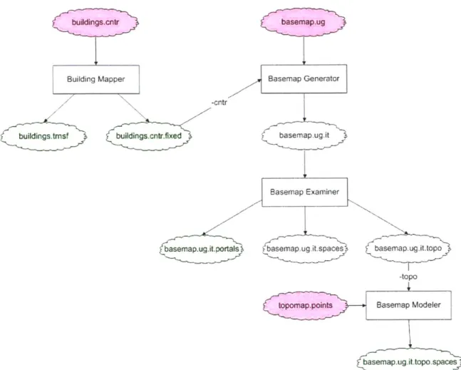
2-1 Data Flow Diagram of the Basemap Generator 16 Project
2-2 Basemap Generator Application in the Debugging 19 Mode: TRIANGULATOR process
2-3 Examples of the Erroneous Contours 21 2-4 Basemap Generator Application in the Debugging 22
Mode: PATCHBUILDER process
2-5 Basemap Generator Application in the Debugging 24 Mode: PROBASSIGNER process
2-6 Basemap Generator Application in the Debugging 26 Mode: TYPEASSIGNER process
2-7 Part of the Basemap Corrected Using the Basemap 28 Examiner Tool
2-8 Building Mapper Snapshot 30
2-9 Basemap Examiner in the Debugging Mode 32 2-10 3D Model of the MIT Campus Terrain as Viewed 34
from the ivview Application Window
3-1 Overall Structure of the Basemap Generation 36 System
3-2 Modular Dependency Diagram of the Common 38 Library
3-3 Modular Dependency Diagram of the FLParser 44 Library
3-4 Modular Dependency Diagram of the Geometry 46 Library
3-5 Modular Dependency Diagram of the Graphics 55 Library
3-6 Modular Dependency Diagram of the Basemap 58 Generator Application
3-7 Modular Dependency Diagram of the Basemap 65 Examiner Application
3-8 Modular Dependency Diagram of the Basemap 71 Modeler Application
4-1 The MIT Campus Terrain Extruded into 3D Using 75 Partially Incorrect Topographical Data
Chapter 1
Introduction
The main goal of the Building Model Generator (BMG) research project at the MIT Computer Graphics Group is to develop a system capable of automatic extraction of an accurate three-dimensional model of the MIT campus from a set of two-dimensional architectural plans maintained by the Department of Facilities (DOF) at MIT [1]. Possession of a complete, frequently updated model of the campus would lead the way to many valuable applications, ranging from the three-dimensional navigation to virtual tours.
The BMG project originated from a BMG tool developed by Rick Lewis at the University of California-Berkeley. The tool takes two-dimensional plans of each floor of a particular building and generates a well-formed three-dimensional model of the building, possibly using supplementary information provided by the user. In addition, because most of the architectural plans are far from being perfect, the tool attempts to correct some of the most obvious errors that it finds in the floor plans, before extruding the plans into 3D. The BMG project at MIT made the BMG tool work on far less strict architectural plans provided by the DOF and extended the tool to work with a minimum of the user feedback on the whole MIT campus [2].
The BMG system is structured as a pipeline of several different stages, each responsible for one part of the project. For example, one of the
first stages of the BMG pipeline is responsible for downloading the
two-dimensional architectural plans from the DOF website; another stage, later in the pipeline, is accountable for extruding each of the individual building floor plans into 3D as well as "gluing" the resultant floor models on top of each other to form a complete model of the building; yet another stage is responsible for generating a properly labeled, three-dimensional model of the MIT campus terrain; and, finally, one of the last pipeline stages is accountable for placing and orienting the generated building models on the terrain to form a complete three-dimensional model of the MIT campus.
Procedural generation of the MIT campus terrain is an important part of the BMG pipeline. It is responsibility of the basemap generator part of the BMG system to take a two-dimensional AutoCAD map of the MIT campus, also known as basemap, convert the map to one of the geometrical file formats used in the project, properly label the map by
inferring some of the information presented in the map implicitly, and, finally, extrude the map into 3D, using the topographical maps downloaded from the DOF website. In addition to generating a complete, three-dimensional model of the MIT campus terrain, the basemap generator stage of the BMG pipeline is responsible for subdividing the campus terrain into a set of simple, interconnected spaces that can be used afterwards by the route-generation program developed by Patrick Nichols as part of his MEng graduate thesis [3].
generator applications, discussing design the main choices made and alternatives. The third chapter focuses on the software design, architecture, and implementation details in the creation of the project applications. Finally, the fourth chapter presents conclusion and suggestions for further work.
This thesis makes the following contributions:
" A set of applications for generating a well-formed, three-dimensional terrain model from a set of geographical and topographical maps.
* A space-labeling algorithm capable of subdividing a geographical contour map into a set of distinguishable spaces labeled with specific types (including but not limited to grass, sidewalk, road, ramp) as necessary.
* Methods for subdividing a two-dimensional triangulated terrain into a set of simple polygons subject to one or more constraint(s).
* An extrusion algorithm capable of transforming a two-dimensional terrain model into 3D, using point-by-point topographical maps available.
* Methods for displaying large volumes of graphical information subject to incremental changes.
* A framework for working with N-dimensional geometrical primitives, including but not limited to points, vectors, lines, and polygons.
* A framework for writing geometrical information to one or more popular file formats such as Post Script, Unigrafix, and Open Inventor.
Chapter 2
Design
The basemap generating stage of the BMG pipeline consists of several applications: Basemap Generator, Basemap Examiner, and Basemap Modeler. The Basemap Generator application takes a two-dimensional map of the MIT campus presented in a Unigrafix file format and produces a well-structured two-dimensional version of the MIT campus terrain properly labeled with specific label types (including but not limited to grass, sidewalk, road, ramp). The Basemap Examiner application uses the output from the Basemap Generator application to examine the two-dimensional basemap model and, possibly, fix some of the labeling errors made by the Basemap Generator. Finally, the Basemap Modeler application uses the output from the Basemap Examiner application along with topographic maps obtained from the DOF website to extrude the two-dimensional model of the MIT campus terrain into 3D.
The next several paragraphs discuss each of the applications mentioned above in more detail and provide information about the main algorithmic and design decisions behind each application. The, the following chapter describes the structure of each application, the most important classes, and the most significant software design decisions made in the project.
udcfigntr
Building Mapper
.tmsf buildings.cn
Basemap Generator
-cntr
tr.fixed basemap ugit
Basemap Examiner
basemap.ug.it. portals basemap. ug tspaces basemap.ug.it.topo
-topo
ponap.points Basemap Modeler
basemap.ug.it.topo.spaces
Figure 2-1: Data Flow Diagram of the Basemap Generator Project. Input, output, and temporary data files are shown in pink, green, and white, respectively.
2.1 Basemap Generator
The Basemap Generator application takes a two-dimensional map of the MIT campus given in a Unigrafix file format and produces a
properly labeled and structured two-dimensional version of the MIT campus terrain (see Appendix A.2.1). The labeling part of the Basemap Generator task has to do with how the input two-dimensional map of the MIT campus provided by the DOF is structured. While a typical map is usually represented as a set of non-intersecting simple polygons that subdivide the area in question, the MIT campus map consists simply of a large set of possibly open and intersecting contours. Each contour in the map is labeled with a type, which is supposed to provide information about the nature of the contour. For instance, a contour with a LSITEWALK label usually indicates a boundary between two spaces, where one space is a grass lawn and another space is a sidewalk; a contour with a C__BLDG label usually indicates a contour of a building. The problem, however, is that no contour provides information about how each of the two spaces, located to the left and to the right of the contour, respectively, must be labeled. For instance, in the example above, it is not clear which of the two spaces must be labeled as a grass lawn and which must be labeled as a sidewalk.
The problem of labeling the basemap optimally, given only the information available, is a very difficult problem; in fact, it can be shown to be NP-complete via reduction to the famous GRAPH-K-COLORABILITY problem [4]. Because it is infeasible to solve the
problem optimally, the Basemap Generator application simply attempts to find a good solution, which, strictly speaking, may be far worse than the optimal. The idea behind the algorithm used by the Basemap Generator application is to break the basemap into a set of distinguishable spaces, use the available contour type information to compute a probability estimate of each space being grass, sidewalk, building, and so on, and, finally, use a "greedy algorithm" technique to do the label assignment. The space-labeling (SL) algorithm described above has complexity of 0 (N log N), where N is the number of segments in the original basemap, which makes the problem of labeling the basemap feasible. The following paragraphs describe each of the stages of the SL algorithm in more detail.
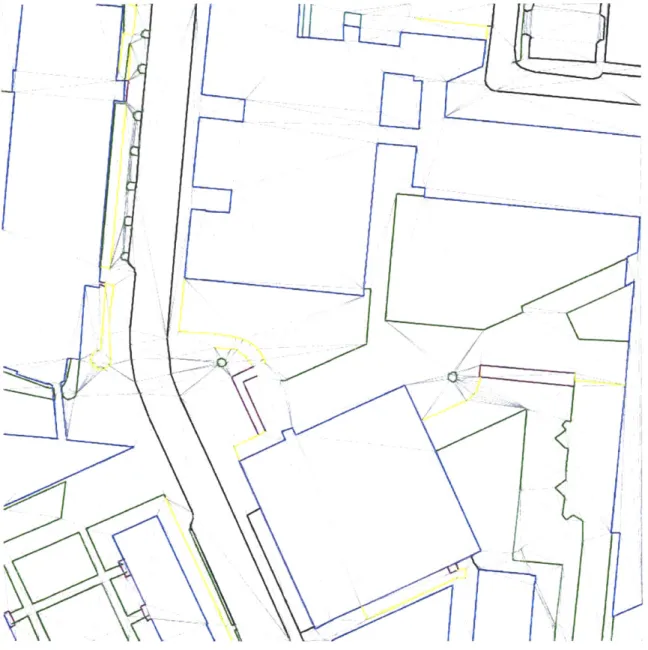
The SL algorithm starts with breaking the basemap into a set of separate, distinguishable spaces. First, the basemap is triangulated by the Constrained Delaunay Triangulation (CDT) algorithm, using basemap contours as constraints [5].
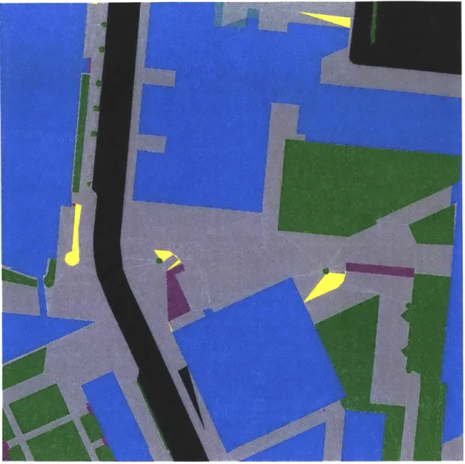
Figure 2-2: Basemap Generator Application in the Debugging Mode: TRIANGULATOR process.
Once the basemap is triangulated, it is subdivided into a set of separate spaces with the following two assumptions in mind: no two adjacent spaces must share the same type, and no two triangles in a space must share an edge from an original basemap contour. The first assumption guarantees that each homogeneous area in the basemap consists only of a single space. The second assumption ensures that each space is bounded by one or more contours from the original basemap. The Basemap Generator program exploits the two assumptions above to break the original basemap into a set of separate spaces, using a simple flood-fill algorithm.
While breaking the basemap into a set of distinguishable spaces is a simple problem in theory, in practice, the implementation of the algorithm is complicated by the fact that contours in the original basemap are not always correct. For instance, in many cases, two contours that are supposed to form a T-like juncture overlap or have a gap between them. While the CDT algorithm corrects many such cases by imposing a fine-grained grid and forcing each vertex to match the closest grid node, some of the gaps and overlaps are not eliminated. Therefore, in addition to the two main constraints discussed above, the flood-fill algorithm implemented in the Basemap Generator application makes use of a supplementary constraint that forbids any flow through triangles with the area-to-perimeter ratio less than 0.01 basemap units, that is, small or thin triangles.
Figure 2-3: Examples of the Erroneous Contours. Invalid T-junctures and contour gaps are marked with purple boxes to
the left and to the right, respectively. 0
-I
4'
5
Figure 2-4: Basemap Generator Application in the Debugging Mode: PATCHBUILDER process.
Once the basemap is broken into a set of distinguishable spaces, the SL algorithm estimates the probability of each space being of a particular type. The way the probability values of a particular space are estimated is by examining the type of each contour in the space boundary and using a predefined table to lookup the estimated probability values (see Appendix C). For example, if the space is surrounded by a single CBLDG contour, the space is most likely to be a building, even though there is a nonzero probability that the space is a sidewalk or a lawn of grass (for instance, the space may be a courtyard surrounded by two or more buildings). Similarly, if the space is surrounded by a CBLDG and a LSITEWALK contours, the space is
most likely to be either a sidewalk or a grass lawn. For any two contour types present in the space boundary, the probability table contains estimates of how likely the space is to be a building, or a sidewalk, or a grass lawn. The weighted average of those estimates
across all pairs of contour types in the space boundary defines the set of probability values assigned to the space. The type with the maximum probability value is the type that is initially assigned to the space.
Figure 2-5: Basemap Generator Application in the Debugging Mode: PROBASSIGNER process.
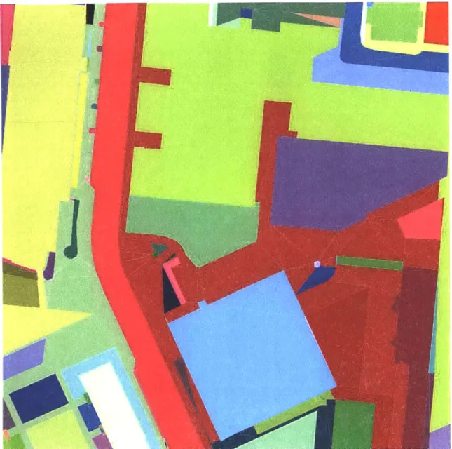
Once the probability values are calculated and each space is labeled with an initial type, the space labeling must be refined, and any possible labeling conflicts between adjacent spaces must be resolved. A labeling conflict may occur when two or more adjacent spaces share the same type, which contradicts how the spaces were constructed in the first place. In order to resolve the conflict, each space is assigned a weight, simply the area of the space. If a space has a neighbor with a larger weight and the two spaces share the same label type, the space with a smaller weight must be assigned a different type - the best possible non-conflicting type. The types are reassigned again and again across the basemap until there are no conflicts to resolve. Each iteration is guaranteed to fix the type of at least one space (the space with the largest weight among the spaces with unfixed types); therefore, the process must converge. The resultant space labeling is the final labeling.
The SL algorithm described above is not the only way to approach the space-labeling problem. A different approach, considered during earlier stages of the program development, was to generate a set of random lines going across the basemap and optimize the type-labeling along each of those lines using a dynamic programming technique. The problem with this approach, however, is that it does not necessarily resolve space-labeling conflicts in all directions, which makes the quality of the label assignment much worse. Moreover, solving the problem in many different directions is a much more time-consuming procedure than assigning the labels using the currently implemented SL algorithm.
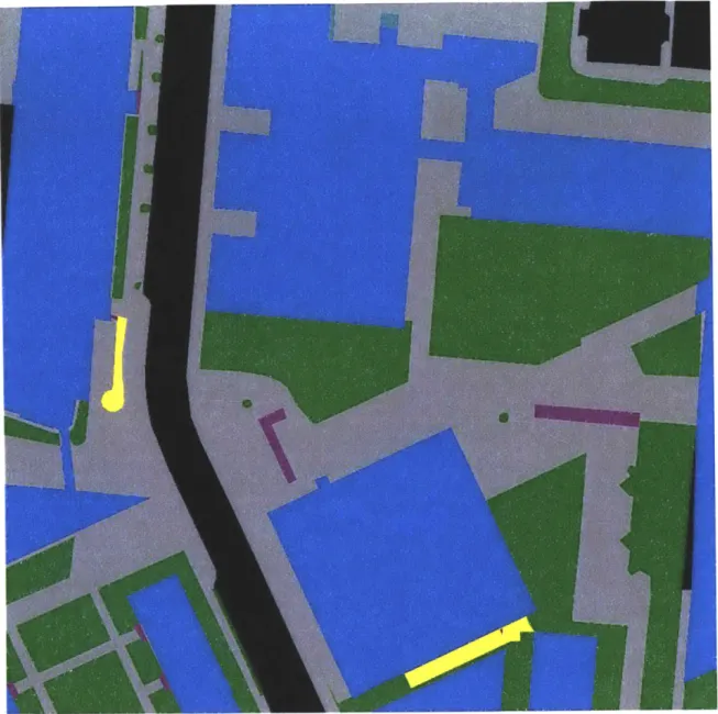
Figure 2-6: Basemap Generator Application in the Debugging Mode: TYPEASSIGNER process.
The SL algorithm makes correct assignments in most cases. The cases that the algorithm handles poorly are those where two or more spaces in the basemap are incorporated into a single large space in the program, because the spaces are not completely separated from each other in the original basemap (see Figure 2-3). Moreover, the algorithm often makes a mistake of assigning a grass type to a sidewalk space or vice versa, because grass and sidewalk types may be used interchangeably in many cases across the basemap. The latter kind of mistake can be fixed using the Basemap Examiner application described later in the text.
Labeling the basemap is only one part of the Basemap Generator task. In addition, the properly labeled basemap must be broken into a set of simpler spaces used by the route generation program, and triangles overlapping with building placement sites must be removed from the basemap model. The reason why the basemap must be broken into a set of simpler spaces is that the route-generation program currently operates only with spaces that are simple polygons, i.e., polygons that have a single, continuous boundary. Therefore, in cases where, for example, a building space completely contains a sidewalk space, the SL algorithm must break the outer building space into a couple of simple spaces. The spaces are subdivided using a flood-fill algorithm. In addition to the constraint of the space simplicity, several other constraints are imposed. For instance, currently, no space is allowed to contain more than a predefined number of triangles.
Figure 2-7: Part of the Basemap Corrected Using the Basemap Examiner Tool.
Because the basemap model is eventually assembled with models of the newly generated buildings to form a complete model of the MIT campus, it is important to remove any triangles that overlap with building model placement sites from the basemap model. In order to remove the triangles, the Basemap Generator application reads a set of building placement contours, adds them as additional constraints into the original basemap triangle mesh, and then uses a flood-fill algorithm to mark the triangles that must be removed. The marked triangles are skipped during the output stage to produce a well-formed model of the MIT campus terrain.
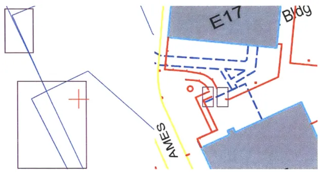
One of the fundamental problems with the approach above is that building contours in the original basemap file represent the top-down view of each building, while the building placement site coordinates come from the outline(s) of the building ground-level floor. There may be a substantial difference between the two types of the building contours, and there is no easy way to make the contours match without modifying the building size or geometry. In addition, because the top-down and the ground-floor contour views of each building are given in different coordinate systems, a set of transformations is needed to make the contours match, at least approximately. The Building Mapper application (see Appendix A.2.4), written in the course of the project in addition to the three main applications discussed here, provides functionality for computing the correct set of transformations.
0C
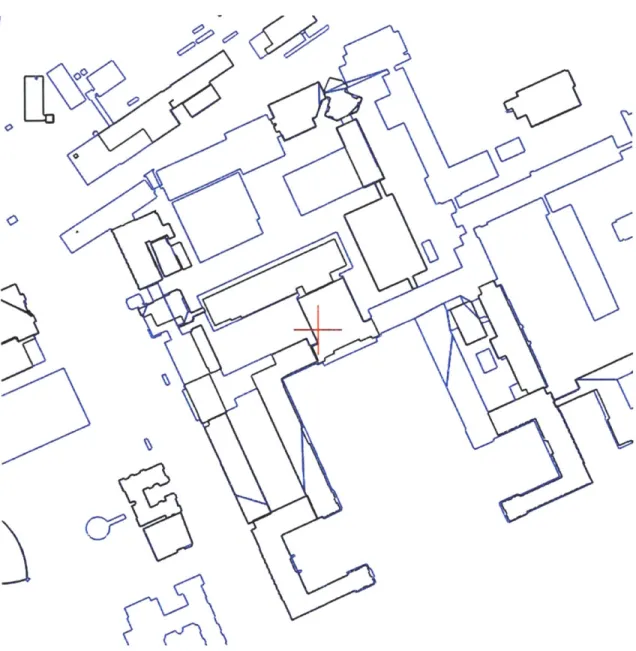
Figure 2-8: Building Mapper Snapshot. Building contours from the contours file are shown in black and the building contours from the .TOPO basemap file are shown in blue.
2.2 Basemap Examiner
The Basemap Examiner application uses the output from the Basemap Generator to examine the two-dimensional basemap model and, possibly, fix some of the labeling errors made by the Basemap Generator. In the Basemap Examiner application, the user is allowed to traverse the basemap and to reassign label types as necessary. For instance, to assign a building type to one of the spaces, the user simply needs to highlight the space and to press a B key (see Appendix A.2.2). Once a building type is assigned, the application uses the space labeling refinement algorithm described earlier to reassign the types of spaces around the space in question, and so on, until there are no labeling conflicts. Once the user is satisfied with the quality of the labeling, the user closes the program, and the new space-labeling information is written onto the disk in order to be further used by the Basemap Modeler application.
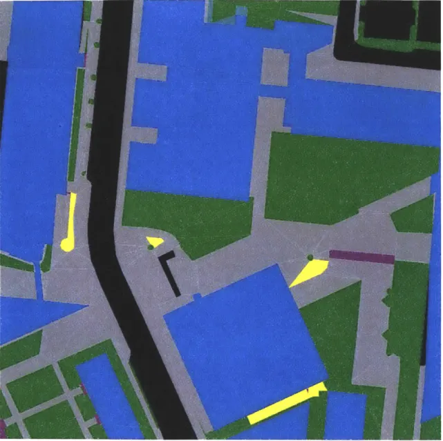
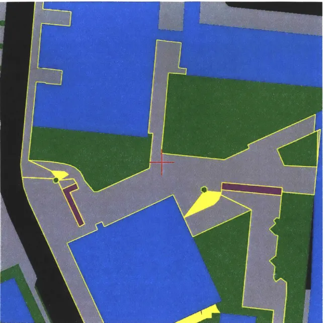
Figure 2-9: Basemap Examiner in the Debugging Mode. Note how the currently active spaces are highlighted with the yellow color.
2.3 Basemap Modeler
The Basemap Modeler application uses the output from the Basemap Examiner application along with the topographic maps obtained from the DOF website to extrude the two-dimensional model of the MIT campus terrain into 3D (see Appendix A.2.3). The DOF provides two different types of topographic maps: isomaps (files with .CONTOURS extension) that contain information about basemap contours that correspond to the same elevation level, and point-by-point maps (files with .POINTS extension) that consist of a large set of points in 3D more or less uniformly scattered around the campus (see Appendix B.7-B.8). The Basemap Modeler application currently makes use only of the point-by-point topographic maps.
The Basemap Modeler uses the three-dimensional points from the point-by-point topographic map of the campus as constraints for the CDT triangulation algorithm, in addition to the regular constraints imposed by the Basemap Generator application. Once the basemap is triangulated, for each contour point from the original basemap file, the
program identifies a triangle in the topographic map that contains the point and uses the triangle vertices to compute the Z-coordinate of the point in question such that the point lies within the plane formed by the triangle vertices (see Chapter 3 for more details). Once all of the basemap vertices are extruded into 3D, a flood-fill algorithm is used to identify the set of triangles within each input space contour to produce a three-dimensional version of the .SPACES (see Appendix B.1) file used by the route-generation program.
F&e OPdvlo OpfhARW
-I
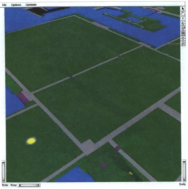
Figure 2-10: 3D Model of the MIT Campus Terrain as Viewed from the ivview Application Window.
Chapter 3
Implementation
Applications such as Basemap Generator, Basemap Examiner, and Basemap Modeler have a lot of functionality in common. In order to avoid the duplication of the code among the programs, the most common functionality has been implemented as a set of separate static libraries. Each application is linked to whatever libraries it needs to use in the compile time, and many applications share the same set of libraries. Once a library is modified, recompiled, and re-linked with the applications that use the library, the change in the library propagates to all the applications. One could allow each application to link to the latest version of the library dynamically, in the run time; however, while convenient, such functionality is supported differently across different platforms.
Each static library in the project is responsible for implementation of a particular piece of the functionality common to all the project applications. Currently, there are four different libraries: Common, FLParser, Geometry, and Graphics. The Common library embraces the most common functionality used not only by all the applications in the project but also by the rest of the static libraries. The FLParser library implements the common file and command-line parsing functionality. The Geometry library provides implementation for a wide range of geometrical data structures and some related auxiliary functionality. Finally, the Graphics library provides implementation for the common
bitmap routines as well as for miscellaneous world window and viewport transformations. The next several paragraphs cover each of the libraries and their classes in more detail.
I:--Figure 3-1: Overall Structure of the Basemap Generation System. Note the three software layers: the application layer and two library layers.
Basemap Generator Basemap Examiner Basemap Modeler
FieParser Geometry Graphics
3.1 Common Library
The Common library implements the functionality most common to the project applications and libraries. It consists of six classes: CMTime,
CMRepository, CMObject, CMTimeCounter, CMStepCounter, and
CMCounter. The CMTime class is responsible for implementation of common time and date functionality, which is implemented differently across UNIX-like and MS Windows platforms. The class encapsulates the platform differences and provides methods that can be used to get all the necessary time and date information. One of the direct users of the CMTime class is the CMTimeCounter, which is used to give a child process the control over the program for a limited amount of time. Once the time, usually measured in milliseconds, given to the child process expires, the control returns to the parent process, which is often responsible for interactive functionality, such as resizing the application window or redrawing the screen.
The CMStepCounter class implements a functionality similar to that of
the CMTimeCounter, but instead of giving a limited amount of time to
the child process, it allows the process to be executed a limited number of times. The counter starts with some predefined number of times to execute the process and decrements every time the process is executed. Once the counter value drops to zero, the control is passed
back to the parent process. The CMCounter class embraces the functionality of both time and step counters. An application that makes
use of the cMCounter class can switch between the two counter kinds in the run time.
CMCounter
CMTimeCaunter CMStepCounter
CMllme
CMObject
CMRepository
Figure 3-2: Modular Dependency Diagram of the Common Library. Every small arrow represents a "uses" relation between the two classes it connects. Every large arrow (not shown on the picture) represents an "is a" relation between the classes it connects.
While time and counter classes find their use in some of the project applications, the CMRepository and the CMObject classes make their
dependencies among producer and consumer classes, and, second, it implements object-tracking functionality that can be used for tracking dangling pointers and deallocating objects that must be deallocated no matter whether the program successfully finished the execution, or failed as a result of a fatal error.
The object-storing part of the repository functionality acts as a dispatcher unit, where miscellaneous objects can be registered and retrieved by a unique string name. In general, multi-level repositories are allowed, that is, repositories can be added to one another to form an acyclic oriented graph. However, as a matter of practice, one or two different repositories per application are usually sufficient, unless one wants to have multiple repositories with multiple namespaces: each repository acts as a separate namespace. No matter how many repositories are in the application, there is generally one or a few global repositories that can be accessed from anywhere in the application. Once an object to be stored in a particular repository is ready, the object producer adds it into the repository with a name known to all of the potential object consumers. Then, an object consumer can simply use the object name to retrieve the object from the repository.
In a large project with multiple separate parts, the repository functionality is necessary to decrease the number of dependencies among the project pieces. Without any kind of a global repository, each object consumer must know about the existence of the corresponding producer and must depend on the producer to create the object in question and to inform the consumer that the object is
ready to be used. This approach leads to additional dependencies between the object producer and its consumers as well as to miscellaneous synchronization issues. The producer must guarantee that it does not return the object only half-ready to be used. With a repository, on the other hand, the producer can simply register the object when the latter is ready. If any consumer attempts to retrieve the object from the repository beforehand, no object will be found in the repository and the NULL pointer will be returned.
The object-tracking part of the repository functionality keeps track of object pointers and deallocates the objects that must be deallocated no matter how the program finishes its execution. Once an object makes it to a global repository, it resides there until either the object is removed from the repository or the application is terminated by a return or an exit instruction. If the application is terminated, the object destructor is indirectly called on the object by the repository. In the object destructor, the object information as well as, possibly, some debugging information can be written to disk and, if necessary, restored once the user restarts the application.
The above scenario is especially useful when the application in question makes use of the GLUT library, which encapsulates a lot of platform-specific OpenGL initialization and window management routines. Because the window exit event is implemented differently across different platforms, the GLUT library does not support
instruction. Then, the memory used by the program is automatically reclaimed by the operating system and no object destructor is called unless the object is global. Because making the object global exposes it throughout the application, a better approach would be simply to register the object in the global repository and then allow the latter to call its destructor automatically.
In fact, with a few minor changes, it is possible to guarantee that any object registered in a global repository will be deleted exactly once at some point in the application life. Because each object to be stored in a CMRepository must inherit from the CMObject class, the programmer can make sure that the object is added to the repository when it is created and removed from the repository when its virtual CMObject destructor is called. This approach will work both for static and non-static objects, for while it is true that the order in which static-global objects are deallocated by the system is not defined, each static object is destroyed exactly once. This kind of functionality can be easily added provided that each object stored in a repository knows the unique name by which it is referenced within the project.
The CMObject class also serves two goals. First, as mentioned above, every object that needs to be stored in a CMRepository must inherit from the CMObject. In fact, because the class is used almost everywhere throughout the project, the CMObject is also the class that contains the global static repository, and static methods are provided to add, remove, and retrieve objects from the repository. Second, the CMObject class provides warning and assertion functionality along with
definitions for common error and warning messages. The difference between warnings and assertions throughout the project is that the former simply redirect the warning messages to the standard output, while the latter also halt the program by making a call to the C/C++ exit instruction. Once the program is halted, the standard procedure of deallocating global repositories along with objects stored there applies. One may change this behavior by making a call to the C/C++ abort function, in which case no objects will be deallocated and the memory will be reclaimed by the operating system.
3.2 FLParser Library
The FLParser library implements the common file and command-line parsing functionality. It contains the following classes: CLParser,
FLToken, FLTokenizer, FLParser, UGNode, and UGNodeIR, as well as a
dozen other smaller classes that are used by the Unigrafix format parser. The CLParser class incorporates functionality common to all the command-line parsers in the project. More specifically, it allows the user to specify from the command line the name of the main data file to process, a special "-frmt" flag that indicates the format or formats that must be used for outputting debugging information, a "-mode" flag that indicates whether the program must be run in a debug or batch mode, and a "-help" flag that indicates a request for the
command-line parser, which can usually be found by a name that consists of a two-letter application name abbreviation and a "Parser", suffix; for instance, "BGParser," "BEParser," and so on. Usually, each of the command-line parsers inherits from the CLParser and overrides or extends the functionality of the latter.
The FLParser class as well as its helper classes, the FLToken and the
FLTokenizer, all serve to provide file-parsing functionality. Each class
that extends the FLParser class inherits an individual tokenizer that breaks the input file stream into a sequence of tokens, where each token extends the FLToken class. Two groups of characters are used to
break the stream into tokens and those characters may differ from one parser to another. The first group of characters usually consists of separation characters such as space, tab, or a new line. The second group consists of characters that are often used to separate tokens but that serve as tokens as well. For instance, left or right curly brace characters often make it into the second group, because these tokens are usually used to separate numbers or other tokens in miscellaneous graphics formats.
In order to provide elementary parsing error functionality, each token contains information about the line and position it comes from in the original data file. This way, if an error occurs while parsing an input, the parser can get back to the user with a comprehensible error message that specifies the type of the error along with the location where the error occurred in the data file. Apart from the common error diagnostic functionality, the FLParser class also contains functionality
for parsing integer and real numbers. If two or more file parsers in the project inherit from the FLParser and have a lot of the additional
functionality in common, the common functionality is usually encapsulated in a separate class that also inherits from the FLParser,
directly or indirectly. For instance, the VXParser class in the Geometry
library inherits from the FLParser and provides vertex-parsing functionality for all file parsers that deal with vectors and vertices in the common {X Y Z} format.
UGCrgb UGVrtx UGWire UGFace Figure 3-3: Library. CMObject CLParser UG Fde
Modular Dependency Diagram of the FLParser
FLParser
FLTokenizer
the FLParser was added to the project after the .UG parser had already been implemented. Unlike file parsers that inherit from the FLParser class, the .UG parser does not break the input into a sequence of tokens explicitly. Instead, the parser first creates an intermediate representation of the input file data and then converts the intermediate representation into a set of actual Unigrafix objects. If a parsing error occurs and no intermediate representation can be created from the input, the parser halts before it allocates any Unigrafix objects. The approach above is beneficial when the intermediate representation data structures are lightweight compared to heavyweight representation of actual Unigrafix objects.
3.4 Geometry Library
The Geometry library provides implementation for a wide range of geometrical data structures and related auxiliary functionality. The library consists of four different groups of classes. The first group provides implementation for N-dimensional vectors and points as well as lines, segments, and other geometrical primitives. The second group represents a modified version of the Constrained Delaunay Triangulation (CDT) library. The third group provides implementation for miscellaneous polygon data structures as well as the multigraph data structure built on top of the Quad-Edge triangle mesh. Finally, the last group of classes is responsible for outputting geometrical data in Unigrafix, Open Inventor, and other file formats. The next several paragraphs describe each of the four groups in more detail.
GMColor GMS
GM ntr GLStream IVStream PSStream UGStream
L
GMS GMGroup GMPoly GMCncv
GMLocator GMBucket
GMNode MLlterator
One VectorND Segment2d GMGraph
PtorND
E-so_
GMEdge C~jc GMClipper Edge MeshQuadEdge Uist LfistNode
Figure 3-4: Modular Dependency Diagram of the Geometry Library.
The geometrical primitive class group consists of the following classes: VectorND, Line, Segment2d, and GMClipper. The VectorND class
template provides implementation for N-dimensional vectors and points and replaces the deprecated set of two-dimensional geometrical primitive classes that originally came with the CDT library. Generic,
N-be laN-beled with one of the N different laN-bel types and there is a probability value indicating how well each of the label types fits the triangle, it is possible to think about the probability values forming a probability vector in an N-dimensional space. Then, for any two adjacent triangles in the basemap, the larger the dot product of the corresponding probability vectors, the more likely it is that the triangles must be labeled with the same type.
The Line and the segment2d classes implement line and segment
primitives. While lines and segments are inherently two-dimensional, in the sense that for each line or segment there exists a plane that contains all of the line or segment points, points in more than two-dimensional space can be used to specify a segment or a line. In such a case, all point coordinates but X and Y are usually discarded. The GMClipper class implements the Cohen-Sutherland clipping algorithm and can be used to clip lines and segments according to a predefined two-dimensional clipping window [6]. The clipping functionality is used extensively throughout the project for processing subsets of large geometrical data sets.
The second group of classes forms a modified version of the CDT library. The library has been modified in several ways. First, the library has been tuned to make use of the new set of generic geometric primitives. Second, the Edge class, responsible for implementation of a
single mesh edge, has been modified to inherit from the GMEdge class that provides an interface for data structures such as the multigraph data structure built on the top of the Quad-Edge triangle mesh. Finally, the CDT algorithm has been adjusted to operate in 3D. For instance,
when a new edge is being inserted into a mesh and the edge intersects one of the mesh edges, each of the two edges is split into two by the common intersection point. While the original algorithm computed only X- and Y-coordinates of the intersection point, the new version of the algorithm also computes the third, Z-coordinate.
The third group of classes provides implementation for miscellaneous polygon data structures as well as the multigraph data structure built on top of the Quad-Edge triangle mesh. The Quad-Edge data structure encapsulates much of the information about the triangle mesh. For instance, given an edge e in the mesh, one can look up the origin of e, the destination of e, the previous and the next edge around the left face of e, the previous and the next edge around the right face of e, all the edges leaving the origin of e, all the edges coming to the destination of e, and so on. However, while the Quad-Edge data structure captures much of the local information about the mesh, it fails to support many global operations such as obtaining a list of triangles in the mesh or obtaining the total number of edges in the
mesh. Therefore, if one wants to obtain the total number of triangles or edges in the mesh, one often has to traverse the whole data structure.
To ensure that the global as well as the local information about the triangle mesh is available, a multigraph dual of the Quad-Edge data structure is built on the top of the Quad-Edge data structure. In the
enough to represent an arbitrary plane subdivision, more than one edge may exist between two nodes-polygons that share more than one edge in the subdivision: this is where the term "multigraph" comes from.
The GMGraph is the class that provides implementation for the
multigraph data structure in the Geometry library. In the GMGraph class, the multigraph data structure is implemented using several STL map containers. Two map containers are used to map each edge to the edge origin and destination nodes, and another two map containers are used to map each node to the list of edges coming into the node and the list of edges leaving the node. Because no node or edge, implemented by classes GMNode and GMEdge respectively, stores any graph-related information as part of their internal states, two or more graphs can share the same set of nodes and/or edges.
While any graph node in the GMGraph class must inherit from the
GMNode, the latter does not provide any information about the
polygons that it represents in the subdivision. Instead, a hierarchy of classes, many of which inherit from the GMNode class, provides all the polygon-related functionality. Each class in the hierarchy represents a set of polygons with particular properties. For instance, most of the polygon classes in the hierarchy inherit from the abstract GMSpace class that provides an interface to the GMLocator class used for identifying the polygon that contains a particular point in the subdivision. Two classes inherit from the GMSpace class: the GMGroup and the GMCntr.
The GMGroup class implements a group of non-overlapping and possibly disconnected simple polygons. The class supports point-locating functionality and provides implementation for methods that return the group area, perimeter, bounding box, type, etc. The GMGroup class also serves as a base class for the GMPoly class that represents a group of non-overlapping, connected simple polygons with a single contour. Further below the hierarchy, two classes, the GMCnvx and the GMCncv, which represent convex and concave simple polygons respectively, inherit from the GMPoly class and provide alternative, more efficient implementations for some of the methods above the hierarchy.
One of the most important methods in the GMPoly class is the AddNode
method responsible for "gluing" two adjacent polygons together. The method is extensively used throughout the project in many flood-fill-like algorithms, where two or more connected polygons in the subdivision are incorporated into a single patch. Because "gluing" two polygons is a relatively expensive operation, it was the AddNode
operation that largely defined the choice for the internal representation of the GMPoly class. In the class, there must exist some representation for the contour of the polygon in question. The most obvious implementation of the contour is a vector or list of vertices. Unfortunately, the obvious representation results in a linear complexity of the AddNode operation, which is too expensive. Therefore, the
edge in the counter-clockwise direction. Another map data structure maps each polygon to the previous edge in the counter-clockwise direction. While such a representation makes it slightly more expensive to traverse the polygon edges in one or another direction, it decreases the complexity of the AddNode operation from 0 (n) to 0
(log n), where n is the number of vertices or edges in the largest of the two polygons being "glued."
Using two maps to represent the polygon contour makes the AddNode
operation much more efficient but takes its toll on operations such as displaying the polygon on the screen. While incremental updating of a single bitmap in the debugging mode works adequately in most cases, displaying thousands of triangles in real time becomes a problem. One way to deal with the difficulty is to cache the perimeter of the polygon in a consecutive or a random access container such as a list or a vector. Then, if the AddNode operation is not called too often, the method responsible for rendering the polygon on the screen may ignore the map representation of the polygon contour and use the cached representation instead. The BEPoly class in the Basemap
Examiner application exploits this strategy. Another approach to avoid the problem is not to provide efficient implementation for the AddNode
method at all, thus preserving the obvious representation of the polygon contour. For instance, the GMCntr class that is mainly used to represent large simple polygons supports all point-locating functionality but does not provide any of the more sophisticated GMPoly methods such as the AddNode method.
The ability to identify the polygon or polygons that contains or contain a particular point is crucial in the project. The GMLocator is the class that provides point-locating functionality. The way the GMLocator works is simple. When an instance of the class is created, the user initializes the locator with a rectangular window that must be tracked, and registers one or more GMSpace objects with the locator. Inside the locator, a rectangular grid is imposed onto the window being tracked and divides the window into a set of separate buckets. In turn, each GMSpace object represents a two-dimensional entity with a rectangular bounding box and a special Locate method that returns true when the space contains a particular point. Then, when a GMSpace object is registered with the locator, the object is added to all the buckets that have any common points with the bounding box of the object. When a space containing a particular point needs to be identified, the locator examines the bucket that hosts the point and searches for a space that admits to containing the point. If such a space is found, the locator returns a reference to the space object; if not, the locator returns NULL.
The last, fourth part of the Geometry library consists of classes responsible for outputting geometrical data in Unigrafix, Open Inventor, and other file formats. The need to output geometrical information in different formats arises from the fact that different formats are popular under different platforms. In addition, some of the formats are more difficult to parse than others and, as a result,
sophisticated formats such as the Open Inventor format are used for visualization purposes.
The group of classes responsible for outputting geometrical data consists of the GMStream base class and several classes that extend it:
GLStream, IVStream, PSStream, and UGStream. The base class
provides several overloads for the stream insertion operator that enable the user to specify the current drawing color as well as the current drawing mode. Presently, three different drawing modes are supported: POLYGON, CONTOUR, and DELAUNAY. The POLYGON is by far the most popular mode, when the polygon in question is rendered filled with the current color. In the CONTOUR mode, only the contour of the polygon is rendered without outputting any contours of the sub-polygons that the polygon in question may consist of. Finally, in the DELAUNAY mode, the contour of the polygon is rendered along with the contours of its sub-polygons.
Each of the subclasses, GLStream, IVStream, PSStream, and UGStream,
writes geometrical data onto the screen, in the case of the GLStream class, or into one of the three file formats: Open Inventor, Post-Script, and Unigrafix. Besides the three file formats supported presently, support for the fourth, the VRML format, is in the process of being added. The output of each stream class consists of three parts: the starting sequence, body, and the closing sequence, where any of the parts may be an empty sequence. When a stream class object is created or deleted, the output starting or closing sequence
respectively is displayed on the screen, in the case of the GLStream class, or written into a file. Failing to delete a stream object allocated
dynamically may lead to an invalid output and/or dangling file handlers.
The GMColor class is used throughout the project for setting the current OpenGL or stream drawing color, as well as for converting from abstract node and edge types to RGBA colors used for visualization. The GMColor class inherits from the generic VectorND
class and represents a vector of four one-byte components: Red, Blue, Green, and Alpha. The class currently provides a standard set of colors
plus a special default color used when the programmer has not set any color explicitly. Moreover, the default color can be used to specify that a polygon being output by an overloaded stream insertion operator of one of the stream classes must be painted with the preset polygon color.
3.3 Graphics Library
The Graphics library provides implementation for the common bitmap routines as well as for miscellaneous world-window and viewport transformations. The library consists of the following classes:
GRPixelMap, GRWindow, GRViewport, GRWorldWin, and GRPortal. The
GRPixelMap class provides implementation for the common bitmap functionality. Each instance of the class is a rectangular matrix of RGBA
debugging mode may need to visualize changes made to a large data structure. While redrawing the entire data structure every time it is modified is often infeasible, making an incremental change to a bitmap copy of the screen contents and displaying the bitmap works in most cases. Because the bitmap content always reflects the current state of the data structure, the time it takes to update the bitmap usually depends not on the size of the data structure but on the number and quality of the incremental changes made to it.
GRPortal GRPixelMap
'/ I
-+ GRViewport GRWorldWin RGBA GRWindowFigure 3-5: Modular Dependency Diagram of the Graphics Library.
Because two or more bitmaps can be displayed on top of each other with arbitrary levels of transparency, more than one stage of the
algorithm can be visualized simultaneously. In fact, because each bitmap is just a matrix of pixel values, it is possible to combine computer-generated images with those loaded from .BMP image files. Currently, the GRPixelMap class supports loading bitmaps from 24-bit .BMP files but does not support saving bitmaps in the .BMP format, a function that may prove to be useful in the future. It would also be useful to provide functionality for reading and writing bitmaps from and to .JPEG and .GIF files as well.
The GRWorldWin, GRViewport, and the GRPortal classes provide
functionality for mapping one or more world-windows to one or more viewports on the screen. Each instance of the GRPortal class represents a one-to-one mapping between a world-window implemented by the GRWorldWin class and a viewport implemented by the GRViewport class. When a portal is activated by invoking a GRPortal: :BringUp method, any image produced by calls to the OpenGL library is clipped according to the portal world-window coordinates, mapped to the portal viewport, cached in the portal bitmap, and displayed in the viewport so long as the portal's visibility flag is set to true. The portal viewports are generally initialized to reflect the initial dimensions of the main application window. If the user resizes the application window, each of the viewports is automatically resized to preserve to the original layout. When a portal viewport is resized, the portal bitmap is usually also resized and redrawn to preserve the one-to-one pixel mapping between the
3.5 Basemap Generator
The Basemap Generator application is structured as a pipeline of separate stages, called processes, executed by a single processing unit, called processor. Each of the processes provides implementation for one part of the Basemap Generator Space-Labeling (SL) algorithm. The processor is responsible for registering and executing the processes, one after another, in a predefined order. The processor also controls a local repository used to help processes to pass data from one process to another. The following several paragraphs describe the processor and each of the processes in more detail.
The BGProcessor class implements all the functionality of the
processor. Because there is a need for only one processor per application, the BGProcessor is implemented as a singleton: the only
constructor that may be used to create a new processor is declared private, and a single public producer method guarantees that only one instance of the BGProcessor class is ever created. When the processor is created, it is added into the global object repository to make sure that the processor and all of the objects stored in the local processor
repository are deallocated from the memory before the application is terminated.
Once the processor is created, it must be initialized. During the initialization stage, each of the different application processes is created and added to the processor execution queue in a predefined order. In the debugging mode, a separate drawer, implemented by the BGDrawer class and responsible for outputting the debugging
information onto the screen, is also created for each of the application processes. The newly created processes, as well as their drawers, if any, are automatically added into the local processor repository. The name for identifying a particular drawer in the repository consists of the name of the host process and a ":DRAWER" suffix. This way, each process in the application "knows" the name of its drawer and, as a result, can obtain a reference to the drawer stored in the processor repository.
CMCounter
CMReposi*]r
CMObject SOPoces
GMCfippef SGDra r BGProcess
Thianguhor G aphBu~er PalchBwuder Pbssne TypeAssgner CutoffMar er Traggregator
Iesh
GMCnvIII3III1 I
GLStream EdeGMPOIy - IVStreamEdgeL L...
GMGraph GMGroup GMStream Psistream
G:Ege
1
j
[Eator GMNode GMC,0r UGStreamlThe BGProcessor class provides a special Execute method that runs
through a small part of the SL algorithm until the algorithm is over.
The Execute method consists of several steps. First, a time or step
counter is initialized and set to a positive value. Then, the current process is executed until either the counter drops to zero or the process comes to an end. Then, in the debugging mode, the changes made to the internal state of the current process are displayed on the screen and information about the process progress is shown at the standard output. If the current process comes to an end, its temporary data structures are deallocated from the memory, and the next process from the process execution queue is initialized to take the place of the current process.
There are two different ways the Execute method can be called in the
Basemap Generator application. In the batch mode, the Execute
method is simply called multiple times until the algorithm is over. In the debugging mode, the Execute is called indirectly by the idle OpenGL callback function. Once the OpenGL main loop is started and until the application is terminated, the idle function, registered along with several other special OpenGL callback routines, is called automatically every time the application is idle.
The Display method of the BGProcessor class is responsible for displaying the debugging information about the current process in the debugging mode. For each process that has already been executed or is in the process of being executed, the corresponding process drawer is retrieved from the processor repository, and the drawer bitmaps are
displayed with predefined levels of transparency, one for each portal in the drawer. The Display method is called indirectly by the display OpenGL callback function every time the image on the screen needs to be updated.
The Reshape method of the BGProcessor class is responsible for
rescaling and possibly redisplaying the debugging information on the screen after the main application window has been resized. The
Reshape method is called indirectly by the reshape OpenGL callback
function called every time the main application window is resized. The
Reshape method takes two parameters: the new height and width of
the window. For each of the application processes, the Reshape
method retrieves the corresponding process drawer from the processor repository, resizes the drawer bitmap, and updates the bitmap content by making a call to the processor Repaint method.
There are seven different processes in the Basemap Generator: TRIANGULATOR, GRAPHBUILDER, PATCHBUILDER, PROBASSIGNER, TYPEASSIGNER, CUTOFFMARKER, and TRAGGREGATOR. Each of the
processes inherits from the BGProcess class that provides default
functionality for initializing, executing, and debugging each process.
The Triangulator class implements the TRIANGULATOR process. In
the Execute method of the Triangulator class, the basemap space
contours are read from the basemap .UG database, clipped as necessary, broken into a set of separate edges (each edge with a
![Risiko- & [und] Schutzfaktoren der psychischen Gesundheit humanitärer Einsatzhelfer : eine systematische Literaturübersicht](data:image/gif;base64,R0lGODlhAQABAIAAAP///wAAACH5BAEAAAAALAAAAAABAAEAAAICRAEAOw==)