HAL Id: insu-01356027
https://hal-insu.archives-ouvertes.fr/insu-01356027
Submitted on 24 Aug 2016
HAL is a multi-disciplinary open access
archive for the deposit and dissemination of
sci-entific research documents, whether they are
pub-lished or not. The documents may come from
teaching and research institutions in France or
abroad, or from public or private research centers.
L’archive ouverte pluridisciplinaire HAL, est
destinée au dépôt et à la diffusion de documents
scientifiques de niveau recherche, publiés ou non,
émanant des établissements d’enseignement et de
recherche français ou étrangers, des laboratoires
publics ou privés.
Influence of Some Rheological Parameters On Flexure of
the Oceanic Lithosphere
Andrei A Panteleyev, Michel Diament
To cite this version:
Andrei A Panteleyev, Michel Diament. Influence of Some Rheological Parameters On Flexure of the
Oceanic Lithosphere. Geophysical Journal International, Oxford University Press (OUP), 1992, 114,
pp.209-220. �10.1111/j.1365-246X.1993.tb01480.x�. �insu-01356027�
Geophvs. .I. Int. (1993) 114,209-220
Influence of
some
rheological parameters
on flexure
of
the oceanic
lithosphere
A. N. Panteleyev'?" and
M. Diament2
'
Insritirte of Phvsics of the Earth. 10 B. Gruzinskaya, 0-242 Moscow. Russia'
Institiit de Physique dlc Globe de Parij, Laboraroire GraviniPtrie et GPoc/vnatniqlre, Case 89. 4 Placc Jrcssierc. F-75252 Paris 05, France Accepted 1992 December 21. Received 1992 December 21; in original form 1991 December 30S U M M A R Y
Rheological parameters describe properties of the lithosphere, but it is generally impossible to measure them
in
situ. Thus a model has to be developed to relate parameters to observables. We consider flexure of the oceanic lithosphere. A quantitative representation of a brittle-elastic-ductile rheology is based on a semi-empirical model. The non-linear problem of plate flexure is solved by the multiple-shooting algorithm using a Runge-Kutta procedure from analytical solu- tions for an elastic model. The bending moment and its derivatives have been deduced analytically to improve the accuracy and speed of computations. A family of numerical solutions was built that describes flexureof
the oceanic lithosphere at subduction zones for various ages, strain rates, and activation energies. Relative contributions of rheological parameters are discussed. The model is then usedto
evaluate rheological parameters of the Kuril trench from gravity data. The strain rate estimates are found to be about3
.
10-('6*1)s-1 assuming creep activation energies between520
kJ/mole and 550 kJ/mole for lithospheric age ranging from 90 Ma to 110 Ma.Key
words: flexure, gravity, oceanic lithosphere, rheology.I N T R O D U C T I O N
Various observable features in the ocean, such as outer rises on the oceanic sides of deep-sea trenches or moats flanking seamount chains, are explained by flexure of the oceanic
lithosphere (Vening-Meinesz 1941; Gunn 1943). Many
studies showed that flexure of the lithosphere depends on whether the lithosphere is elastic (e.g. Vening-Meinesz
1941; Gunn 1943; Hanks 1971; Watts & Talwani 1974;
Parsons & Molnar 1976; Caldwell et al. 1976), viscous (De
Bremaecker 1977), viscoelastic (Melosh 1978), perfectly plastic (Lobkovsky & Sorokhtin 1976), or elastoplastic (McAdoo, Caldwell & Turcotte 1978; Turcotte, McAdoo &
Caldwell 1978; Bodine & Watts 1979; Chapple & Forsyth 1979). Thus rheological parameters describe mechanical properties of the lithosphere (Kirby 1977; Goetze & Evans 1979; Brace & Kohlstedt 1980; Kirby 1983; Kirby &
Kronenberg 1987; Ranalli & Murphy 1987). In fact,
rheology controls stress and deformation of the lithosphere subjected to external forces, such as loads, as well as the evolution of deformations with time.
* Presently at lnstitut de Physique du Globe de Paris, Laboratoire Gravimetric et GCodynamiquc, Case 89, 4 Place Jussieu, F-75252 Paris 0 5 , France.
On the basis of the realistic brittle-elastic-ductile rock rheology of the oceanic lithosphere, Goetze & Evans (1979) suggested a multiple-layer model represented in terms of the yield stress envelope (YSE). The model was used by many authors (e.g. Bodine, Steckler & Watts 1981; McNutt &
Menard 1982; McAdoo, Martin & Poulouse 1985;
Chamot-Rooke & Le Pichon 1989). This model appears to explain successfully flexure observations as well as to overcome limitations of the purely elastic model (Deplus 1987) that fails to predict steep bathymetry slopes for many trenches (Caldwell et al. 1976) and generally requires stress
in rocks which is too high based on experimental data o n rock mechanics.
According to the model, in particular, flexure of the lithosphere is controlled by creep laws that act in the ductile part of the lithosphere and involve strain rate, physical state (temperature) and properties (creep-activation energy) of the rock. The thermal structure of the oceanic lithosphere has been widely discussed (e.g. Turcotte & Oxburgh 1967; Parker & Oldenburg 1973; Parsons & Sclater 1977; Cazenave 1984; Denlinger 1992; Stein & Stein 1992) and
seems rather well evaluated. Creep activation energy is
known from laboratory experiments (Goetze & Evans
1979). Finally, difficulty in measuring in situ does not permit
209
at INIST-CNRS on August 23, 2016
http://gji.oxfordjournals.org/
210 A. N . Panteleyev and M . Diament
us to obtain directly present values of strain rate, but several
authors have estimated them (Goetze & Evans 1979;
Chapple & Forsyth 1979; Bodine et at. 1981; McNutt &
Menard 1982).
Nevertheless, no complete analysis of the trade-offs
between these parameters has been carried out previously. Our goal in the paper is to develop a numerical method to
compute flexure of the oceanic lithosphere in order to better address this question and to investigate if in situ estimations
of these parameters could be obtained by studying flexure.
R H E O L O G Y M O D E L
To treat the brittle-elastic-ductile rheology, we reduce it to the multiple-layer elastoplastic model described by means of YSE (e.g. Goetze & Evans 1979; McNutt & Menard 1982; McAdoo et al. 1985). Corresponding values of the highest
permissible difference of the principle stresses,
ha,,, = ( a , - uJmax or rather its signed modification A u r as determined by semi-empirical laws, are assigned to each lithospheric level for both compression and tension.
Upper layers of the oceanic lithosphere are exposed to brittle failure and to frictional sliding on fault surfaces. The process is controlled by Byerlee's laws (Byerlee 1978) (following Byerlee, we treat compressive stress as positive):
T = 0.85 u, at ~ ~ ~GPa 0 . 2 ( l a )
T = 0.6~7,
+
0.05 GPa at 0.2 GPa < u, < 2 GPa (Ib)where ~7~ is the normal (confining) stress, and T is the highest permissible tangent (breaking) stress. Using Mohr's circle diagram it is possible to show that the result is nearly a linear dependence of A u r on depth (see Appendix A for details).
Following McAdoo er al. (1985), we describe A u r in the
upper oceanic lithosphere by means of two vertical gradients
only: yBc = 0.66. lo5 Pa m-' for compression and
yBT = -0.22 . 10' Pa m-l for tension. This approach does not take into account explicitly the sea-water loading and gives absolute values of Au, somewhat smaller than those
from more accurate formulae derived in Appendix A.
However, both descriptions seem to be more or less
adequate, since water can penetrate into the upper layers of the oceanic lithosphere. The possible resulting serpentiniza- tion and filling of pores by fluids may then substantially decrease the strength of rocks (Kirby & Kronenberg 1987).
In general, rheology of the upper oceanic lithosphere is defined by lithostatic pressure only. It depends on the depth and, t o some extent, on the specific vertical density distribution.
Lower layers of the oceanic lithosphere obey the
power-creep law (2b) and its modification at higher
differences of the principle stresses in Peierl's region (2a) (Goetze & Evans 1979):
at ~7~ - u 3 > 0.2 GPa
at u I - u3 0.2 GPa
where T is absolute temperature in K , t? is strain rate in sCI,
R = 8.314 J / ( K
.
mole), C, = 5.7 . 10" s I, C, = 7.0.sCI PaC3, uo = 8.5 GPa; Q , = 536 kJ/mole and Q, =
523 kJ/mole are respective activation energies. u , and LT? are the maximal and the minimal principle stresses respectively so that always w , - v 3 2 0. Unlike Byerlee's laws ( I ) , there is no dependence on LT". As a result, relative to compression and tension the laws (2) are symmetrical.
The relations (2) are obtained from experimental studies of dunites containing dry olivine that represent the upper mantle rocks. According to (2), the relationship between t.
and u I - u 3 strongly depends on temperature, hence on depth below the surface of the plate and on the lithospheric age.
The temperature distribution with depth is computed using cooling models of the oceanic lithosphere. Since recent studies note opposing effects that can place standard isotherms both shallower (Stein & Stein 1992) and deeper (Denlinger 1992) than generally accepted cooling models predict, we adopt, following McAdoo et a/. (1985), the simple half-space model (Turcotte & Oxburgh 1967; Parker
& Oldenburg 1973) for ages 80 Ma or less:
T = 7;, erf {~/[2(kt)"~]}, t < 80 Ma (3a)
and for ages greater than 80Ma we use the following first-order approximation of the plate model (Parsons & Sclater 1977):
where T is temperature, "C, To is zero-age temperature, k is thermal diffusivity, t is age,
z
is depth, a is thermal platethickness. We use 7;, = 1300 "C, a = 125 km, and
k = loCh m2 s-'.
We deal with lithospheres older than 30 Ma, so we do not need to distinguish the young lithosphere cooling regime (Cazenave 1984) as well as formation processes of the lithosphere in the vicinity of mid-ocean ridges. We perform computations to an age of 160 Ma.
T o constrain YSE, we fix different strain-rate distributions with depth in the lower oceanic lithosphere (e.g. Goetze &
Evans 1979; Bodine et al. 1981; McNutt & Menard 1982;
McAdoo et al. 1985; Chamot-Rooke & Le Pichon 1989).
Each distribution is considered to be the limit of the elastic stress and the border between elastic and plastic regimes, such that the strain rate and the temperature of a layer are unequivocally associated with Aur. We varied the strain rate
from s-' to s-'; assuming that strains of a few
per cent develop over 107yr, a simple kinematic scheme (e.g. Goetze & Evans 1979) gives t = lo-" s-I, whilst more
elaborate estimates provide strain rate from 10C1's-' or
lO-"s-' under seamounts and up to 10C" s C L or lo-" s - at subduction zones (Bodine et al. 1981; McNutt & Menard 1982). Other authors (e.g. Chamot-Rooke & Le Pichon
1989, and McAdoo et al. 1985, for the lower oceanic
lithosphere; Fadaie & Ranalli 1990, for the continental one) usually assume strain rate to be of the order of lO-"s-' or
A change in the strain rate by an order of magnitude makes a noticeable effect on YSE that is larger than the
error introduced by the approximation of YSE (see Fig. 1).
The depth where the linearized A u r equals zero is
sC' to model rheology.
at INIST-CNRS on August 23, 2016
http://gji.oxfordjournals.org/
Influence of rheological parameters 21 1 T e n s i o n AD. 1 0 ~ P a Compression - 1 U -8 - 6 -4 -2 0 2 4 6 ti 10 12 14 16 18 20 i _ . i - _ i _ l , , I
.
, ~ , , , I , . 1 T e n s i o n A D . ] @ P a Compression - l U -8 - 6 -4 -2 0 2 4 6 ti 10 12 14 16 18 20 m L . k mFigure 1. YSE for the oceanic lithosphere, i.e. A u r (see text and
Appendices), 10' Pa, horizontal axis, versus depth from the top of the lithosphere, km, vertical axis. Curves arc shown for 9 0 M a old lithosphere. Byerlee's laws I ( l a ) and Il(1b) are shown for the upper lithosphere as deduced in Appendix A, eq. (A12), in as much as the linear approximation after McAdoo et al. (1985) was used for computation (dashed lines). Three values of the lower lithosphere strain rate are shown: 10 ' ' s I, 10 ''s-',
. .
T h e linearized A u r arc also shown with dashes. 13ifferences of the principle stresses A u in the intermediate elastic layer are shown by dotted line. T,,,denotes the thickness of the mcchanical lithosphere, zF3 and z~
designate the upper and the lower depth borders of the elastic layer,
q, shows the neutral plane that does not coincide generally with the middle plane of the plate due to the asymmetry of YSE. T h e
vertical gradients o f ACTr are denoted by y s c . (brittle comprcssion). yo-r (ductile tension), yt3,- (brittle tension), and yIJc. (ductile comprcssion).
considered to be the base of the mechanical oceanic lithosphere, zh. T h e thickness of the lithosphere above this level corresponds t o the thickness of the mechanical lithosphere, T,. As a result the lower part of YSE can be
described by means of two values: T, and the absolute value
of the vertical gradients of Aurr y L = lyDTl = JyDcJ. Since
Log10 IStrainRatessl
-19 -18 - 1 7 -16 - 1 4 - 1 %
19 -18 - 1 7 -16 -15 - 1 4 -13 Log10 I S t r a i nRa t e * s l
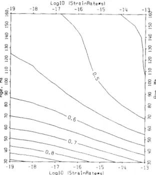
Figure 2. Absolute value of the vertical gradients of Aur in the
lower ductile part of the oceanic lithosphere, yl,, 10' P a m I, a s a
function of the strain rate i: log,,, [ k ( s I) . s], horizontal axis, and
the lithospheric age, Ma, vertical axis.
the upper part of YSE has a constant description, T, and y ,
are the only variable parameters of the model.
The 2-D distributions of values of T, and yL with the lithospheric age and with the strain rate were computed.
Figs 2 and 3(a) show that (and how) ancient oceanic lithosphere subjected to slow deformations (low strain rate) at its base has the same strength properties as the younger oceanic lithosphere subjected t o faster deformations. This tendency was previously noted by Bodine et al. (1981).
Our computations show that the temperature at the base
of the plate (depth
z,)
depends o n strain rate at a given activation energy (Table 1): if the strain rate is higher, then warmer zones of the lithosphere are included in T,. ItLog10 l S t r a i n R a t e * s l
lli - 1 3
- 1 9 -18 - 1 7 - 1 6 -1s Log10 l S t r a i r , R a t e * s ;
Figure 3. T, (see text), km, as a function of the strain rate E :
log,,, [ P ( s I ) . s], horizontal axis, and the lithospheric age. Ma, vertical axis. Two sets of activation energies are rcprcsentcd: ( a )
Q , = 536 kJ/mole and Qz = 523 kJ/mole; ( b ) Q , = Qz =
550 kJ/mole.
at INIST-CNRS on August 23, 2016
http://gji.oxfordjournals.org/
212 A .
N .
Panteleyev and M . DiamentTable 1. Temperature at the base of the incchanical oceanic
lithosphere, z,,, as the function of the strain rate (see text). Computation was d o n e assuming activation energy values after Goetze & Evans (1979): Q , = 536 kJ/mole and Qz = 523 kJ/mole.
Strain rate, .-I 10-19 10-18 10-17 10-16 1 0 - 1 5 10-l4 10-13
Temperature, ' C 6 4 5 i 4 6 7 0 ? 4 7 0 0 t 4 7 3 5 + 4 7 7 0 + 5 8 1 0 i 5 850t5 follows that Tm depends on both the strain rate (that defines temperature at depth
zb)
and the lithospheric age (that defines vertical temperature distribution). More accurately, there is also a slight decrease of temperature at depth z,,with age, in particular for the younger lithosphere, higher strain rates and activation energies. As a result temperatures for the lithospheric age of 30 Ma are about 10 "C higher than those shown in Tables 1 and 2. Results shown in Tables 1
and 2 appear to be constant for ages ranging from 50 Ma to
IhOMa. Tables 1 and 2 indicate that an increase of
activation energies by an order of 4 per cent increases the temperature at depth
z,,
by 30 f 5°C that conforms to an increase of Tm by 2.1 k 0 . 9 k m (larger increases of temperature and T,, correspond to higher strain rate; a largcr increase of 7;,, is also associated with older ages).We use activation energies given by Goctze & Evans
(1979): Q , = 536 kJ/mole and Q2 = 523 kJfmole. An in- crease of them by roughly 4 per cent for young, slowly deforming lithosphere or up to 10 per cent for the old, rapidly deforming lithosphere is nearly equivalent to flexure
of the lithosphere at a strain rate increased by an order of
magnitude (Fig. 3). On the other hand, a 4 per cent increase of the two activation energies gives rise to changes of the flexural properties of the lithosphere that are similar to
those arising when the lithosphere grows old by
approximately one eighth of its age (Fig. 3).
Clearly strain rate, creep-activation energies, and thermal structure o f the lithosphere together affect mechanical properties of the lithosphere so that it is very difficult to separate their contributions. However, they may be estimated from studying flexure of the lithosphere in view of additional considerations.
M E C H A N I C A L M O D E L
Flexure of the oceanic lithosphere can be studied beneath seamounts or in the vicinity of subduction zones. We chose to model the subducting lithosphere in order to avoid complexities arising from poor knowledge of shape of weak flexure, peripheral basin infilling, and deep heterogeneities, as well as from rejuvenation of the lithosphere at hot spots. The subducting oceanic lithosphere is taken as a thin plate overlain by sea water and underlain by heavy liquid as dense as upper mantle rocks (Fig. 4). Assuming no horizontal external forces which might be important only for very thin lithosphere (e.g. Turcotte & Schubert 1982), the equation of equilibrium is
(4)
Table 2. Same as Table 1 but with larger activation-energy values: Q , = Q , = 550 kJ/rnole.
strain rate, 5-l
Temperature, ' C 6 7 0 i 3 7 0 0 i 4 7 3 0 + 4 765i5 800t5 840i5 885+5 1 0 - l ~ 10-l' 10-l7 10-16 10-15 1 0 - l ~ 10-1'
I / "
x'*I
i
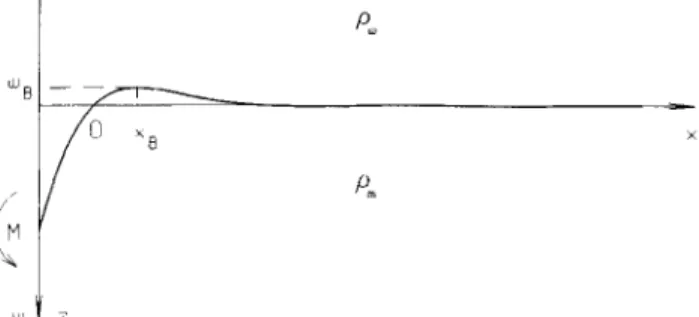
LFigure 4. Mechanical model o f the suhducting plate:
bending moment M-positive counterclockwise;
z-axis, deflection w-positive downward, w,-the outer-rise height; x-axis-positive oceanward, w(xB) = wB;
sea-water density p w < mantle-rock density pm.
We select thc coordinate-axes start point so that wl,-,,= 0. It is treated as the 'zero point': at the trench axis I < 0. at the outer rise
.Y > 0.
where
M
is the flexural moment (counterclockwise positive), x is horizontal coordinate, positive oceanward, pm and pw are densities of the upper mantle rock and of the sea water (we later used pm - pw = 2.30. 103 kg m-')), g = 9.8 m s-' is gravity acceleration, and w is vertical deflection of the plate. Eq. (4) is valid for any kind of rheology. In our case we deduce the non-linear ordinary differential equation in the complete form.We do not allow any total compressive or tensile force
along the plate, so we define 'the bending stress' as
A+,
z )
= a&,z )
- m Z z ( x ,z ) .
It is well known for the elastic layer (Turcotte & Schubert 1982) that( Z - z o ) E d 2 w ( x )
1 - V' dx2
Au(x, Z ) = ___ ~
where
z
is depth counted down from the top of thelithosphere,
zo
is depth to the neutral plane, E is Young's modulus, and v is Poisson's ratio. In the elastic layer we set E = 7.
10'" Pa and v = 0.25. From(9,
the bending moment for the purely elastic layer isd 2 w ( x ) ETf
M ( x ) = D ~ with D =
dx2 12( 1 - v2)
where D is rigidity, and T, is thickness of the elastic layer.
Substitution of (6) in (4) gives a linear differential equation. Its solution is
w ( x ) = e-"/"[C, cos @ / A )
+
C, sin ( x / A ) ]+
eX'"[C3 cos ( x / A )+
C4 sin ( x l h ) ] (7)where A = [40(pm - p w ) - ' g-1]"4 is the flexural parameter; C,, C,, C,, C, are constants defined from boundary conditions, as a rule C, = C, = 0 to prevent any exponential growth of the solution (7) at x + m. By selecting the starting
point of the horizontal coordinate, another constant is
excluded, for instance, w ( x ) = C,e-"/" sin ( x l h ) .
The vertical gradient of stress in the elastic layer as derived from (5) is
~ A & , z ) - E d 2 w ( x ) y ( x ) = az
1 - y2 dx2 '
The eq. (4) is written assuming that thickness of the plate is neglible as compared to the flexure radius. Thus we have a
at INIST-CNRS on August 23, 2016
http://gji.oxfordjournals.org/
physical restriction for (8) in our approach:
E d 2 w ( x ) 7-10"'Pa
1 - v
1
dx'1
<< 1-
0.25' 'I y / = y _ _
= 0.8 MPa m-'.
It is also possible to show that this restriction prohibits considering cases in which the intermediate elastic layer between the brittle and ductile zones somewhere is less than about 3 km.
In addition we assume also that the upper and lower bounds of the intermediate elastic layer lie respectively in the brittle and ductile portions of the YSE. If the plate is
convex upward, the last condition is always satisfied due to
I Y B C ~
> ~ ' Y B T ~ and Y D C = -YDT < YBT < 0 (see Appendices and results of computations of yL in Fig. 2). If the plate is convex downward, it is possible to show that the condition may be violated only by very strong flexure of the plate edge upward: it requires a 5 km elevation of the relief in a 100 km horizontal distance due to the downward-convex plate flexure only. Such flexure does not seem to occur in nature. Using notations T,,zB,
zD,
andzn
of Fig. 1, and assuming zero horizontal external force, we getZB = _ _ yzo and
z,,
=that allows us to deduce
[lr"lAv(x,
z ) d z
=1)
YZO - Y D L Y - YO Y - Y D Z d Y ) Z d Y ) ZYB dz + (Z - z n ) y d z % S ( Y ) I'm +( z
- Tm)?Dd z
z D ( Y ) (9) where y e and y,, denote either y B c and yDT, or yBT andyDc. We consider yB and yD as independent from
z
and later also from x. This assumption for upper brittle layers ofthe lithosphere is a consequence of our model. As
concerning lower ductile layers, y u depends on strain rate that changes along the plate and probably with depth. The lower ductile layers represent a relatively thin part of the lithosphere so that vertical distribution of strain rate there seems to be quasi-constant (obviously we can neglect changes substantially less than an order of magnitude of strain rate). A relative distribution of strain rate along a
subducting plate perpendicular to the trench was obtained by Chapple & Forsyth (1979). In particular, a pronounced
peak of strain rate was shown close to the trench. According
to estimations cited above, far from the trench the strain rate is less about two or three orders of magnitude that diminishes YSE, but plate curvature, bending stresses and
moment vanish much faster. In addition, far from the trench radius of plate curvature is very large so that it is comparable with the radius of the earth and we cannot consider so fine effects in our plane 2-D model. Thus in our approach it seems to be natural to treat YSE as constant.
From (9) we have immediately
Z O t Y ( X ) l = (10)
Y D Y B - Y
Influence
of rheological parameters 21 3(11)
It follows from (10) and (11) that at infinitesimal flexure lim
zO(
y ) = Tn,/2,7-0 Y+O
and
lim M ( y ) = 0,
lim M ( y ) / y = T;/12
so that, as compared to (6) and (8), the plate behaves like it
is purely elastic. On the other hand, for the upward convex
plate (10) gives
y - 0
y-+C= lim z O ( Y ) =
TmI(1
+V'GZG)~
y-+.Q lim M ( y ) = -YBTTi/[6(1 + '/YBThDC)I
i.e. the permissible bending moment is substantially limited (restrictions do also exist for the downward convex one but may not be reached in fact). We note that the so-called effective rigidity was used by many authors (e.g. Bodine et
al. 1981; McAdoo et al. 1985; Chamot-Rooke & Le Pichon 1989). Similar to (6) and using ( 8 ) it can be defined as
Dcff( y ) = M ( y ) E / [ ( 1 - Y') y ] . Obviously it depends on y,
i.e. on x , so that its using in (4) requires to take into account also its derivatives.
We do not deal with the effective rigidity, but deduce directly derivatives of the bending moment to present eq. (4) in the complete form for our rheology. Implying that
Y'E--- d y ( x ) we note:
dx '
at INIST-CNRS on August 23, 2016
http://gji.oxfordjournals.org/
214 A . N . Panteleyev and M . Diarnent with zO from (10). Further,
where
Finally we define another function: B(.r) =
E w ( x ) / ( l - v'), We get by substituting (13) in ( 4 ) and keeping in mind that
p " =
y :where F and F' are defined in (12) and (13). We obtain a n essentially non-linear differential equation of the fourth order.
For the fourth-order eq. (14) the boundary problem
requires four boundary conditions. We showed that the plate at infinitesimal flexure appears t o be purely elastic. It
Trench
I
1 B R I T l l - F
SLIDING,
is obvious that the solution must be bounded a t x - + m , but there is n o general solution in the complete form for the non-linear eq. (14) to put C, = C, = 0 similar to (7).
Nevertheless we can represent the same conditions in a different form. By differentiating (7) for three times we obtain a system of four linear equations. I t is easy t o show that C , - C', = 0 is equivalent to
d w ( x ) + -
'
A
d 2 w ( x ) ~-W ( X ) + A ___ - 0
c
dx 2 dx'taken at any point of the purely elastic plate. For our plate these conditions should be assigned to some far point such that .r/A >> 1 where A may be defined analogous to (7). The position of the point is to be controlled during the numerical solution so that results of computations would remain stable.
Two other conditions can be assigned from measurements
near the trench:
W ' ( X , ) = w,
w ' ( r,) = w,'
For instance, at the crest o f the outer rise w, equals its height
w B (Fig. 41, and w,'= 0.
It is easy to see that eq. (4) in form (14) can be solved by the Runge-Kutta procedure. We used such fourth-order
procedure within the framework of a multiple-shooting
algorithm. The shooting was realized from the purely elastic solution derived analytically to the solution of the non-linear problem by step-by-step increase in the non-linearity of the problem.
RESULTS O F MODELLING
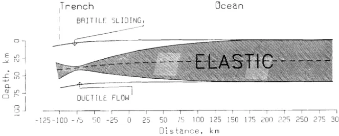
A family of numerical solutions has been built that describes the flexure of the oceanic lithosphere at subduction zones. Fig. 5 shows a n example from the family. T h e oceanic part behaves purely elastically since it is not flexed and Amr is not reached. Substantial changes in thickness of brittle, ductile
Ocean
I
DLICT IL €
FLOW 1J '3 J I I I r- I 1 I I I 1 I 1 I -1-125-100
- 1 ' 350 -25 0
25
50 15 100125 150 175 20C
225250 275 300
Distance, k mFigure 5. A computed structure ot a 100Ma old oceanic l i t h a p h e r e exposed to the lower-lithosphere strain rate of 10 ' f l s - ' . which means
T,,, = 60 krn (an example from the family of solutions. see text). An outer rise crest as high as 1wBl = 323 m is located at a distance of xI3 = 84 km
to the right from the ' i e r o point' (see Fig. 4). T h e most intcnsc flexure (corresponding to the minimal thickness of the intermediate elastic layer) is obtaincd ;it a distance of lxI,l = 74 km to the Icft from the 'zero point'. A dashed line inside o f the elastic layer shows the neutral plane.
at INIST-CNRS on August 23, 2016
http://gji.oxfordjournals.org/
and intermediate elastic layers are observed. T h e intermedi- ate elastic layer has a pronounced thickness minimum. As is well known (e.g. Watts & Talwani 1974) the flexure induced by the subduction results in a n outer rise bulge. It is too small to be observed in Fig. 5 simply because of the uniform vertical and horizontal scales.
Figure 6 shows that for a given set of activation energies,
age and strain rate, our model can produce various
outer-rise heights and oceanic slopes in the trench while the bulge length remains nearly constant. O n e would think slope observations in addition t o outer rise height data are necessary to deduce T,. Nevertheless, it would be useful only for a relatively weak flexure, for instance, at seamounts. Oceanic slopes in trenches are steep so that strong flexure may only give rise t o them. 'Strong flexure' means that the bending moment is close to being saturated, the intermediate elastic layer is almost degenerated and the outer-rise height reaches its maximum. In fact the outer rise height of YO per cent of its maximum makes the slope as steep as 4" only. O n the other hand, a l m increase of the outer rise crest at strong flexure makes the intermediate elastic layer 0.4 km thinner with sharp steepening of the slope. Thus the lithosphere flexure model for subduction zones should imply outer-rise heights not less than about YY
per cent of their maximal allowed values.
The computations have shown that (and how) the height (Fig, 7) and the location (Fig. 8) of the outer-rise crest, the respective free-air gravity anomaly (Fig. 9) as well as the
location of the most intense flexure of the oceanic
lithosphere (Figs 10 and 11) depend o n the lithospheric age and the lithosphere strain rate, and hence o n activation energies in the manner discussed above. We note that the most intense flexure area whose location is prescribed by
Figs 10 and 11 should contain extremely high vertical
gradient of difference of the principle stresses so that it may be very active seismically.
A gravity effect of a flexed lithospheric plate was
computed by Parker's algorithm (Parker 1972) which is very
Distance, km
-fi0 0 6 0 120 180 740 300 360 4 2 0
"1
To.kO 0 60 120 180 240 300 360 4Zd
D ~ s t a n c e , k m
Figure 6. Outer-rise topography of 90 Ma old lithosphere exposed
to the lower-lithosphere strain rate of 10 ' " 5 : I , which means T', = 57 km. Solutions for the outer-rise crest heights lwH( of 400m. 360111, and 320m (99 per cent, 89 per cent and 79 per cent of the maximal permissible height respectively) are shown. Coordinate axes correspond 10 Figs 4 and 5. T h e vertical scale is 150 times greater than the horizontal one. T h e zero level is shown.
Influence of rheological parameters 21 5
F
Log10 I S t r a i n R a t e r s )
Figure 7. Maximal allowed outer-rise height Iw131, m, as a function of the strain ratc P : log,,,[i.(s I ) . s], horizontal axis, and the lithospheric age, Ma, vertical axis.
fast. Unlike geoid, free-air gravity anomalies a r e almost insensitive t o the way of modelling of the continental slope of the trench. At the same time this algorithm is stable even if steep slopes in trenches are present. In such cases it is sufficient t o take into account additional terms of expansion (usually up to 8). The number of terms was determined by
comparison with the method of Talwani. Worzel &
Landisman (1959). Computations were made for an oceanic
lithosphere composed of three layers (crust sedimentary
rocks and basalts, then upper mantle rocks) of different
Log10 f S t r a i n R a t e * s l 6 1 9 -18 - 1 7 -16 -15 - 1 4 - 1 % 'D
~
-
~
-
~
\
-
-
-
-
~
-
~
-o m o x-
g & U 0 coe
0 0 m 3 =r 0 - 1 9 -1s -17 -16 -15 1 4 - I ? Log10 IStrainRa t e * s lFigure 8. Outer-rise crest location (to the right from the 'zero point', see Fig. 4) x H , km, as a function of the strain rate 6:
logl,,[&(s-') . sJ. horizontal axis, and the lithospheric age, Ma, vertical axis.
at INIST-CNRS on August 23, 2016
http://gji.oxfordjournals.org/
216 A . N . Panteleyev and M . Diament
. - ..
L o g 10 I S t r a i nRa t e*s1
Figure 9. Maximal free-air gravity anomaly over thc outer-rise AKn. mGal, a s a function of thc lithosphcric age, Ma, vertical axis. and the strain rate F: log,,, [ E ( s I) . s], horizontal axis.
densities. We assume density contrasts to b e 1 5 0 0 k g K '
(sea water-crust sedimentary rocks) at the depth o f 5 km beneath the ocean surface, 300 kg m p 3 (sedimentary rocks-basalts) at the depth o f 1 km beneath the ocean floor, a n d 500 kg m -3 (crust-mantle) at the depth of 7 km
beneath the ocean floor.
Figures 7-11 also show that flexure of the young
lithosphere, less than about 70 Ma, is mainly controlled by the age, while for the flexure of the older lithosphere, more than 100 Ma particularly, the strain rate is more significant. This result for a n ancient lithosphere is illustrated in Fig. 12.
LoglO I S t r a i n R a t e r s l
6 1 9 -18 -17 -16 -15 - 1 4 ~
2
,--T--T;i
\
\
\
-19 -18 -17 -16 -15 - 1 4 -I3
Figure 10. Location of the most intense flexure of the oceanic
lithosphere (to the left from the 'zero point', see Fig. 4) IxF,J, km, as a function of the strain rate C: log,,, [ F (s I) . s ] , horizontal axis, and
the lithospheric age, Ma, vertical axis. Log1 0 I5 i r a i n R a + e * s I LoglO I S t r a i n R a t e x s l 0 0 0 m 0 N -19 -18 -17 -16 -15 - 1 4 -13 Log10 I S t r a i n R a t e x s l
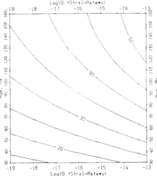
Figure 11. Domain depth beneath the sea-surface z,,, krn, of the
minimal thickness of the intermediate elastic layer (at the most intense flexure area) as a function of the lithospheric age, Ma, vertical axis, and the strain rate F: log,, [C(s-') . s], horizontal axis.
Distance. k m -80 0 80 160 240 320 400 480 I _-, 0
z
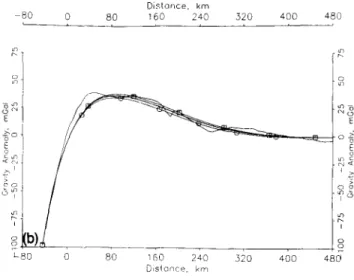
L a @ 0 80 160 240 320 400 480 Disiance, kmFigure 12. Superposed frce-air gravity-anomaly profiles. Broken
curve: interpolated shipboard data across the Kuril trench (100 Ma old lithosphere) along an orthodromic line from the point 45"N, 151"E by the initial azimuth 142".
Middle line: a model profile (lithospheric age l00Ma, strain rate
s , hence T,, h 0 k m ) selected by minimization of rms deflections from the shipboard data profile.
T w o pairs of model profiles arc shown (thin lines) to demonstrate the influence of thc swain rate and age variations:
(a) (the lower line) lithospheric age l 0 0 M a , strain rates 10 - I X spl and s p l (the upper line);
(b) (the lower line) strain rate 10 " S I,
lithospheric age 90 M a and 110 Ma (the upper line). T h e horizontal coordinate axes correspond to Figs 4 and 5.
1" I 6 ~I
at INIST-CNRS on August 23, 2016
http://gji.oxfordjournals.org/
Influence of rheological parameters 21 7
Dlsiance, km
-80 0 8 0 160 2 4 0 320 400 2 0
I,
Figure 12. (C'onrinwd.)
Therefore, if the age of an ancient subducting lithosphere is
reasonably well known, i.e. with an accuracy of about
lOMa, the modelling of flexure allows estimation of the in
situ strain rate in the lower lithosphere assuming values of
activation energies. Conversely, if the strain rate is known (for instance, from subduction velocity data) it is possible t o evaluate activation energies using lithospheric age data. Determination of joint influence of strain rate and activation energies on flexure of the young lithosphere requires precise knowledge of its age.
C O M P A R I S O N WITH D A T A
Using developed theory we analysed data across the Kuril trench where the subducting lithosphere presents age about the border between the Upper and the Lower Cretaceous, i.e. 100Ma ranging between 9 0 M a and 110Ma (Nikolayev 1988) that is nearly constant along the trench. In addition, this area does not contain too many seamounts, ridges or
fracture zones so that the analysis can be made using a large set of unperturbed profiles. Moreover, the trench is straight and long, whilst both changes in the trench direction and trench junctions disturb the outer rise geometry (Deplus &
Dubois 1989). Finally we note that an estimate of strain rate, averaged over the lithospheric thickness, was given for the Kuril trench by McNutt & Menard (1982) using a quite different approach. Thus the Kuril trench appears t o b e a good test for our model.
T h e model may be applied t o interpret both gravity and bathymetry data. As it was already discussed (e.g. Watts &
Talwani 1974) results obtained using gravity profiles are more reliable, since shipboard marine gravity data naturally filter the short-wavelength noise that can be present in bathymetry. Furthermore, and more importantly, the gravity profiles are less affected by the sedimentary cover. The presence of sediments can result in a bathymetry that does not represent the flexure of the lithosphere. In addition, flexure is also visible in satellite altimetry (McAdoo &
Martin 1984) so that abundant satellite altimeter data allow
us to make a complete regional analysis by the same
method.
In the present study, we used gravity profiles supplied by
Figure 13. The Kurd trench area. North latitude and east longitude
in degrees a r e noted o n the border of the coordinate grid. The location of selected data profiles is shown.
the Bureau GravimCtrique International. 12 orthodromic
profiles, 800 km long, were constructed by interpolation from all randomly distributed data points available in the area. The profiles were taken perpendicular t o the trench (Fig. 13). T h e spacing along each profile is 7 km. Note that
special care was taken t o accomplish interpolations only in areas with sufficiently dense coverage of data and t o avoid
Log10 ( S t r a i n R o t e
*
s ) -19 -18 - 1 7 -16 -15 - 1 4 -13Cr
O / i : :9
--19 --I8 -17 - 1 6 -15 - 1 4 - 1 3 - Log10 ( S t r a i n R a t e*
s )Figure 14. Averaged relative rms misfits between gravity data and
model profilcs. Since frcc-air gravity anomaly rms deviations between data and model profiles have a marked range difference because of diverse roughness of data profiles, we normalized rms misfits for each profile to the respective minimal value. Then relative rms misfits have been averaged through all the profiles. A pronounced minimal rms misfit (vertical axis) at the strain rate
{F: log,,,[S(s ' ) ' s ] , horizontal axis} of about 3.10 " S
'
isobserved.
at INIST-CNRS on August 23, 2016
http://gji.oxfordjournals.org/
218 A . N . Panteleyev and
M .
Diamentt h e junctions with Aleutian and Japanese trenches as well as seamounts, ridges and fracture zones.
The modelling of profiles was achieved assuming an age of 100Ma and varying the strain rate that can represent, as it was shown above, variations of activation energies. The estimated strain rate lies between 10-"s-' and s - '
assuming usual Q, = 536 kJ/mole and Q , = 523 kJ/mole
(Fig. 14). O n the basis of a relationship between strain rate in the oceanic lithosphere, outer-rise geometry and subduction rate derived from the purely elastic model, McNutt & Menard (1082) evaluated strain rate for several
trenches; in particular, for the Kuril trench
t- = 1.4. 10p'hs--
'
that is consistent with our results. Hence t h e values of activation energies used seem to be reasonable. Note that our model does not use any information about subduction rate. Taking into account the lithospheric age range mentioned above as well as uncertainty of strain rate, according t o Figs 3(a) and 7-11, we obtain on the wholetrench approximately: T , =
z b =
61 & 3 km,I w , ~
= 435 f 30 m, AgB = 38 f 3 mGal,l ~ ~ l =
75 f 4 km,lzHl
= 45 f 3 km. Finally, from Table 1 ,temperature at depth
zh
is about 750 f 20 "C. x , = 86 f 4 km,CONCLUSIONS
W e developed a model of flexure of the oceanic lithosphere assuming a realistic rheology in order to estimate the strain rate of the lower oceanic lithosphere.
The mechanical lithosphere thickness appears to be controlled not only by the age, i.e. by the temperature distribution, but also by the strain rate and creep activation energy in the lower lithosphere. We computed flexure of the oceanic lithosphere at subduction zones for lithospheric ages ranging from 30Ma to 160 Ma and strain rates from
10-l9 s-l up to 1 0 - 1 ~ s-* at activation energies
Q, = 536 kJ/mole and Q, = 523 kJ/mole. Analysis of the trade-offs among thermal structure represented as litho- spheric age, activation energies, and strain rates allows us to extend the results of o u r modelling to consider different activation energy values.
Tests of the model show that from observations of flexure it is possible to estimate either the in situ strain rate or the in situ activation energies or the lithospheric age if other of these parameters are known. The accuracy of such
estimation is better for old lithosphere. For young
lithosphere (70Ma or less), a precise knowledge of age is
crucial. Use of independent estimations of strain rate,
activation energies, and age based on different approaches improves the accuracy of rheology parameter evaluations. In this case a best-fit set of rheology parameters can be obtained.
ACKNOWLEDGMENTS
W e are indebted to G. Balmino for the supply of gravity data and computer time. We thank G. Balma and M. Sarrailh as well as A. Cazenave and K. Dominh for providing sea gravity and some Geosat altimeter data. We thank M. G. Kogan for numerous helpful discussions. We appreciated the comments of two anonymous reviewers.
REFERENCES
Bodine, J. H., Steckler, M. S. & Watts, A. B., 1981. Observations of flexure and the rheology of the oceanic lithosphere, J . geophys. Res., 86, 3695-3707.
Bodine, J. H. & Watts, A. B., 1979. Lithospheric flexure seaward of the Bonin and Mariana trenches, Earth planet. Sci. Lett., 43, 132-148.
Brace, W. F. & Kohlstedt, D. L., 1980. Limits on lithospheric stress imposed by laboratory experiments, J . geophys. Res., 85, Byerlee, J., 1978. Friction of rocks, Pure & uppl. Geophys., 116,
615-626.
Caldwell, J. G., Haxby, W. F., Karig, D. E. & Turcotte, D. L., 1976. On the applicability of a universal elastic trench profile, Earth planet. Sci. Lett. ~ 31, 239-246.
Cazenave, A,, 1984. Two distinct trends for cooling of the oceanic lithosphere, Nature, 310,401-403.
Chamot-Rooke, N. & Le Pichon, X., 1989. Zenisu Ridge: mechanical model of formation, Tectonophysics, 160, 175-193. Chapple, W. M. & Forsyth, D. W., 1979. Earthquakes and bending
of plates at trenches, J. geophys. Res., 84, 6729-6749.
De Bremaecker, J. C., 1977. Is the oceanic lithosphere elastic or viscous, J. geophys. Res., 82, 2001-2004.
Denlinger, R. P., 1992. A revised estimate for the temperature structure of the oceanic lithosphere, J . geophys. Res., 97, Deplus, Ch., 1987. Comportement mecanique de la lithosphkre
ocCanique, cas d'une subduction complexe, PhD thesis. Universite Paris-Sud.
Dcplus, Ch. & Dubois, J., 1989. Flexural response of thc oceanic lithosphere at an arc-arc junction: implication for the subduction of aseismic ridges, Tectonophysics, 160, 63-73. Fadaie, K. & Ranalli, G., 1990. Rheology of the lithosphere in the
East African rift system, Geophys. J . Int., 102, 445-453. Goetze, C. & Evans, B., 1979. Stress and temperature in the
bending lithosphere as constrained by experimental rock mechanics, Geophys. J . R. astr. Soc., 59, 463-478.
Gunn, R., 1943. A quantitative study of isobaric equilibrium and gravity anomalies in the Hawaiian islands, J . Franklin. Inst., Hanks, T. C., 1971. The Kuril Trench-Hokkaido Rise system: large shallow earthquakes and simple models of deformation, Geophys. J . R. astr. Soc., 23, 173-189.
Ivanov, S. S., 1989. Stresses in an oceanic lithosphere associated with its curvature changes during its cooling, Rep USSR Acad. Sci., 309, 4, 838-841 (in Russian).
Kirby, S. H., 1977. State of stress in the lithosphere: inferences from the flow laws of olivine, Pure appl. Geophys., 115, 245-258. Kirby, S. H., 1983. Rheology of the lithosphere, Rev. Geophys.
Space Phys., 21, 1458-1487.
Kirby, S. H. & Kronenberg, A. K., 1987. Rheology of the lithosphere: selected topics, Rev. Geophys. Space Phys., 25, 1219-1244.
Lobkovsky, L. I. & Sorokhtin. 0. G., 1976. Plastic deformations of the lithosphere at a subduction zone, in Tectonics of Lithospheric Plates, pp. 22-52. Ed. Sorokhtin, 0. G., IOAN, Moscow (in Russian).
McAdoo, D. C., Caldwell, J. G. & Turcotte, D. L., 1978. On the elastic-perfectly plastic bending of the lithosphere under generalized loading with application to the Kuril trench, Geophys. J . R. astr. Soc., 54, 11 -26.
McAdoo, D. C. & Martin, C. F., 1984. Seasat observations of lithospheric flexure seaward of trenches, J . geophys. Res., 89, McAdoo, D. C., Martin, C. F. & Poulouse, S., 1985. Seasat observations of flexure: evidence for a strong lithosphere,
Tectonophysics, 116, 209-222.
McNutt, M. K. & Menard, H. W., 1982. Constraints on yield 6248-6252. 7219-7222. 236,373-390. 3201-3210. at INIST-CNRS on August 23, 2016 http://gji.oxfordjournals.org/ Downloaded from
Influence of rheological parameters 219
strength in the oceanic lithosphere derived from observations of flexure, Geophys. J . R. astr. Soc., 71,363-394.
Melosh, H. J., 1978. Dynamic support of the outer rise, Geophys. Res. Lett., 5 , 321-324.
Nikolayev, N. I., 1988. The Newest Tectonics and Geodynamics of the Lithosphere, Nedra, Moscow (in Russian).
Parker, R. L., 1972. The rapid calculation of potential anomalies, Geophys. J . R. astr. Soc., 31,447-455.
Parker, R. L. & Oldenburg, D. W., 1973. Thermal model of ocean ridges, Nature, 242, 122, 137-139.
Parsons, B. & Molnar, P., 1976. The origin of outer topographic rises associated with trenches, Geophys. J . R. astr. SOC., 45,
Parsons, B. & Sclater, J . G., 1977. An analysis of the variation of
ocean floor bathymetry with age, J . geophys. Res., 82,803-827. Ranalli, G. & Murphy, D. C., 1987. Rheological stratification of the
lithosphere, Tectonophysics, 132,281-295.
Stein, C. A. & Stein, S., 1992. A model for the global variation in oceanic depth and heat flow with lithospheric age, Nature, 359, Talwani, M., Worzel, J. L. & Landisman, M., 1959. Rapid gravity computations for two-dimensional bodies with applications to the Mendocino submarine fracture zone, 1. genphys. Res., 64, 49-59.
Turcotte, D. L., McAdoo, D. C. & Caldwell, J. G., 1978. An elastic-perfectly plastic analysis of the bending of the lithosphere at a trench, Tectonophysics, 47, 193-205.
Turcotte, D. L. & Oxburgh, E. R., 1967. Finite amplitude convective cells and continental drift, J . Fluid Mech., 28,29-42. Turcotte, D. L. & Schubert, G., 1982. Geodynamics applications of
continuum physics to geological problems, John Wiley & Sons, New York.
Vening-Meinesz, F. A., 1941. Gravity over the Hawaiian Archipelago and over the Madeira Area: conclusions about the Earth' crust. Proc. Kon. Ned. Akad. Wetensch., 44, 1-12. Watts, A. B. & Talwani, M., 1974. Gravity anomalies seaward of
deep-sea trenches and their tectonic implications, Geophys. J . R. astr. Soc., 36, 57-90.
707-712.
123-129.
A P P E N D I X A
The highest permissible difference of the principle stresses in the upper oceanic lithosphere (brittle layers)
We call normal, tangent and principle stresses as un, u, and u3 s u2 s u1 respectively. For the plane area parallel to the direction of u2 and making an angle a between its normal and the direction of v l , the Mohr's external circle relationship gives (e.g. Turcotte & Schubert 1982):
q 1 - f f 3 .
cos2a; u,=- sin 2a.
U l + U 3 f l 1 - 0 3
un=-+-
2 2 2
('41)
Byerlee's laws [see eq. (1) above] can be represented in the general form as 7 = A u n + B . It means u,= 7 if the difference of the principle stresses reaches its highest permissible value humax = (ul - u ~ ) , ~ , at given u1 or u3.
Using (1) and ( A l ) it can be written as
(sin 2 a - A - A cos 2 a ) u , = (sin 2 0 + A - A cos 2a)u,
+
2B.( '4.2) On the other hand, ( A l ) gives u: = -(un - u3)(un - ul).
By differentiation at A a m a x and taking into account
d r l d u , = A , we find:
2/47 = -(un - a , ) - (un - ~ j= )uI
+
u3 - 2an. ('43)A substitution of ( A l ) taken at Aumax for (A3) gives A = -ctg 2a. Because sin 2 a
*
0, we have sin 2 a =(1 +A2)-''' and cos 2a = -A(1 +A2)-'12 so that (A2) can be rewritten as
[(I
+
A2)'12 - A ] u , = [(l+
+
A]u,+
2B. ('44)Let us consider the elastic stress that is supported by the plate until AumaX is reached. We assume that only lithostatic
initial stress exists in the plate from its formation time. Generally the plate is deformed as long as it moves away from the mid-ocean ridge and even changes the sign of its curvature (Ivanov 1989), but stress must relax with time. In addition a specific cooling regime is observed for the oceanic lithosphere younger than 30 Ma (Cazenave 1984). Since we examine the plate older than 30Ma, we shall not consider
these features. We write for the non-deformed plate:
uXx = uyv = u,, = u , = u2 = u3 = p where p is the lithostatic pressure. According to Hooke's law, we get
EE,, = uX, - vuYy - VU,, = ( 1 - 2v)p
[
EE,, = - VU,, - Y a y y+
uZz = (1 - 2v)pEEyy = - vu,,
+
uyy - vu,, = ( I - 2v)p. (A5)If there is an additional stress Aux, = Au, but deformation remains in the x-z plane, i.e. = 0, then the new stress
and deformation are CXx = p + A u , 8,, = p , and
E y y = (1 - 2v)p/E. Together with (A5), this results in Ed,, = p
+
A a -yeyy
- vp (1 - 2 ~ ) p = - V ( P + A C T )+
5, - VP Ed,, = - Y ( P + A m )-
VI?,,~ + p hence 6, - u , ~ =A U
8, - u , , ~ = V A U .{
G,, - u,, = 0Poisson's ratio for rocks is restricted as 0.03 < v ~ 0 . 4 (Turcotte & Schubert 1982). Therefore the principle stresses become u 1 = a,, = p
+
A u u2 = a y y = p+
VAU if Am > O ,1
u3 = uz, = p and u1= a,: = p ~ ~ , = ~ ~ , , = p - v I h u l i f A a s O . u 3 = u.<, = p - IAFlWe note that the pressure has changed:
P
= ( a ,+
u2+
u3)/3 = p+
(1+
v)Au/3.We define the signed A a m a x that delimits the YSE as
so that A a , > O for compression and A u , < O for tension.
Substituting (A6) in (A4), we have
[A
+
( 1+
A 2 ) ' / 2 ] for compression. [A - (1+
for tension. ('48) A u r = 2(Ap + B ) at INIST-CNRS on August 23, 2016 http://gji.oxfordjournals.org/ Downloaded from220
Taking i n t o account that d p l d z = pg, the following relation holds for each layer where A, B and p are constant:
A . N . Panteleyev and M . Diament
%_=
{yBc] = 2 A p g { [ A+
(1+
A2)’/’] for compression.dz Ywr [ A - (1
+
A2)1/2] for tension.( A 9 Note that actual values of A give yBc/ yBT = - ( 4 rt 1).
At last we can determine the dependence of A c r on depth keeping in mind the continuity between ( l a ) and ( l b ) at un = 0.2 G P a . The greatest Mohr’s circle fitting both ( l a ) and ( l b ) may be derived from (A4). It corresponds t o
a I = 530 MPa and a3 = 113 MPa with respective A c m a x = 417 MPa. Substituting in (A8) for A and B their values f r o m ( l ) , we find A u , = 3 . 6 9 ~ a t O s p s 1 1 3 M P a 2 . 1 2 ~
+
177 MPa at p > 113 MPa (AlOa)i
i
for compression. - 0 . 7 8 7 ~ at 0 s p s 530 MPa - 0 . 6 8 ~ - 57 MPa at p > 530 MPa (AlOb)Taking into account loading of the roughly 5 km deep
he, = for tension. ocean, w e get p,z at 0 s z s
T,
p,T,+
p,(z - T,) at z ( A l l ) p( z )
= 0.05 GPa+
gwhere
z
is the depth below the mean ocean-floor level, g is gravity acceleration, p E is oceanic crust density, p, is upper mantle density, T, is oceanic crust thickness. Substitutingp, = 2.8
.
lo3 kg m-3, = 6 km,g = 9.8 m sC2, we find p = 113 MPa a t z
--
2.3 km in the crust and p = 530 MPa at z = 15.7 km in the upper mantle. Thus shear stress in the tensional regime follows ( l a ) down t oz --
16 km, while for compression, shear stress is mainly (below z = 2.3 km) represented by (lb). Finally substituting( A l l ) in (A10) we have pm = 3.3
. 10’
kg m-3, 185+
101z
MPa a t 0 283+
582 MPa a t 2.3 S z s 6 km 223+
68z MPa a t z > 6 k m -38-222 MPa at 0 S z s 6 km - 17 - 2 5 . 4 ~ MPa at 6 s z -71 - 22z MPa atz
> 15.7 kmfor compression and tension respectively (see Fig. 1).
z < 2.3 km
(A12a)
15.7 km (A12b)
A P P E N D I X B Notation list
YSE-yield stress envelope;
A , B-general coefficients of Byerlee’s laws: 7 = A o ,
+
B ;a-thermal plate thickness; C-local constants in formulae; D-rigidi ty;
E-Young’s modulus;
g-gravity acceleration;
k-thermal diffusivity;
M-the bending moment;
OX-horizontal coordinate axis, perpendicular to the
trench, oceanward positive;
OY-horizontal coordinate axis, parallel to the trench;
OZ-vertical coordinate axis, downward positive;
P-pressure: p-lithostatic pressure; Q-activation energy; R-gas constant; T-temperature; T,-zero-age temperature; T,-oceanic-crust thickness; T,-thickness of the elastic layer
K,,-thickncss o f the mechanical lithosphere; [-time (age);
w-vertical deflection of the plate;
w,-outer-rise height (taken as a negative value); XI,-horizontal coordinate of the outer-rise crest;
x,,-horizontal coordinate of the most intense flexure of the z-depth below the mean ocean-floor level;
z,,-neutral-plane depth below the mean ocean-floor level;
z,-depth (below the mean ocean-floor level) of the upper level o f the elastic layer between elastic and brittle ones;
z,-depth (below the mean ocean-floor level) of the lower level of the elastic layer between elastic and ductile ones;
z,,-depth (below the mean ocean-floor level) o f the base of
the mechanical lithosphere;
zlI-domain depth (below sea-level) of the minimal
thickness of the elastic layer;
a-angle between the normal to the plane area and the
direction of the greatest principle stress a l ;
y H , y,,-either ye<- and yLTr, or Y ~and ~ yoc; - ~
y,,r-vertical gradient of A u r at compression in brittle y,,vertical gradient of A u r at tension in brittle layers; y,-absolute value of the vertical gradient of
ACT^
in lower y,,,.-vertical gradient of A c r at compression in ductile y,,-vertical gradient of ha, a t tension in ductile layers;Ag,-maximal, free-air gravity anomaly over the outer rise;
Ac-additional stress, compressive positive;
Ac,,,,-highest permissible difference of the principle
Am,-signed highest permissible (restrictive) difference of
c-deformations (with respective indices); &-strain rate:
A-flexural parameter;
v-Poisson’s ratio; p-density;
p,-oceanic-crust density; p,,--upper mantle density;
p,-sea-water density;
a,,-a local constant in the creep law (2a);
a3 s a2 s a,-the principle stresses, compressive positive;
c,-normal (confining) stress, compressive positive:
a,-tangent (breaking) stress, compressive positive:
u.,,-normal stress along the OX-axis, compressive positive;
a,,-normal stress along the OY-axis, compressive positive;
a,,-normal stress along the OZ-axis, compressive positive;
r-highest permissible tangent (shear breaking) stress. lithosphere;
layers;
ductile layers: yr. = IyITrl = Iync.l;
layers;
stresses: ACT,,,,, = ( a , - u ~ ) , , , , ~ ;
the principle stresses: A a r = AcmSlx sign ( P - p ) ;
at INIST-CNRS on August 23, 2016
http://gji.oxfordjournals.org/