HAL Id: cea-01377130
https://hal-cea.archives-ouvertes.fr/cea-01377130
Submitted on 6 Oct 2016
HAL is a multi-disciplinary open access
archive for the deposit and dissemination of
sci-entific research documents, whether they are
pub-lished or not. The documents may come from
teaching and research institutions in France or
abroad, or from public or private research centers.
L’archive ouverte pluridisciplinaire HAL, est
destinée au dépôt et à la diffusion de documents
scientifiques de niveau recherche, publiés ou non,
émanant des établissements d’enseignement et de
recherche français ou étrangers, des laboratoires
publics ou privés.
Measurement of the intrinsic damping constant in
individual nanodisks of Y3Fe5O12 and Y3Fe5O12|Pt
C. Hahn, V. Naletov, G. de Loubens, O. Klein, O. d’Allivy Kelly, A. Anane,
R. Bernard, E. Jacquet, P. Bortolotti, V. Cros, et al.
To cite this version:
C. Hahn, V. Naletov, G. de Loubens, O. Klein, O. d’Allivy Kelly, et al.. Measurement of the intrinsic
damping constant in individual nanodisks of Y3Fe5O12 and Y3Fe5O12|Pt. Applied Physics Letters,
American Institute of Physics, 2014, 104 (15), pp.152410. �10.1063/1.4871516�. �cea-01377130�
YIG and YIG|Pt
C. Hahn,1V.V. Naletov,1, 2, 3G. de Loubens,1 O. Klein,1O. d’Allivy Kelly,2 A. Anane,2R. Bernard,2E. Jacquet,2
P. Bortolotti,2V. Cros,2 J.L. Prieto,4and M. Mu˜noz5
1)Service de Physique de l’ ´Etat Condens´e (CNRS URA 2464), CEA Saclay, 91191 Gif-sur-Yvette,
France
2)
Unit´e Mixte de Physique CNRS/Thales and Universit´e Paris Sud 11, 1 av. Fresnel, 91767 Palaiseau, France
3)
Institute of Physics, Kazan Federal University, Kazan 420008, Russian Federation
4)
Instituto de Sistemas Optoelectr´onicos y Microtecnolog´ıa (UPM), Madrid 28040, Spain
5)
Instituto de Microelectr´onica de Madrid (CNM, CSIC), Madrid 28760, Spain (Dated: 18 February 2014)
We report on an experimental study on the spin-waves relaxation rate in two series of nanodisks of diameter φ =300, 500 and 700 nm, patterned out of two systems: a 20 nm thick yttrium iron garnet (YIG) film grown by pulsed laser deposition either bare or covered by 13 nm of Pt. Using a magnetic resonance force microscope, we measure precisely the ferromagnetic resonance linewidth of each individual YIG and YIG|Pt nanodisks. We find that the linewidth in the nanostructure is sensibly smaller than the one measured in the extended film. Analysis of the frequency dependence of the spectral linewidth indicates that the improvement is principally due to the suppression of the inhomogeneous part of the broadening due to geometrical confinement, suggesting that only the homogeneous broadening contributes to the linewidth of the nanostructure. For the bare YIG nano-disks, the broadening is associated to a damping constant α = 4 · 10−4. A 3 fold increase of the linewidth is observed for the series with Pt cap layer, attributed to the spin pumping effect. The measured enhancement allows to extract the spin mixing conductance found to be G↑↓ = 1.55 · 1014 Ω−1m−2 for our
YIG(20nm)|Pt interface, thus opening large opportunities for the design of YIG based nanostructures with optimized magnetic losses.
Yttrium iron garnet (Y3Fe5O12), commonly referred as
YIG, is the champion material for magneto-optical appli-cations as it holds the highest figure of merit in terms of low propagation loss. It is widely used in high-end mi-crowave and optical-communication devices such as fil-ters, tunable oscillators, or non-reciprocal devices. It is also the material of choice for magnonics1, which aims
at using spin-waves (SW) (or their quanta magnons) to carry and process information. The development of this emerging field is presently limited by the damping con-stant of SW. Recently it was proposed that spin-current transfer generated by spin Hall effect from an adjacent layer can partially or even fully compensate the intrinsic losses of the traveling SW beyond the natural decay time. The achievement of damping compensation by pure spin current in 1.3µm thick YIG covered by Pt was reported by Kajiwara et al.2, although attempts to reproduce the results have so far failed3,4. Given that the spin-orbit
torque is purely interfacial in such hybrid system, it is crucial to work with nanometer-thick films of epitaxial YIG. Primarly, because the interface spin-current trans-fer scales inversely with the YIG thickness5. Secondly,
TABLE I. Magnetic parameters of the 20 nm thick YIG film. 4πMs(G) α Λex(nm) γ (rad.s−1.G−1)
2.1 · 103 4 · 10−4 15 1.79 · 107
because it permits nano-patterning of the YIG and thus the engineering of the spin-wave (SW) spectra through spatial confinement6–8. To the best of our knowledge,
however, there is no report yet9 on the measurement of
the dynamical properties on submicron size nanostruc-ture patterned out of YIG ultrathin films.
Benefiting from our recent progress in the growth of very high quality YIG films by pulsed laser deposition (PLD)4, here we will demonstrate that these ultra-thin
YIG films (thicknesses ranging from 20 to 4 nm) can be reliably nano-patterned into sub-micron size nano-disks. In the following, we will perform a comparative study of the linewidth on these nanostructures. We will ana-lyze the different contributions to the damping by sepa-rating the homogeneous from the inhomogeneous broad-ening and quantify the spin-pumping contribution when an adjacent metallic layer is added. We will also eval-uate the consequences of the damages produced by the lithographic process on the dynamical response of these devices. It will be shown that the different alterations produced by chemical solvent, heat treatment, amor-phization and redeposition of foreign elements during the lithography, edge roughness etc... do not produce any increase to the linewidth, offering great hope for incor-poration of these YIG films in magnonics.
The 20 nm thick YIG has been grown by PLD on a (111) Gd3Ga5O12substrate following the preparation
de-scribed in Ref.4. A 13 nm thick Pt layer was then
de-posited by sputtering on half of the YIG surface. One
2
FIG. 1. Optical image of the YIG disks, with (red) and with-out (blue) Pt on top, placed below a microwave antenna. The direction of the microwave magnetic field is indicated by a blue arrow. The external bias magnetic field is oriented per-pendicularly to the surface.
TABLE II. Comparative table of the measured and predicted (analytical and SpinFlow simulations)10 resonance values for the SW modes. These predictions are uncorrected by the additional stray field of the MRFM probe. The last row dis-play the SWs eigen-values obtained by adjusting both the radius of the disks (respectively φ = 700, 520 and 380 nm) and the probe sample separation (respectively h = 3.0, 2.0 and 1.5µm). The SWs are labeled by their azimuthal and radial number (`, n)10.
φ (nm) mode fexp(GHz) simu. analyt. fit
700 (00) 8.74 8.54 8.69 8.76 700 (01) 9.14 9.04 9.10 9.16 700 (02) 9.65 9.66 9.68 9.72 500 (00) 9.10 8.73 8.90 9.05 500 (01) 9.72 9.51 9.63 9.69 500 (02) 10.52 10.51 10.72 10.65 300 (00) 9.58 9.19 9.47 9.51 300 (01) 10.57 10.66 11.25 10.63
slab of 1 × 5 mm was cut to perform standard magnetic hysteresis and ferromagnetic resonance (FMR) measure-ments. The measured magnetic parameters of the bare YIG film are summarized in Table I. On the remaining piece, a series of YIG nanodisks has been subsquently patterned using standard electron lithography and dry ion etching. After the YIG lithography, an insulating layer of 50 nm SiO2 was deposited on the whole surface
and a 150 nm thick and 5 µm wide microwave Au-antenna was deposited on top. Fig. 1 shows an optical image of the sample and the antenna pattern. The series of de-creasing diameters bare YIG nanodisks is placed on the left. The spacing between the disks is 3 µm. The series of disks on the right side mirrors the first one and has a 13 nm Pt layer on top. Here we concentrate on the disks enclosed in the rectangular area, with nominal diameter φ =700, 500 and 300 nm.
To measure the FMR-spectra of the nanodisks buried
under the microwave antenna, we use a ferro-magnetic resonance force microscope (f-MRFM)11. It is based
on measuring the deflection of a MFM-cantilever with a magnetic Fe particle of about 800 nm diameter affixed to the tip. The tip magnetic dipole moment senses the stray field produced by the perpendicular component Mz
of the magnetization of the magnetic nanodisks, which is modulated by the exciting microwave power at the me-chanical frequency of the cantilever.
FIG. 2. Mechanical-FMR spectra at H0=4.99 kOe of the
700, 500 and 300 nm diameter YIG disks arranged in rows by decreasing lateral size. The spectra of the pure YIG disks are shown in the left column (blue), while the ones covered with 13 nm of Pt are shown in the right column (red).
In Fig. 2 we show f-MRFM spectra recorded for differ-ent diameters (by row) on both the YIG and YIG|Pt nan-odisks (by column). The spectra correspond to the spin-wave eigenmodes of the disks biased by a perpendicular magnetic field H0= 4.99 kOe. The largest peak at
low-est frequency stems from the lowlow-est energy FMR-mode, the so-called uniform mode. The smaller peaks at higher energy correspond to higher order modes. The splitting corresponds to the quantization of the SW wavenumber ∝ nπ/φ (n being an integer) in the radial direction11.
One can thus infer from the peak separation the lateral size of the disk. Using the literature12,13 value for the
YIG exchange length Λex = 15 nm, a fit of the peak
separation leads to an effective confinement of respec-tively 700, 520, 380 nm for our 3 disks, assuming total pinning at the disk edge (see Table II). This is in very good agreement with nominal sizes targeted by the pat-terning. Differences with the nominal value are due both to imperfection of the lithographic process and the dipo-lar pinning condition14, which scales as the aspect ratio. Confining a spin wave in a smaller volume leads also to an overall increase of the exchange and self-dipolar energy, and thus a shift of the fundamental mode with increasing energy. We have checked that the position of the peak is compatible with the magnetic parameters shown is Ta-ble I assuming that the center of the probe is approached from 3.0 to 1.5 µm when moved from the largest to the
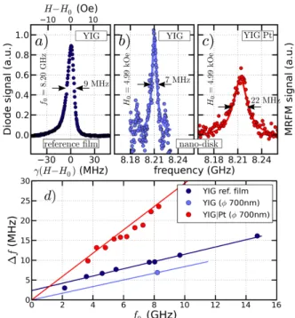
FIG. 3. (a) Low-power spectrum of the reference YIG film recorded at f0 = 8.2 GHz. Lineshape of the uniform mode
measured at H0= 4.99 kOe on the 700 nm disk bare (b, blue
circles) and with (c, red circles) Pt. (d) Dependence of the linewidth on the resonance frequency.
smallest disk.
From the comparative measurements presented in Fig. 2, we see that the peak position is not altered by the addition of the Pt layer ontop of the YIG disk whereas its linewidth is clearly increased. To emphasize this result, Fig. 3 shows the linear f-MRFM spectra of the 700 nm bare YIG (b, blue dots) and of the YIG|Pt (c, red dots) disks. For comparison the spectrum measured on the extended YIG thin film is shown in (a, black). It was recorded with a transmission line Au-antenna of 500 µm width and an in-plane external field oriented perpendic-ularly to the exciting microwave field, similarly to the configuration used in Ref.3.
A first striking result of Fig. 3 is obtained by compar-ing the spectra measured in extended film (a) and the nanostructure (b) for the bare YIG: the nanopatterning improves the linewidth7. One can observe that, while the lineshape of the resonance has a Lorentzian shape in the nanostruture (continuous line), the peak shape is asymetric in the YIG film. We attribute it to inhomoge-neous broadening. This is confirmed by performing ex-periments on different slabs of the reference film, which actually yield different lineshapes (not shown). The usual method of separating the homogeneous contribution from the inhomogeneous one is to study the frequency depen-dence of the half-linewidth ∆f /2. The slope gives α, the Gilbert damping constant, while the zero frequency inter-cept gives the inhomogeneous contribution. In Fig. 3(d), we have thus plotted the full-linewidth ∆f of the ex-tended reference film at different frequencies using the
same color as in Fig. 3(a). The linewidth varies almost linearly with the frequency. We extract from the slope the damping 4· 10−4, while the intercept at zero fre-quency indicates the amount of inhomogeneity of the res-onance: ∆f =2.5 MHz (or ∆H=1 Oe).
On the same Fig. 3(d), we show using red dots the frequency dependence of the linewidth of the YIG|Pt nanostructure. The fit of the slope yields αYIG|Pt =
13 · 10−4. The striking feature is that a linear fit now in-tercepts with the origin of coordinates. It means that the linewidth measured in the nanostructures directly yields the homogeneous contribution. For the bare YIG nan-odisk it was only possible to reliably extract the linear linewidth at one point at 8.2 GHz (blue dot). Inter-estingly enough the slope of the straight line from this point to the origin is exactly that of the line fitted to the extended film data. We speculate by analogy to the Pt/YIG case that the linewidth in the YIG nanostructure is purely homogeneous in nature, while the intrinsic part of the damping has been unaffected by the lithographic process.
In Fig. 3, we also see that the linewidth of the 700 nm YIG|Pt disk is 22 MHz (c) i.e. about three times wider than that of the 700 nm YIG disk, which is 7 MHz (b). The influence of an adjacent Pt layer is shown to increase the damping threefold through spin-pumping effect15.
The characteristic parameter for the efficiency of spin transfer across the interface and the accompanying in-crease of damping in YIG is the spin mixing conductance G↑↓. One can directly evaluate the increase of
damp-ing induced by the presence of the Pt layer. As we find αYIG= 4·10−4and αYIG|Pt= 13·10−4, we deduce a large
spin-pumping contribution αsp = 9 · 10−4 that adds to
the intrinsic damping : αYIG|Pt= αYIG+ αsp. From this,
one can calculate the spin mixing conductance according to16:
G↑↓= αsp
4πMSt
gµB
G0, (1)
where t = 20 nm is the YIG thickness, g the elec-tron Land´e factor, µB the Bohr magneton, and G0 =
2e2/h the quantum of conductance. This corresponds to: G↑↓= 1.55 · 1014Ω−1m−2 for our YIG|Pt interface.
In summary, we have conducted a study of spin wave spectra of individual submicron YIG and YIG|Pt disks. We find that the litography process does not broaden the linewidth and on the contrary, the linewitdh decreases compared to the extended film. The influence of an adja-cent Pt layer on the YIG through the spin pumping effect is investigated and quantified to increase the damping 3 fold. As a non zero spin mixing conductance is deter-mined, these experiments pave the way for observation of inverse spin Hall effects in a YIG|Pt nanodisk access-ing its individual spin wave modes. Most importantly, thanks to the small volume and purely intrinsic damp-ing of the YIG sample, we will address in future studies the influence of direct spin Hall effect on the linewidth
4 of these YIG nano-disks as it was demonstrated in
all-metallic NiFe/Pt dots17.
ACKNOWLEDGMENTS
This research was supported by the French Grants Trinidad (ASTRID 2012 program) and by the RTRA Triangle de la Physique grant Spinoscopy. We also ac-knowledge usefull contributions from C. Deranlot, A.H. Molpeceres and R. Lebourgeois.
1A. A. Serga, A. V. Chumak, and B. Hillebrands, Journal of
Physics D: Applied Physics 43, 264002 (2010)
2Y. Kajiwara, K. Harii, S. Takahashi, J. Ohe, K. Uchida,
M. Mizuguchi, H. Umezawa, H. Kawai, K. Ando, K. Takanashi, S. Maekawa, and E. Saitoh, Nature (London) 464, 262 (2010)
3C. Hahn, G. de Loubens, O. Klein, M. Viret, V. V. Naletov, and
J. Ben Youssef, Phys. Rev. B 87, 174417 (2013)
4O. d’Allivy Kelly, A. Anane, R. Bernard, J. Ben Youssef,
C. Hahn, A. H. Molpeceres, C. Carretero, E. Jacquet, C. Der-anlot, P. Bortolotti, R. Lebourgeois, J.-C. Mage, G. de Loubens, O. Klein, V. Cros, and A. Fert, Applied Physics Letters 103, 082408 (2013)
5J. Xiao and G. E. W. Bauer, Phys. Rev. Lett. 108, 217204 (2012) 6J. Jorzick, S. O. Demokritov, B. Hillebrands, M. Bailleul, C.
Fer-mon, K. Y. Guslienko, A. N. Slavin, D. V. Berkov, and N. L. Gorn, Phys. Rev. Lett. 88, 47204 (2002)
7G. de Loubens, V. V. Naletov, O. Klein, J. B. Youssef, F. Boust,
and N. Vukadinovic, Phys. Rev. Lett. 98, 127601 (2007)
8F. Guo, L. M. Belova, and R. D. McMichael, Phys. Rev. Lett.
110, 017601 (2013)
9P. Pirro, T. Brcher, A. V. Chumak, B. Lgel, C. Dubs,
O. Surzhenko, P. Grnert, B. Leven, and B. Hillebrands, Applied Physics Letters 104, 012402 (2014), http://scitation.aip.org/ content/aip/journal/apl/104/1/10.1063/1.4861343
10V. V. Naletov, G. de Loubens, G. Albuquerque, S. Borlenghi,
V. Cros, G. Faini, J. Grollier, H. Hurdequint, N. Locatelli, B. Pigeau, A. N. Slavin, V. S. Tiberkevich, C. Ulysse, T. Valet, and O. Klein, Phys. Rev. B 84, 224423 (Dec 2011), http: //link.aps.org/doi/10.1103/PhysRevB.84.224423
11O. Klein, G. de Loubens, V. V. Naletov, F. Boust, T. Guillet,
H. Hurdequint, A. Leksikov, A. N. Slavin, V. S. Tiberkevich, and N. Vukadinovic, Phys. Rev. B 78, 144410 (2008)
12M. Sparks, Ferromagnetic relaxation theory (McGraw-Hill, New
York, 1964)
13R. W. Damon and H. Van De Vaart, Journal of Applied
Physics 36, 3453 (1965), http://scitation.aip.org/content/ aip/journal/jap/36/11/10.1063/1.1703018
14K. Y. Guslienko, S. O. Demokritov, B. Hillebrands, and A. N.
Slavin, Phys. Rev. B 66, 132402 (Oct 2002), http://link.aps. org/doi/10.1103/PhysRevB.66.132402
15Y. Tserkovnyak, A. Brataas, and G. E. W. Bauer, Phys. Rev. B
66, 224403 (2002)
16B. Heinrich, C. Burrowes, E. Montoya, B. Kardasz, E. Girt, Y.-Y.
Song, Y. Sun, and M. Wu, Phys. Rev. Lett. 107, 066604 (2011)
17V. Demidov, S. Urazhdin, H. Ulrichs, V. Tiberkevich, A. Slavin,
D. Baither, G. Schmitz, and S. O. Demokritov, Nature Mater. (London) 11, 1028 (2012)