HAL Id: hal-01629860
https://hal.archives-ouvertes.fr/hal-01629860
Submitted on 6 Nov 2017
HAL is a multi-disciplinary open access
archive for the deposit and dissemination of
sci-entific research documents, whether they are
pub-lished or not. The documents may come from
teaching and research institutions in France or
abroad, or from public or private research centers.
L’archive ouverte pluridisciplinaire HAL, est
destinée au dépôt et à la diffusion de documents
scientifiques de niveau recherche, publiés ou non,
émanant des établissements d’enseignement et de
recherche français ou étrangers, des laboratoires
publics ou privés.
Modeling of Simultaneous Oxidation and Volatilization
Phenomena along a Crack in a Self-healing
Multi-constituent Material
Coraline Simon, Gérald Camus, Florent Bouillon, Francis Rebillat
To cite this version:
Coraline Simon, Gérald Camus, Florent Bouillon, Francis Rebillat. Modeling of Simultaneous
Ox-idation and Volatilization Phenomena along a Crack in a Self-healing Multi- constituent Material.
Oxidation of Metals, Springer Verlag, 2017, 87 (3-4), pp.381-392. �10.1007/s11085-016-9708-y�.
�hal-01629860�
1
Modeling of Simultaneous Oxidation and Volatilization
Phenomena along a Crack in a Self-healing
Multi-constituent Material
Coraline Simon
a,b, Gérald Camus
a, Florent Bouillon
b, Francis Rebillat
aaLaboratoire des Composites Thermostructuraux, (Université de Bordeaux-CNRS-CEA-SAFRAN), 3 allée de la
Boétie, 33600 Pessac, France
b SAFRAN Ceramics, Rue de Touban – Les 5 Chemins, 33185 Le Haillan, France
simon@lcts.u-bordeaux.fr; camus@lcts.u-bordeaux.fr; florent.bouillon@safrangroup.com; rebillat@lcts.u-bordeaux.fr
Abstract. Multi-layer Ceramic Matrix Composites with self-healing capacities have been developed for
high-temperature aeronautical applications. However, the use of these sophisticated materials lead to complex thermo-chemical behavior which requires a proper analysis. Previous models have allowed to determine the quantity of oxygen reaching the fiber at the end of a crack, in a dry atmosphere. The focus of this study was to extend this model to the case of humid atmospheres, for the presence of moisture can lead to the volatilization of the healing oxide. Applications of the model have been performed on a material composed of successive layers of SiC and B4C.
Changes of the crack wall surface could then be evaluated, as well as the healing or recession behavior, and the evolution of the oxygen concentration. Moreover, the introduction of a uniform equivalent averaged material allowed estimations of the consumption of all constituents, and in particular of carbon interphase, over durations representative of aeronautical service lives.
Keywords: Oxidation, modeling, self-healing matrix, volatilization
INTRODUCTION
Ceramic matrix composites such as SiC/SiC can be sensitive to oxidation in environments representative of aeronautical engine conditions. When oxygen reaches the interphase surrounding fibers through micro-cracks generated paths, this interphase can then be consumed by oxidation (above 400°C for pyrocarbon, which is the interphase of the composite considered in this study), which contributes to strongly reduce the mechanical properties of the material. That is the reason why self-healing composites based on a Si-B-C matrix have been developed, allowing healing of the cracks through the onset of an oxide glassy phase. However, this oxide tends to volatilize in the presence of moisture, which increases the duration required for healing and can even lead to a recession of the crack walls (thus completely impeding healing).
Various models have been proposed in order to evaluate the quantity of consumed interphase in a given environment: they respectively describe (i) a single crack surrounding a fiber [1,3], (ii) a crack orthogonal to the fiber [2], and (iii) a combination of those two approaches [4-6]. The effect of oxidation on the creep behavior has also been estimated through the introduction of a delay factor in the evolution of the quantity of consumed interphase [7]. All these models have been developed for less complex matrix architectures and/or for a dry
2
atmosphere, since they do not consider the volatilization of the oxide (except [3]). The introduction of the effects of humidity in a multi-constituent material, which can lead to the volatilization of the healing oxide, is therefore the focus of the present study.
The aim of this work is to build up a model representative of a crack network in multi-constituent materials, which can provide, in given environment conditions (including humidity), the evolution of the crack wall profile, the time required for healing, the evolution of the oxygen concentration profile inside the crack and the quantity of oxygen reaching the front line of this crack. Moreover, in order to take into account more complex geometries and larger scales closer to real parts, the introduction of an averaged material is proposed. The crack is then considered to be present in a uniform equivalent material displaying a behavior similar to that of the multi-constituent material. Hence the mesh of the FEM numerical method used in the model requires less refinement to provide results for larger scale geometries and longer time durations.
This method could be extended to other systems of complex architecture involving different constituents.
MODEL DESCRIPTION
The model is hereafter described in three steps. The main elements of the oxidation model in a dry atmosphere described in [6] are firstly summed up. In a second part, the introduction of the phenomenon of oxide volatilization is presented. Finally, the design of an equivalent averaged material is exposed.
Oxidation in Dry Atmosphere
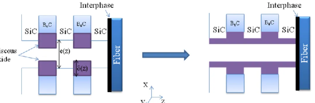
The specific composition of the material can be easily introduced in the model. As an example, the case of a matrix composed of 5 successive layers of two constituents (SiC and B4C, cf. Fig. 1), SiC Nicalon fibers, and a
pyrocarbon interphase is considered. Environment conditions and the geometry of the crack are given as inputs. In the presence of oxygen, the oxidation of SiC and B4C leads to the formation of condensed phases (respectively
SiO2 and B2O3) and the release of gas such as CO or CO2.
For each time step, the local quantity of oxygen consumed by the crack walls (depending on the local constituent) is calculated, taking into account the Fick and Knudsen regimes. The thickness of the oxide layer due to the oxidation of the local matrix constituent is also calculated.
These data are provided by the resolution of the following non-linear differential equation [1,2] through Gauss-Newton iterations and a finite element method approach:
0
)
(
)
(
)
(
)
1
(
1
)
(
)
(
2 2 0
Np r pi ox ox ox O O gas effC
z
C
z
K
M
n
n
dz
z
dC
X
n
n
z
e
z
D
dz
d
(1)where all symbols are described in the list of variables at the end of the paper.
The boundary condition at the crack front is provided by the consumption of oxygen by the carbon interphase, and is similar to the one proposed by Filipuzzi [1].
3
The local thickness of this oxide is given by a parabolic law until the crack may be considered as being sealed by an oxide “cork” [8]. In the case of the considered material, the oxide B2O3 is formed much quicker than SiO2 due to
its higher parabolic rate constant. Above 450°C, B2O3 is in a liquid state and tends therefore to spread along the
crack walls. This behavior is introduced by periodically reporting the oxide layer contributing to the sealing (above the initial crack surface) as a uniform layer all over the crack wall, as depicted in Fig. 1. The consequent oxide thickness δ(z) is then introduced in Eq.1 at the next time step.
When the crack is completely sealed with oxide, the diffusion of oxygen then can only occur within this oxide in a liquid state, leading to a dramatic decrease of its diffusion coefficient. The program keeps calculating the evolution of the oxygen profile after crack healing, and can therefore estimate the time for the oxygen to diffuse within the oxide over all the crack depth and to oxidize again the interphase.
Introduction of Volatilization in the Presence of Moisture
The healing oxide can volatilize in the presence of moisture: for instance, B2O3 will react with H2O to form
gaseous species such as H3BO3, H3B3O6 and HBO2 (later referred to as HxByOz). The partial pressure Pi of each of
these species is linked to the water pressure by its corresponding activation energy Eai, partial order Ni, and linear
rate constant Ki. The total pressure of HxByOz species is the sum of each partial pressure Pi weighted by ni, the
quantity of B2O3 in each mole of the gaseous species:
Ni i i i i i i i HxByOz
n
P
n
K
e
xp
Ea
RT
P
H
O
P
(
/
)
(
2)
3 1 3 1
(2) In the considered situation, the boron content is globally uniform along the crack, from the entrance to its front, (no punctual source is present as it would be the case with a BN interphase [3]), so that the formation of hydroxide may also be considered as uniform. Thus, the convective flow through the opened section of the crack is much lower than the diffusive flow [9], and the release of HxByOz out of this crack becomes the limiting step. Therefore, the rate-limiting mechanism is the removal of the gaseous species out of the crack and not the diffusion within the crack. This justifies considering the pressure of H2O (and consequently the pressure of HxByOz species) to beuniform along the crack.
This hypothesis implies that, at each time step, the “thickness” of the volatilized quantity is distributed evenly along the crack. If the local oxide thickness is lower than the thickness which has been calculated as to be volatilized, volatilization is transferred to the places where enough oxide is available, in order to keep the same global volatilized volume during this time step (in a conservative way).
FIGURE 2. Example of evolution of the oxide thickness during an oxide volatilization step and an oxide formation
step, in the case of a recession situation
The volatilization speed Vv of the oxide B2O3 depends on the maximum width of the crack e0, the length of the
crack Lf (in the y direction in Fig. 1), the speed of the gas in the hot zone vhot gas, the temperature T and the pressure
of HxByOz species PHxByOz:
RT
P
v
L
e
s
mol
V
v f hotgas HxByOz1
)
/
(
0
(3)4
At each time step, the local thickness of the generated oxide is calculated, and its possible spreading is taken into account (Fig. 1). The volatilization speed is then calculated, and the corresponding volatilized thickness is subtracted (with possible transfer where oxide is available).
This process is depicted in the case of a single B4C layer on Fig. 2: at time step t, this layer has given rise to a
thickness δ(t) of oxide. The volatilized thickness is calculated for a duration dt and subtracted, leading to an intermediate oxide thickness δ’(t), and reducing the surface position. In the next time step, the thickness of the generated oxide is calculated: the new position of the oxide surface depends on the generated oxide thickness multiplied by the volumetric expansion coefficient α introduced by oxidation. It can be noted that the amount of B4C
decreases during this operation, and this particular situation will lead to a recession of the B4C layers.
Towards Applications to Complex Geometries: Definition of an Averaged Material
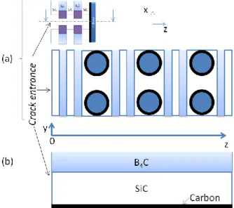
Solving the model described above requires a FEM mesh with several nodes for each constituent layer in order to be sufficiently accurate. Consequently, it is hardly transposable to much larger parts or durations of a few thousands of hours (as in aeronautical applications). The concept of an averaged material has therefore been developed: this averaged material is uniform, i.e. it does not possess different constituent layers, but it has an oxidation behavior similar to the multi-constituent material. Such a uniform material does not require a refined meshing, and would therefore allow calculations on larger space and time scales.This averaged material is described by the volumetric fraction of each of its constituent. In the case of a carbon interphase, the estimated volumetric fraction of carbon Xcarb is estimated and considered to be evenly distributed
within the material (which constitutes a rational hypothesis at the size of a sample). As represented on Fig. 3b, at each z position in the crack depth, the averaged material is uniform and contains a representative fraction of each constituent (in the plane (y,z) different from the plane (x,z) of Fig. 1). The degree of mixing of all the constituents is considered to have no influence on the local oxidation rate.
FIGURE 3. Representations of (a) the initial multi-layered material, (b) the averaged material related to (a)
The rate law which rules the thermo-chemical behavior of the material has to be adapted to the averaged version. The differential equation (1) refers to various constituent-dependent parameters which where locally evaluated on each node. For the uniform averaged material, equation (1) is adapted by adding the contribution of each constituent weighted by its volumetric fraction. In the case of a material containing SiC, B4C and a carbon interphase, equation
5
0
)
(
)
(
)
(
)
(
)
(
)
(
)
1
(
1
)
(
)
(
4 4 3 2 3 2 3 2 2 4 2 2 2 2 2 0
Nc r C carb C NpB r C pB O B O B O B O C B NpSiC r pSiC SiO SiO SiO O SiC O gas effC
z
C
K
X
C
z
C
z
K
M
n
n
X
C
z
C
z
K
M
n
n
X
dz
z
dC
X
n
n
z
e
z
D
dz
d
(4)where Kc is the linear rate constant for carbon and Nc its partial order.
The only space dependant parameters are the oxygen concentration C(z), and the thickness of the oxide layer δ(z) (which is linked to the crack width e(z) and the diffusion coefficient Deff(z)).
As previously explained, the reactivity of B4C is much higher than the one of SiC, and B2O3 is the main oxide
contributing to the healing of the crack. Therefore, for more efficiency of this version of the model, it is considered that B2O3 is the only present oxide. The contribution of SiC is taken into account to evaluate the oxygen
concentration (Eq.4), whereas its involvement in the oxide volume is negligible. At each time, the thickness of the oxide created, dδ is calculated on the basis of B4C volumetric fraction XB4C :
dt
z
C
z
C
K
X
d
C NpB r C pB C B)
(
2
1
)
(
4 4 4
(5)A coefficient β which depends on the volumetric fractions of SiC and B4C (β = 1 + XSiC/XB4C) is introduced in
order to consider the higher thickness of oxide provided by B4C in the calculation of the created oxide: in the
multi-constituent material, the oxide appears preferentially on the B4C layers, but if it is considered as being evenly
distributed, the B2O3 local thickness δ(z) (in regard to B4C) is underestimated and therefore the thickness dδ is
largely overestimated. Apart from this adaptation, all the previously described processes of oxide spreading and volatilization remain unchanged.
The carbon interphase is considered to be evenly distributed within the material with a volumetric fraction Xcarb.
At each time step and for each position z, the length of the local consumed interphase is given by:
dt
M
C
z
C
K
X
dl
C C Nc r C carb C
(
)
(6)This allows the evaluation of the profile of consumed interphase along the crack depth as well as of its evolution.
RESULTS AND DISCUSSION
Application to a Composite with a Matrix composed of 5 Layers in a Wet Atmosphere
The enhanced model handling volatilization has been applied to a material with a matrix made of five 4µm- layers of SiC and B4C, presenting a 2µm-large crack. The profile of the crack wall surface is depicted on Fig. 4 after1s and 50s of exposition under T=900°C and P(H2O) = 10 kPa. As the SiC layers are much less reactive than B4C,
the B4C layers are thus consumed much more rapidly, leading quickly to the non-uniform profile displayed in Fig.
4a. After 1s, a thin layer of oxide is present over the B4C layers, and the position of the top of this oxide layer is
about 0.4µm under the initial position of the sample surface. After 50s, the surface of the B4C layers is much lower
(-20µm) and the oxide is almost no longer present. Indeed, in such strong conditions, all the created oxide is immediately volatilized, leading to the recession of the B4C layers. For larger times and in a real material, the
formation of borosilicate, more stable, may contribute to a partial limitation of this layer recession [10].
The behavior of the material is different in the case of lower humidity pressures. As a reference, the same calculation has been performed in a dry atmosphere, i.e. with P(H2O) set up to zero. In such a dry atmosphere, the
6
Fig. 5a, with oscillations due to the periodic spreading of the liquid oxide. The surface has a parabolic evolution, and reaches 1µm (half of the crack opening, by symmetry) after 102s.
When P(H2O) is increased, a fraction of the oxide is volatilized, and the time before healing therefore increases.
However, when the water pressure reaches 3 kPa, a drastic change of behavior occurs: the maximum healing capacity in these conditions is slightly inferior to the semi-crack width (Fig. 5b), and the step of recession of the B4C
surface is reached (typical parabolic-linear evolution [11]). The crack will therefore no longer be sealed for water pressures above 3 kPa (all other conditions being identical).
This model accurately reproduces the behaviors of recession or healing typical of the competition between oxidation and volatilization. Such evolutions of crack wall surfaces are in good agreement with experimental observations on model linear cracks in real self-healing composites [14].
FIGURE 4. Thickness profile of a crack in a 5-layer CMC, Ptot = 105 Pa, P(O2)=2.104 Pa, P(H2O)=10 kPa, T =
900°C, gas speed: 1m/s (cold zone), at (a) t=1s and (b) t=50s
FIGURE 5. Evolution of the position of the crack wall surface in 5-layer CMC, Ptot = 105 Pa, P(O2)=2.104 Pa,
T =900°C, gas speed: 1m/s (cold zone), with (a) P(H2O) = 0 and (b) P(H2O) = 3 kPa
Averaged Material
In order to validate this global approach, the same geometry constituting a so-called reference material was first considered: five 4-µm layers of SiC and B4C, and a 2 µm-crack opening. The averaged material is then composed of
the related volumetric fraction of each component: 59.5% of SiC, 39.5% of B4C and 1% of carbon.
The calculated behaviors of the reference material and of the average material are compared in Table 1, for various pressures of H2O. It appears that the same type of behavior (healing or recession) is depicted in each
situation, and the numeric values of time before healing and surface position are sufficiently close in regard with the performed simplification.
(a)
(b)
Healing Recession
7
TABLE 1. Comparison of simulation results with the 5-layer material and the related averaged material, for various
levels of H2O pressure. Crack length: 20µm, crack width: 2µm, T = 900°C. For the recession cases, the given
surface positions are averaged values on the B4C layers.
P(H2O) = 0 P(H2O) = 1 kPa P(H2O) = 2 kPa P(H2O) = 3 kPa P(H2O) = 4 kPa
5-layer Material Healing 110s Healing 260s Healing 354s Recession Initial Surface +0.7µm at 1000s Recession Initial Surface -0.7µm at 1000s Averaged Material Healing 179s Healing 235s Healing 424s Recession Initial Surface +0.4µm at 1000s Recession Initial Surface -0.4µm at 1000s Once the correspondence between the two models had been evaluated with a small crack (total matrix thickness: 20µm) and short times, it then became possible to use the averaged material version on a much deeper crack (1mm matrix thickness, which is closer to its related averaged material than a superficial crack), and for extended time durations (with of course a less refined mesh). The calculations have been performed on this averaged material with P(H2O) = 1 kPa, and T = 900°C, and for a very thin crack opening of 2µm. As the crack is quickly sealed with
oxide, it was therefore more interesting to focus on the local length of consumed carbon interphase after various time durations (Fig. 6).
Indeed, as oxygen slowly diffuses within the liquid oxide, it reaches and oxidizes the carbon interphases closest to the crack entrance. After 100h, the interphases are attacked over the first 5 µm of the material, which is not bothering since no interphase is present so close to the surface within the real material. After 1000h, the interphases are consumed over about 8µm, and it is interesting to note that the consumed lengths are very high, which means that the material has no longer good mechanical capacities in this area. Indeed, over about 1 mm of consumed interphase at a given depth, it can be considered that all the interphase is oxidized at this depth, since the distance between two cracks is typically inferior to 1-2 mm (the calculated length of consumed interphase due to each crack would overlap). Finally, a calculation was performed for 20000h of ageing, which is closer to the required service lives in civil aeronautics. The interphases are estimated to be completely consumed over about 14µm from the surface of the material, which represents the portion of the material having lost its mechanical properties.
FIGURE 6. Evolution of the profile of consumed carbon interphase along a sealed 1mm deep crack, crack width:
2µm, Ptot = 10 5 Pa, P(O2)=2.10 4 Pa, P(H2O)=10 3
Pa, T = 900°C, gas speed: 0.1m/s (cold zone)
This type of estimation could be very valuable to assess the lifetimes of multi-constituent materials in various environmental conditions and over very long durations.
8
CONCLUSION
A model representing simultaneous oxidation and volatilization phenomena has been developed for multi-constituent self-healing materials damaged by a crack. The effects of humidity present in the environment are accurately represented, through the introduction of a delay before healing, or even, for higher water pressures, a complete impediment, leading to a recession of the crack walls. The geometries of the material and the crack are given as input and are easily adaptable. Environment conditions can be selected as well in a wide range, as long as the environmental conditions remain in the domain of definition of the overall oxidation kinetics laws. The evolution of the oxygen profile is given as one of the outputs of the model, allowing estimations of the length of consumed carbon interphase, which is critical for the material mechanical properties.
An averaged material was designed in order to get an assessment of the material behavior at larger time and space scales, with the goal of being closer to an element of an aeronautical part. Estimations of the consumed length of interphase were given as results in a typical configuration after tens of thousands of hours of exposition.
The borosilicate glass can progressively become enriched in silica with increases in time and temperature. The induced modification of the diffusion coefficient should be further taken into account, in agreement with the respective oxidation kinetics of each constituent and the dissolution of SiO2 into B2O3. This model is extendable to
almost any multi-constituent self-healing material, and the estimations provided by the averaged version could be very valuable in the assessment of the lifetime of the material under typical aeronautical conditions. The opening of cracks can be related to various applied mechanical stresses.
ACKNOWLEDGMENTS
This work was supported by the company SAFRAN Ceramics, which contributed to provide a PhD scholarship to C. Simon.
LIST OF VARIABLES
e(z) Crack width (m) ngas /nO2 Ratio of the number of moles of generated
gas on that of oxygen consumed
δ(z) Oxide layer thickness at the abscissa z (m) nO2/nox Ratio of the number of moles of oxygen
consumed on that of generated oxide Deff Effective diffusion coefficient (m2.s-1) Vv Volatilization speed (mol/s)
X0 Molar fraction of oxygen e0 Maximum width of the crack (m)
Cr Reference oxygen concentration (mol.m-3) Lf Length of the crack on the outside surface
(direction y on Fig. 1) Npi Partial order with respect to oxygen for
constituent i
vhot gas Gas velocity in the hot zone (m/s)
ρox Density of the local generated oxide (g.m
-3) X
i Volumetric fraction of constituent i
Mox Molar mass of the local generated oxide(g.mol-1) Kpi Parabolic rate constant for constituent i
(m2.s-1)
Mc Carbon molar mass (g.mol-1) Kc Linear rate constant for carbon oxidation
(mol.m-2.s-1)
ρC Carbon volumetric mass (g.m-3) Nc Partial order regarding oxygen for carbon
oxidation
Values of diffusivities of oxygen in air are taken from [15], and take into account both Fick and Knudsen diffusions. The diffusivity of oxygen in the oxide is deduced from Kp, the parabolic rate constant related to the oxide
formation (m2.s-1), according to Eq. 7 (as previously expressed for the SiC/SiO2 system [8]).
e m p ox
C
V
K
m
D
2
(7)9
with Vm the molar volume of the oxide (m3.mol-1), Ce the oxygen concentration within the gas environment (mol.m
-3
) and m the number of consumed O2 for a single generated mole of oxide.
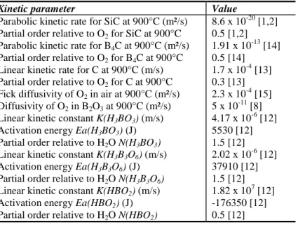
TABLE 2. Representative kinetic values used to create the displayed figures (kinetics for a reference partial
pressure of O2 = 105 Pa).
Kinetic parameter Value
Parabolic kinetic rate for SiC at 900°C (m²/s) 8.6 x 10⁻²⁰ [1,2] Partial order relative to O2 for SiC at 900°C 0.5 [1,2]
Parabolic kinetic rate for B4C at 900°C (m²/s) 1.91 x 10⁻¹³ [14]
Partial order relative to O2 for B4C at 900°C 0.5 [14]
Linear kinetic rate for C at 900°C (m/s) 1.7 x 10⁻⁴ [13] Partial order relative to O2 for C at 900°C 0.3 [13]
Fick diffusivity of O2 in air at 900°C (m²/s) 2.3 x 10⁻⁴ [15]
Diffusivity of O2 in B2O3 at 900°C (m²/s) 5 x 10-11 [8]
Linear kinetic constant K(H3BO3) (m/s) 4.17 x 10⁻⁶ [12]
Activation energy Ea(H3BO3) (J) 5530 [12]
Partial order relative to H2O N(H3BO3) 1.5 [12]
Linear kinetic constant K(H3B3O6) (m/s) 2.02 x 10⁻⁶ [12]
Activation energy Ea(H3B3O6) (J) 37910 [12]
Partial order relative to H2O N(H3B3O6) 1.5 [12]
Linear kinetic constant K(HBO2) (m/s) 1.82 x 10⁷ [12]
Activation energy Ea(HBO2) (J) -176350 [12]
Partial order relative to H2O N(HBO2) 0.5 [12]
REFERENCES
1. L. Fillipuzzi, R. Naslain, Journal of the American Ceramic Society 77 [2], 467-80 (1994).
2. F. Lamouroux, R. Naslain, J. Jouin, Journal of the American Ceramic Society 77 [8], 2058-68 (1994). 3. N. S. Jacobson, G.N. Morscher, D. R. Bryant, R. E. Tressler, Journal of the American Ceramic Society 82
[6] 1473-82 (1999).
4. A. G. Evans, F. W. Zok, R. M. McMeeking, Z. Z. Du, Journal of the American Ceramic Society 79 [9] 2345-52 (1996).
5. W. Xu, F. W. Zok, R. M. McMeeking, Journal of the American Ceramic Society 97 [11] 3676-3683 (2014).
6. F. Rebillat, "Modélisation de la progression de l'oxydation dans des composites modèles à matrice céramique auto-cicatrisante", Matériaux 2006 Conference Proceedings, Société de Chimie Industrielle, n°0625, 2006.
7. L. Casas and J.M. Martinez-Esnaola, Acta Materialia 51, 3745-57 (2003). 8. B. E. Deal, A.S. Grove, Journal of Applied Physic 36, 3770-78 (1965).
9. E. Garitte, "Etude de l'oxydation/corrosion des composites céramiques", PhD Thesis, Université Bordeaux 1, n°3484, 2007.
10. E.F. Riebling, Journal of the American Ceramic Society 47 [10] 478-483 (1964). 11. C. S. Tedmon, Journal of the Electrochemical Society, 766 (1966).
12. G. Eriksson, K. Hack, Metallurgical Transactions B, 21B, 1013 (1990). 13. I. W. Smith, Fuel 57, 409 (1978).
14. F. Rebillat, X. Martin, E. Garitte, A. Guette, Ceramic Transactions, 215, 151-66 (2010). 15. E. N. Fuller, G. C. Giddings, Ind. Eng. Chem., 58 [5] 18-27 (1966).