HAL Id: cea-02519398
https://hal-cea.archives-ouvertes.fr/cea-02519398
Submitted on 26 Mar 2020HAL is a multi-disciplinary open access
archive for the deposit and dissemination of sci-entific research documents, whether they are pub-lished or not. The documents may come from teaching and research institutions in France or abroad, or from public or private research centers.
L’archive ouverte pluridisciplinaire HAL, est destinée au dépôt et à la diffusion de documents scientifiques de niveau recherche, publiés ou non, émanant des établissements d’enseignement et de recherche français ou étrangers, des laboratoires publics ou privés.
The importance of the amount/thickness of die wall
lubricant for UO_2 pellets pressing
Ousseïni Marou Alzouma, Franck Marion, Anne-Charlotte Robisson
To cite this version:
Ousseïni Marou Alzouma, Franck Marion, Anne-Charlotte Robisson. The importance of the amount/thickness of die wall lubricant for UO_2 pellets pressing. Ceramics International, Elsevier, 2018, 44 (11), pp.12073-12080. �10.1016/j.ceramint.2018.03.224�. �cea-02519398�
Importance of the amount of lubricant on the die wall during UO
2powder cold
compaction
Ousseïni Marou Alzouma*, Anne-Charlotte Robisson CEA/DEN/DEC, Cadarache, 13108 Saint-Paul-Lez-Durance, France
*ousseini.maroualzouma@cea.fr, anne-charlotte.robisson@cea.fr *corresponding author
Abstract
External lubrication is often used to complete compaction process of powder materials. The main goal of this method is to reduce the amount of admixed internal lubricant (Zinc stearate spray) within the raw material. The application of external lubricants enhances the density uniformity and the mechanical strength of the resulting green pellets. This study investigates the effects of the external lubricant amount for UO2 powder compaction and the properties of the
corresponding green pellets. Results show that there is a quantity or number of layers from which, the external lubricant on the die wall becomes detrimental to the friction index and the ejection force measured during the pressing cycle. The quality of the green pellets (surface defects, mechanical resistance) can also be affected by a significant amount of lubricant. Thus the quantity of the die wall lubricant must be optimized in order to assure a mixed lubrication mode.
Keywords:Lubrication, friction index, ejection force, pellets, compaction, nuclear fuel, zinc stearate, die, uranium, density, powder, tribology
1. Introduction
Die wall lubrication or external lubrication during compaction is widely used in several technological fields such as powder metallurgy [1, 2, 3, 4, 5, 6, 7, 8], pharmaceutics [9, 10, 11] ceramic powders [12, 13], coal logs [14] and also in nuclear fuel [15, 16] in order to reduce friction phenomena at the interface between the compacted powder and the die wall.
Recently, C. Machio et al. [1] demonstrated that dry compaction of TiH2 powder, without lubricant on die walls, causes
the welding of TiH2 particles onto die walls and the rupture of the pellets during ejection while, when external lubricant
is applied, pellets green strength and densities are enhanced according to the lubricity of the lubricant and the ejection force is reduced. The same advantages are observed also in coal log compaction [14] and for pharmaceutics [10, 11]. Furthermore, contrary to internal lubrication, die wall lubrication avoids unwanted internal density distribution and allows low and stable friction coefficient as observed in ceramics compaction with zinc stearate [12]. On the other hand, it has been demonstrated that die wall lubrication reduces a need of the amount of admixed lubricant in the powder to compact [2, 4].
However, there is no data available concerning the tribological consequences of the thickness of the coating deposited on the die wall on the properties of the metallic or ceramic compacts which ensued from the pressing experiences. This work investigates the influence of the number of layers of lubricant deposited on the die wall for UO2 pressing.
Data recorded during pressing and ejection steps and characteristics of the UO2 green compacts are interpreted
according to the amount of lubricant on the die wall.
2. Experimental details
Raw material
A batch of dry processed UO2 powder elaborated by ANF Lingen is used to carry out the experiences. It contains around
8.5% of U3O8 additives. The powder depicted in Figure 1 presents a large particles size distribution (from 0.5 μm to 300
Figure 1 : UO2 powder particles observed by SEM technology.
Lubricants
The experiments are carried out with commercial zinc stearate spray. This universal release agent is often used as lubricant during forming process in different industrial fields. It allows the deposition solid coating on the surfaces in order to protect them against wear and friction phenomena. The commercial spray of zinc stearate used in this work contains some volatile organic elements such as: 1,1-Difluoroethane, Dimethyl ether and Dichlorofluoroethane which evaporate around two minutes after the lubricant deposition. The amount of these elements is not notified. However, it can be observed they seem to give a particular aspect to the coating formed by the StZn spray (Figure 2) with the presence of a quasi-continuous film with a suitable adhesion to the surface. The commercial StZn aerosol used in this study comes from IMS Company.
Figure 2 : Structure of zinc stearate spray deposited on a surface and observed by SEM technology. Compaction and lubrication methods
2.3.1 Lubrication methods
The variation of the amount of lubricant on the die wall is performed by two ways:
- the variation of the number of layers of StZn spray deposited on the die wall in order to increase the amount of lubricant; it is assumed that each spraying action corresponds to the formation of a layer of lubricant.
- for three layers of StZn spray, UO2 compacts are made consecutively one after the other until the lubricant
deposited is eliminated from the die wall (i.e: the first green pellet is noted N°1, the second N°2 and so on). 2.3.2 Compression method and data
The instrumented press used in this study is from INSTRON Company. The diameter of the mold is equal to 10 mm and the roughness Ra of the inner tungsten carbide surface of the die is equal to 0.4. The lower punch and the mold are fixed during the compaction process while the upper punch is moving to get contact with the powder to compress. The height of the chamber is fixed to 3.5 mm. The displacement speed of the upper punch is fixed to 2.1 mm/s. These compaction parameters allow to obtain green compact with an aspect ratio H/D close to 8/10, where H is the height and D is the diameter of the compact.
The friction index is calculated by Equation 1 including Janssen constant K and the friction coefficient nw [21]. This
parameter takes into account the geometry of the pellets, the applied and the transmitted forces which are obtained thanks to load cells located on the punches. Friction index takes into account the transgranular friction and the friction
between the surface of the pellet and the surface of the die wall. A large friction index is known to be detrimental to the compacts characteristics uniformity because of a non- suitable lubrication [14].
Friction index=nwK
=
𝑆𝑆
𝑝𝑝ℎ
𝑙𝑙𝑙𝑙(
𝜎𝜎𝜎𝜎
𝜎𝜎𝜎𝜎
)
Equation 1where S is the surface of the compact, p is the perimeter, h is the height,
σ
a andσ
t are respectively the stress applied bythe upper punch and the stress transmitted to the lower punch during compaction.
The transmitted force ratio σt/σa is also a parameter that explains the phenomena occurring at the interface powder/die
wall. In accordance with the literature, a high transmitted force is attributed to increasing of plastic flow and radial movement of particles during compaction [14].
The ejection force of the pellets after powder compaction is also widely considered to evaluate of the efficiency of die wall lubrication process [17]. This parameter is known to be the main factor which is responsible of the final state of the compacts after demolding [14, 17] in powder technology field. This force is directly recorded by the sensor placed under the lower punch.
2.3.3 Density measurement and green pellet surfaces characterization
Density is calculated geometrically by dividing the mass by the volume during the compression and after demolding considering a cylindrical geometry.
The surface characterization of the pellets is mainly carried out by SEM observations and analyzes. 2.3.4 Mechanical properties
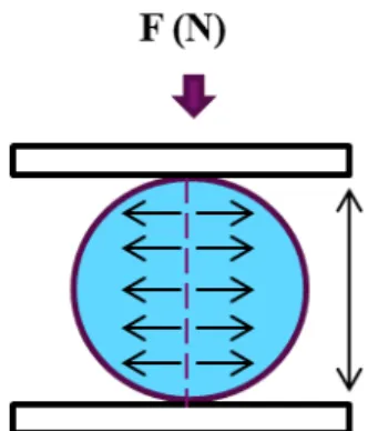
Indirect tensile tests are realized on the green compacts through Brazilian tests [18, 19] (Figure 3).
Figure 3 : Schematic illustration of Brazilian test principle.
Indirect tensile test involves loading a cylindrical specimen with compressive loads which act parallel along the vertical diametrical plane, as shown in Figure 3. To distribute the load and maintain a constant loading area, the compressive load is applied through a wide stainless steel punch. This loading configuration develops a relatively uniform tensile stress perpendicular to the direction of the applied load and along the vertical diametrical plane, which ultimately causes the specimen to fail by splitting or rupturing along the vertical diameter (Figure 3) [20]. The indirect tensile strength of a cylindrical sample with diameter D and thickness t is given by Equation 3.
Equation 2 where F is the failure load, t the thickness or the sample length.
Twenty specimens of UO2 compact are made for each lubricant for a suitable statistical analysis. Data are analyzed by
Weibull statistical law [21].
3. Results and discussions
Characterization during pressing cycle 3.1.1 Transmitted force ratio
wall. Indeed, the force transmission between the upper punch and the lower punch is lower for the last compacts (N°1 > N°2 > N°3). This result may be explained by the increasingly larger energy needed to shear the material at the lubricant/die wall interface due to the progressive depletion of the lubricant for the last compacts. These phenomena induce additional friction forces, probably due to the elastic deformation of single asperity in contact with the abrasive particles of UO2, which reduces the transmitted force ratio. It is important to notice that there is not any smearing
phenomenon corresponding to the accumulation of the external lubricant inside the matrix.
This analysis is confirmed by the results shown in Figure 4b, where the transmitted force ratio increases with the quantity of lubricant layers deposited on die wall (from 1 layer to 3 layers). However, when the coating formed by the lubricant becomes too thick (6 layers), the transmitted force ratio is lower compared to the cases with less lubricant. This means that thick coating hinders the force transmission between the upper and the lower punches. In this case, hydrodynamic lubrication predominates and the thick coating is probably removable due to its low adherence on the die wall which is associated to the movements of the punches and the powder [23].
(a) (b)
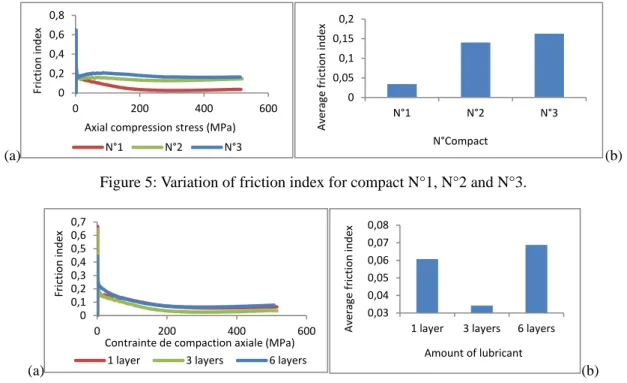
Figure 4: Transmitted force ratio (a) for compacts N°1, N°2 and N°3; (b) for different amount of lubricant. 3.1.2 Friction index
The calculation of the friction index corresponds to another way to represent the difference between the applied and transmitted forces. Its variation with the amount of lubricant (Figure 5) shows that the friction index is higher for the compacts N°2 and N°3. The decreasing of the transmitted force ratio with the depletion of the lubricant presented on the die wall is a consequence of the increase of the friction at the powder/die wall interface and intergranular friction. These results are also highlighted in Figure 6, where friction index decreases from 1 layer to 3 layers of lubricant. As already mentioned, the friction increases from 3 layers to 6 layers means that a thick coating leads to a weaker lubricant adherence.
(a) (b)
Figure 5: Variation of friction index for compact N°1, N°2 and N°3.
(a) (b)
Figure 6: Variation of friction index for compact made with different amounts of lubricant on the die wall.
0 0,2 0,4 0,6 0,8 1 0 20 40 Tr an sm itte d fo rc e r ati o
Applied normal load (kN)
N°1 N°2 N°3 0 0,2 0,4 0,6 0,8 1 0 20 40 Tr an sm itt ed for ce ra tion
Applied normal load (kN)
1 layer 3 layers 6 layers
0 0,2 0,4 0,6 0,8 0 200 400 600 Fr ict ion in de x
Axial compression stress (MPa)
N°1 N°2 N°3 0 0,05 0,1 0,15 0,2 N°1 N°2 N°3 Ave ra ge fr ict ion in de x N°Compact 0 0,1 0,2 0,3 0,4 0,5 0,6 0,7 0 200 400 600 Fr ict ion in de x
Contrainte de compaction axiale (MPa) 1 layer 3 layers 6 layers
0,03 0,04 0,05 0,06 0,07 0,08
1 layer 3 layers 6 layers
Ave ra ge fr ict ion in de x Amount of lubricant
Wall friction angle
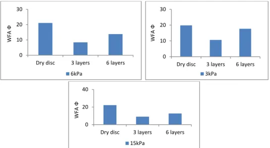
In order to complete the results obtained with the analyses during the cold pressing, the wall friction modulus of Freeman Technology Rheometer (FT4) is used to assess the friction at the interface powder/counter-body surface (Figure 7). The Wall Friction Angle φ (WFA) is a measure of resistance which describes the interaction between the powder and surface material (hopper, punch, die wall, etc…) [22]. This parameter gives information only about interactions at the interface, on the contrary, the friction index which involves also intergranular interactions. The WFA corresponds to a testing coupon of the wall material (tungsten carbide WC with a roughness Ra of 0.4 in this study) in a shear tester with the UO2 powder. WFA represents the angle derived from the curve of the shear stress τ as a function of
the normal stress σ as shown in Figure 7.
(a) (b)
Figure 7: (a) Schematic representation of the wall friction test with Freeman rheometer; (b) WFA calculation curve.
Even though the WC disk solicitation is relatively different from the die wall solicitation during powder compaction stage, the wall friction modulus of FT4 may help to assess lubrication conditions and select suitable coating.
In this work, the WFA is determined for three different normal loads (3 kPa, 6 kPa and 15 kPa) in three testing conditions: • tungsten carbide dry disk
• three layers of StZn spray on the tungsten carbide disk • six layers of StZn spray on the tungsten carbide disk
On the one hand, the results show that the WFA decreases when three layers of StZn spray are deposited on the WC disc, compared to the case of the dry disc for the three tested applied loads. On the other hand, the WFA increases between three and six layers of StZn spray for the three tested conditions, results in good agreement with compaction experiments described in section 3.1.1 and 3.1.2 (Figure 8). This result confirms that there may be an optimum thickness and amount of lubricant to reduce the friction between UO2 particles and the die wall. For six layers, due to an hydrodynamic
lubrication mode [23], the lubricant particles do not support the applied pressure and their mobility seems to increase the resistance and the friction between UO2 powder and the die wall. Due to the high hardness of the tungsten carbide, there
was not enough wear phenomena to analyze it on the studied surface.
Figure 8: Comparison of WFA for different layers of lubricant on the die wall and for different normal stress.
0 10 20 30
Dry disc 3 layers 6 layers
W FA Ф 6kPa 0 10 20 30
Dry disc 3 layers 6 layers
W FA Ф 3kPa 0 20 40
Dry disc 3 layers 6 layers
W
FA
Ф
Ejection force
The analysis of the ejection force allows the assessment of the action of the lubricant coating during the compact ejection. Figure 9 shows a good correlation with the observations made during the compression step. The ejection force logically decreases with the depletion of lubricant on die wall. The thickness of the coating is progressively reduced until a mixed lubrication mode [23] which can be detrimental to the mechanical strength of the compacts if the lubricant quantity becomes too low.
Figure 9b shows that the ejection force is lower for the application of three layers of lubricant compared to the application of one layer, but it increases if six layers of lubricant are applied. This observation confirms that a very thick zinc stearate coating probably reduces its adherence on the die wall. Therefore, the residual coating that remains during ejection on the die wall becomes insufficient to reduce enough friction at the interface during this last step. These results show that the ejection force could be a relevant parameter to adjust the lubricant quantity in order to find optimal lubrication conditions.
(a) (b)
Figure 9 : Variation of the ejection force corresponding to (a) the compacts N°1, N°2 and N°3 and (b) the different amounts of lubricant on the die wall.
Green pellets characterization 3.4.1 Surface characterization
In order to complete the analysis made during pressing cycle, the surfaces of the compacts N°1, N°2 and N°3 are observed macroscopically to verify a correlation with the previous findings. The surface state of the compacts N°1, N°2 and N°3, shown in Figure 10, underscores that a depletion of the lubricant is detrimental to the quality and the mechanical strength of the compacts. Thus, severe cracks are observed on the lower tip of the compact N°3, and to a lesser extent on the top of the compact N°2. There are no microcracks on the tip of the compact N°1, but some part of the coating is pulled out to the ejection stage when the compact is collected. This is probably due to a non-optimal lubrication of the die wall, but not detrimental to the UO2 compact (N°1), and some inhomogeneous residual zinc
stearate coating is visible on the compact surface. The results of this section show that it is important to refresh the lubrication after each compact.
N°1 N°2 N°3
Figure 10 : UO2 green compacts surface state corresponding to the compacts N°1, N°2 and N°3.
3.4.2 Mechanical properties
The green densities of entire compacts have been measured. Results reported in Table 4 do not show significant difference as a function of the lubricant quantity in the studied compression conditions.
Diametric compression tests realized on entire green compacts showed that the tensile strength is reduced by the progressive depletion of the lubricant (σN°1> σN°2), as shown in Table 4 where σ0 represents the tensile yield stress
obtained using Weibull statistical law [21]. However, these tests were not performed on compact N°3 and those issued from six lubricant layers because of their experienced fragility which leads to notable damages (Figure 10) or even broken compacts. The same value of the tensile strength for compacts obtained with one layer and three layers of
0 5 10 0 5 10 15 20 Ej ec tion for ce (k N) Duration (seconds) N°1 N°2 N°3 0 1 2 3 0 10 20 Ej ec tion for ce (k N) Duration (seconds)
lubricant is not explainable at the moment and these experiments need to be investigated in more details. Furthermore, it underlines that small variations of friction index and/or ejection force do not imply systematically mechanical strength variations, which seems to be a less sensitive parameter.
Table 1 : UO2 green compacts tensile yield stress and their density.
Compacts Tensile yield stress σ0 MPa Density (g/cm3)
N°1 2,06 6,2 ± 0,08
N°2 1,5 6,0 ± 0,09
1 layer 2,12 6,2 ± 0,07 3 layers 2,06 6,2 ± 0,08
4. Conclusions
In summary of this work, the following conclusions can be drawn:
• During the pressing cycle, the amount of lubricant deposited on the die wall has an influence on the friction index, the wall friction force, the ejection force and the green pellet mechanical strength;
• It is important to optimize the thickness of the lubricant coating in die wall lubrication in order to optimize the quality of the ensued compacts. Friction index and ejection force seem to be the more sensitive parameter to perform this optimization;
• The renewal of the lubricant on the die wall is important because the consecutive fabrication of compacts from an initial amount of lubricant induces the depletion of the lubricant and weakens the resistance of the
compacts.
Acknowledgments
The authors would like to acknowledge AREVA NC and EDF for the financial support of this work.
5. References
[1] C. Machio, R. Machaka, H.K. Chikwanda, “Consolidation of titanium hybride powders during the production of titanium PM parts : The effect of die wall lubricants”, Materials and Design 90 (2016) 757-766
[2] M. Uppalapati, D.J. Green, « Effect of external lubricant on mechanical properties of dry-pressed green bodies », J.
Am. Ceram. Soc. , 88(6) 1397-1402 (2005).
[3] A. Rawlings, S. Luk, F. Hanejko, “Engineered Approach to High Density Forming using Internal and External Lubricants”, Hoeganaes Corporation, Cinnaminson, NJ 08077
[4] P. Lemieux, Y. Thomas, P.E. Mongeon, S. Pelletier, S. St-Laurent, “Benefits of die wall lubricationfor powder compaction”, paper presented at International conference PM2TECH 2003, Adv. Powder Metall. & Particul Mater, At Las Vegas, NV, USA, Volume: 3 (2003)
[5] P. Lemieux, S. Pelletier, P.E. Mongeon, Y. Thomas, L.P. Lefebvre, F. Chagnon, “A new approach to die wall lubrication for P/M application”, Paper presented at the 2001 International Conference of Powder Metallurgy &
Particulate Materials (PM2TEC’2001), May 13-17, 2001 New Orleans, Louisiana
[6] X. Yang, S.J. Guo, B.F. Chen, F. Meng, Y.D. Lian, “Electrostatic performance of various lubricant powders in P/M electrostatic die wall lubrication”, Powder Technology 164 (2006) 75-81
[7] W.G. Ball, P.F. Hibner, F.W. Hinger, J.E. Peterson, R.R. Phillips, New die wall lubrication system, The
International Journal of Powder Metallurgy, Volume 33, N°1, 1997, 23-30
[8] A. Simchi, Effects of lubrication procedure on the consolidation, sintering and microstructural features of powder compacts, Materials and Design, 24 (2003) 585-594
[9] T. Yamamura, T. Ohta, T. Taira, Y. Ogawa, Y. Sakai, K. Moribe, K. Yamamoto, Effects of automated external lubrication on tablet properties and the stability of eprazinone hydrochloride, International Journal of Pharmaceutics 370 (2009) 1-7
[10] J. Mosig, P. Kleinebudde, Evaluation of lubrication methods: How to generate a comparable lubrication for dry granules and powder material for tableting process, Powder Technology, 266 (2014) 156-166
[11] J. Wang, H. Wen, D. Desai, Lubrication in tablet formulations, European Journal of Pharmaceutics and
Biopharmaceutics, 75 (2010) 1-15
[12] B.J. Briscoe, S.L. Rough, “The effects of wall friction in powder compaction, Colloids and Surfaces”, A:
Physicochemical and Engineering Aspects 137 (1998) 103-116
[13] B.J. Briscoe, P.D. Evans, « Wall friction in the compaction of agglomerated ceramic powders », Powder Technology, 65 (1991) 7-20
[14] Y. Li, H. Liu, A. Rockabrand, « Wall friction and lubrication during compaction of coal logs », Powder Technology 87 (1996) 259-267
[15] K. Sudo, T. Takano, K. Takeuchi, Y. Kihara, M. Kato, “Development of Pressing Machine with a Die Wall Lubrication System for the Simplified MOX Pellet Fabrication Method in the FaCT Project”, Proceedings of Global 2011, Makuhari, Japan, Dec. 11-16, 2011, Paper No. 387512
[16] K. Asakura, K. Takeuchi, T. Makino, Y. Kato, Feasibility study on a simplified MOX pellet fabrication process, the short process, for fast breeder reactor fuel, Nuclear Technology, vol. 167, sep. 2009,
[17] E.N. Hiestand, J.E. Wells, C.B. Peot, J.F. Ochs, “Physical Processes of Tableting”, Journal of Pharmaceutical
Sciences, Volume 66, Issue 4, April 1977, Pages 510-519
[18] D.K. Shetty, A.R. Rosenfield, W.H. Duckworth, “Mixed-mode fracture of ceramics in diametral compression”, J.
Amer. Ceram. Soc., 69 (6), pp. 437-443, 1986
[19] F. Gálvez, J. Rodríguez, V. Sánchez, “Tensile strength measurements of ceramic materials at high rates of strain”,
J. de Physique IV, Colloque C3 pp.151-156, 1997
[20] James N. Anagnos Thomas W. Kennedy, “Practical method of conducting the indirect tensile test”, Research
Report Number 98-10, Center for Highway Research, the University of Texas at Austin, August 1972
[21] J. McCool, “Analysis of sets of two-parameter Weibull data arising in rolling contact endurance testing, rolling contact fatigue testing of bearing steels”, ASTM STP 771 (1982) Pages 293-319
[22] T. Freeman, J.Cook, K. Brockbank, B. Armstrong, J. Yin, “An Investigation into the Wall Friction Angle of a Range of Vessel/Equipment Coatings Used in Pharmaceutical Processing Equipment”, Freeman Technology, EM Coating Services
[23] J. Sotres, T. Arnebrant, “Experimental Investigations of Biological Lubrication at the Nanoscale: The Cases of Synovial Joints and the Oral Cavity”, Lubricants, 2013, 1(4), 102-131