HAL Id: hal-02163939
https://hal.archives-ouvertes.fr/hal-02163939
Submitted on 24 Jun 2019
HAL is a multi-disciplinary open access
archive for the deposit and dissemination of
sci-entific research documents, whether they are
pub-lished or not. The documents may come from
teaching and research institutions in France or
abroad, or from public or private research centers.
L’archive ouverte pluridisciplinaire HAL, est
destinée au dépôt et à la diffusion de documents
scientifiques de niveau recherche, publiés ou non,
émanant des établissements d’enseignement et de
recherche français ou étrangers, des laboratoires
publics ou privés.
Adaptive optics light-sheet microscopy based on direct
wavefront sensing without any guide star
Antoine Hubert, Fabrice Harms, Remy Juvénal, Pauline Treimany, Xavier
Levecq, Vincent Loriette, Georges Farkouh, François Rouyer, Alexandra
Fragola
To cite this version:
Antoine Hubert, Fabrice Harms, Remy Juvénal, Pauline Treimany, Xavier Levecq, et al.. Adaptive
optics light-sheet microscopy based on direct wavefront sensing without any guide star. Optics Letters,
Optical Society of America - OSA Publishing, 2019, 44 (10), pp.2514. �10.1364/OL.44.002514�.
�hal-02163939�
Adaptive Optics Light-Sheet Microscopy based on direct wavefront
sensing without any guide star
A
NTOINEH
UBERT1,2,*, F
ABRICEH
ARMS2, R
ÉMYJ
UVÉNAL2, P
AULINET
REIMANY2, X
AVIERL
EVECQ2,
V
INCENTL
ORIETTE1, G
EORGESF
ARKOUH3, F
RANÇOISR
OUYER3,
ANDA
LEXANDRAF
RAGOLA11Laboratoire Physique et Etudes des Matériaux, ESPCI Paris, PSL Research University, CNRS, Sorbonne Université 10 rue Vauquelin 75005 Paris, France 2Imagine Optic, 91400 Orsay, France
3Institut des Neurosciences Paris-Saclay, Univ. Paris-Sud, CNRS, Université Paris-Saclay, 91190 Gif-Sur-Yvette, France *Corresponding author: [email protected]
We propose an Adaptive Optics Light-Sheet Fluorescence Microscope (AO-LSFM) for closed-loop aber-rations correction at the emission path, providing intrinsic instrumental simplicity and high accuracy when compared to previously reported schemes. The approach is based on direct wavefront sensing i.e. not on time-consuming iterative algorithms, and does not require the use of any guide star thus reducing instru-mental complexity and/or sample preparation constraints.
The design is based on a modified Shack-Hartmann wavefront sensor providing compatibility with ex-tended sources such as images from optical sectioning microscopes. We report an AO-LSFM setup based on such sensor including characterization of the sensor performance, and demonstrate for the first time significant contrast improvement on neuronal structures of the ex-vivo adult drosophila brain in depth.
©2019 Optical Society of America. One print or electronic copy may be made for personal use only. Systematic reproduction and distribution, duplication of any material in this paper for a fee or for commercial purposes, or
modifications of the content of this paper are prohibite. When targeting reliable diagnosis and efficient
ther-apy of neurological diseases, understanding brain func-tions is of key importance. Neuroimaging now benefits from spectacular breakthroughs in biochemistry and mi-croscopy, thanks to the availability of new genetically-encoded reporters such as GCaMP and of advanced op-tical sectioning techniques such as Light-Sheet or
Mul-tiphoton microscopy [? ] [? ] [? ]. These
tech-niques can provide structural and functional images of neuron networks with high spatio-temporal resolu-tion, on semi-transparent animal models such as Ze-braFish or Drosophila larvae [? ] [? ], with minimized photo-toxicity in particular in the case of Light-Sheet mi-croscopy. Still, one major limitation of such techniques when imaging at large depths is the presence of optical aberrations that arise from inhomogeneities of the sam-ple as well as from residual aberrations of the optical setup.
Thus, there has been considerable recent efforts in devel-oping adaptive optics (AO) methods to compensate for optical aberrations in microscopy, and provide increased contrast and resolution in depth [? ] [? ]. Reported approaches mainly differ regarding implemented wave-front (WF) sensing methods, which can be grouped into two categories: indirect WF sensing methods based on
iterative algorithms estimating the WF from its impact on image quality, and direct WF sensing methods based on real-time WF measurement from a point source act-ing as a "guide star" - as originally defined in astronom-ical AO - in the imaging plane. The former makes use of a merit function such as image intensity or sharpness [? ] [? ], does not require a WF sensor, and still pro-vides image enhancement with moderate scattering con-ditions. It is however time consuming, which increases phototoxicity, whereas direct WF sensing, usually based on a Shack-Hartmann (SH) WF sensor, provides best reli-ability, speed, and compatibility with in-vivo imaging [? ].
LSFM, thanks to its low phototoxicity and speed capa-bilities, is now increasingly used for both structural and even functional neuroimaging [? ]. Only a couple of AO setups using direct WF sensing have been proposed for LSFM, targeting increased contrast and resolution, and mainly applied to the correction of aberrations at the emission path. Due to the need for a guide star in di-rect WF sensing, reported setups either make use of flu-orescent beads in the sample [? ] which is practically not compatible with biological studies in particular in neuroscience, or make use of an ultrafast laser to locally induce a fluorescent source through a nonlinear
multi-photon process and a scan/de-scan acquisition geometry [? ], which corresponds to significant instrumental com-plexity and cost. Recently, Kner et al. [? ] proposed an AO Light-Sheet setup using a scene-based SH WF sensor as originally developed in astronomy and Earth observa-tion [? ] [? ], but failed to provide aberraobserva-tions correcobserva-tion. This approach allows to get rid of the need for a guide star, providing simple AO implementation based on di-rect WF sensing.
In this letter, we report for the first time AO-LSFM im-ages of neuronal structures involved in sleep behavior in the ex-vivo adult drosophila brain, showing significant image quality improvement in depth, using closed-loop AO correction of aberrations at the emission path with-out the use of a guide star. We describe our experimental setup, including detailed design and performance char-acterization of the specific SH WF sensor providing com-patibility with extended sources. We discuss the impact of the characteristics of the sample on AO performance such as WF sensing accuracy and anisoplanetism, and provide strategies to further enhance the technique re-garding photometry and extension of the corrected field-of-view (FOV).
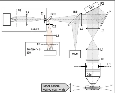
Our optical setup is presented in figure 1 and is
com-Figure 1.Optical setup. L1-5: relay lenses; IF: interfer-ence fluorescinterfer-ence filter; M: mirror; DM: deformable mir-ror; D1-2: field diaphragms; BS1-2: 50:50 non-polarizing beamsplitters; CAM: imaging camera. P1-4 are conju-gated pupil planes.
posed of a light-sheet excitation module and an AO loop included in the emission path. The conventional light sheet illumination module includes a 488nm laser source (Cobolt), a 10x NA 0.3 objective lens (Olympus) with a 1mm diameter diaphragm at the pupil plane to generate a pencil beam, a galvanometer mirror (Thorlabs) used to scan the beam over the FOV, and a custom sample cham-ber filled with sample medium with a 0.17mm thick
cov-erslip as the optical interface. This illumination setup cre-ates a gaussian beam with 7µm thickness FWHM and a Rayleigh range of 160 µm, both measured in the object plane. The design of the AO part corresponds to a closed loop configuration with the deformable mirror (DM) (Mi-rao52e, Imagine Eyes) prior to the custom, extended-source SH sensor (ESSH). Imaging is performed with a 25x NA 0.95 water-immersion objective lens (Leica) and a sCMOS camera (Hamamatsu Orca Flash v2). A conven-tional SH (Imagine Optic Haso3 First, 32x40 microlenses, lambda/100 accuracy) is also included as a reference SH sensor for performance assessment.
The ESSH WF sensor is made of a 17x23 microlens array, each microlens defining a 43x43 pixels area on a global shutter scientific CMOS camera with 6.9µm per pixel, a conjugation lens and an adjustable, square shaped field diaphgram in order to avoid crosstalk between sub-images formed by adjacent microlenses. The illumina-tion beam scan rate is significantly higher than the ESSH camera acquisition rate. The focal length/diameter
ra-tio of each microlens is fmic/Dmic = 17, corresponding
to low numerical aperture (NA), and each sub-image is sampled just above the diffraction limit in order to pro-vide a good trade-off between the FOV defined by the size of a microlens and the measurement accuracy. WF slopes are directly computed from the positions of in-tercorrelation peaks between sub-images, as previously reported in the field of astronomy [? ] [? ]. Each mi-crolens defines a 132x132 µm FOV in the object plane, and the reconstructed WF, using a conventional zonal method, is representative of an average aberration map over this FOV. Figure 2 shows a raw ESSH image of a fluorescent live cell, and comparative images from one microlens and from the LSFM camera.
Since WF measurement accuracy is driving AO
per-Figure 2. (a) raw ESSH image of a HeLa cell (GFP -tubulin) (b) Image on scientific camera (c) Zoom on one ESSH sub-image
is required. For this purpose, we use the reference SH sensor to drive the DM, such that a set of pure Zernike modes of known amplitudes are generated, taking into account aberrations of the optical setup as well as dif-ferential aberrations between the two WF sensing paths. A sample made of sparse 2µm fluorescent beads
(Ther-moFischer, λ=515nm emission) deposited between two
coverslips is used to provide both a guide star for the SH sensor by selecting one bead at the center of the FOV us-ing field diaphragm D2, and an extended source for the ESSH by using its field diaphragm D1 of larger extent. Static aberrations of the optical system are first measured and corrected before adding known aberrations. Figure 3 shows the WF difference between measurements from the 2 sensors as computed using Zernike coefficients, demonstrating a relative accuracy better than λ/50 over
a range of ±200nm rms of induced 3rd order
aberra-tions. Since the 2 sensors have a significant difference in spatial resolution and since the 2 WF measurement paths have different magnifications, the calculation of the Zernike pupil size and centre for each sensor is likely to exhibit some relative inaccuracy: this probably explains the increasing residual WF difference with larger gener-ated WF amplitude, particularly for spherical aberration which is very sensitive to pupil edge effects. However, these results demonstrate good accuracy of the ESSH, adapted to AO-based imaging. Since the ESSH method
Figure 3.ESSH WF measurement accuracy for 3rd order aberrations as compared with the reference SH
is based on imaging, WF measurement accuracy is also driven by the characteristics of the image of the sam-ple through microlenses, whereas the conventional SH approach benefits from diffraction-limited images of a mandatory point source. In particular, the spatial fre-quency content of sub-images formed by the ESSH im-pact the geometry of intercorrelation peaks, and as a con-sequence their localization accuracy which drives the WF
measurement accuracy. Each microlens of the ESSH acts as a low-pass filter in the Fourier domain, with a NA
of N Amic ' Dmic/2 fmic ' 0.03 as compared to the NA
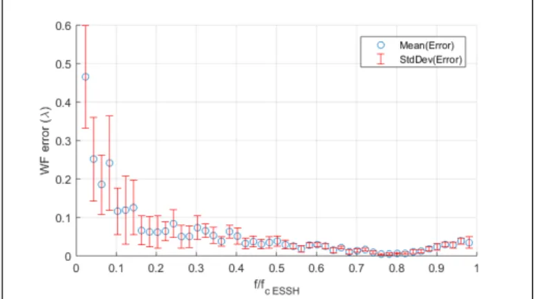
of 0.95 of the microscope objective. Intercorrelations of sub-images of the ESSH are thus based on low spatial frequencies of the object. In order to characterize the impact of this parameter, we simulated an object with variable 2D spatial frequency - generated from a random set of 2D sine patterns, we computed the corresponding image through a microlens, sampled in accordance with our ESSH design, calculated its positioning error for a given image shift, and converted it to the proportional WF error at the level of a microlens. The results are
pre-Figure 4.WF error as a function of the sample
normal-ized spatial frequency ( fcESSH= cut-off frequency of a
microlens). Each point (blue dot) is the average WF er-ror computed from a set of 10 sine patterns randomly generated - in order to take into account sampling ef-fects - and a corresponding set of 10 image shifts ran-domly distributed over a range describing a WF error
of±λ. Error bars are thus calculated from 100
measure-ments.
sented in Figure 4: expected accuracy is < λ/20 over
the whole spatial frequency range of a microlens, except for very low frequencies corresponding to very smooth patterns that fail to provide accurate intercorrelation, but that can easily be rejected by high-pass pre-filtering of sub-images. Moreover, for highest spatial frequencies, typically corresponding to the fluorescent beads used in the previous experiment, the expected accuracy reaches
up to < λ/50, consistently with the results of Figure 3.
WF sensing based on ESSH is likely to fail for objects solely containing high spatial frequencies, in particular higher than the cut-off frequency of a microlens. When studying samples where structures of interest are very small, this suggests that an additional labeling, for ex-ample structural, might be beneficial to the reported ap-proach, all the more that such labeling can be done at a given emission wavelength that can be specifically used for WF measurement, thus avoiding the need to share photons between the WF sensing and the imaging path, as done in the present straightforward setup.
In order to demonstrate image quality improvement of the reported AO-LSFM setup, we imaged a freshly dissected adult drosophila brain, with sleep neurons expressing GFP (23E10-GAL4>UAS-CD8-GFP), without any sample processing such as fixation and clarification. Figure 5 shows raw AO-LSFM images of cells bodies of the ExF12 neuronal group of the dorsal fan-shaped body [? ] at a depth of approximately 40µm without and with AO, without any deconvolution applied. In this exper-iment, static aberrations of the optical setup as well as differential aberrations between the imaging camera and the WF sensing path have been pre-compensated, so that comparative images only provide the effect of correcting aberrations arising from the sample. The AO loop is run-ning at approximately 2Hz in the experiment, currently limited by the amount of signal availaible for the ESSH, since fluorescence signal is shared between imaging and WF sensing in this first version of the setup. WF residual drops from 80nm to 25nm rms through the AO process, based on the correction of the first 30 modes of the inter-action matrix. This residual approximately corresponds to λ/20, below the Marechal criterion for a diffraction-limited image.
Intensity profiles along cellular structures show clear contrast and resolution enhancement using AO. On a small cell body of about 10µm in diameter, profiles (pink line in Figure 5) show a 50% increase in contrast, while on a larger cell, profiles (green line in Figure 5) show that AO correction provides a sharper cell contour. The Full Width at Half Maximum (FWHM) of the profiles with-out and with AO decreases from 12 to 9µm, suggesting significant resolution increase already at moderate depth. The ESSH FOV is marked using a dotted square in Figure 5: structures outside this area do not fully benefit from AO correction.
In the ESSH method applied to microscopy, as
previ-ously explained, N Amicis much smaller than N Aobj. The
depth of focus (DoF) of a microlens is thereby signifi-cantly larger than the DoF of the objective, so that each microlens provides an in focus image of the sample over a huge axial extent. Therefore, in order to provide an accurate WF measurement corresponding to the imag-ing plane, optical sectionimag-ing is a mandatory feature to be used with ESSH, for intercorrelations to be done on structures of the sole imaging plane. This corresponds to providing a "guide plane", instead of a guide star for SH. This constraint is however far more acceptable since modern microscopy techniques such as LSFM now rely on optical sectioning to provide 3D imaging with en-hanced SNR. Also, we showed that, due to the use of low spatial frequencies of the sample in the ESSH ap-proach, a supplementary structural labeling is beneficial to robust WF sensing and photometry. This constraint is also more acceptable for biologists than using beads, such labeling being already widely used for anatomical mapping, in conjunction or not with specific functional reporters, in particular in neuroimaging. We will
imple-Figure 5. GFP-expressing ExF12 neurons of the dorsal fan-shaped body around 40µm deep inside a freshly dis-sected adult drosophila brain, without (top) and with (bottom) AO. (a) to (d): intensity profiles of cell bodies along the pink and green lines showing SNR and
reso-lution enhancement with AO. Insert: 350x350µm2full
FOV image. Dotted square: ESSH/AO correction FOV
ment dual-labeling sample preparation and correspond-ing detection in the next version of our AO-LSFM setup. Sampling of sub-images in ESSH is a key design param-eter: each sub-image defines the WF measurement FOV, and minimal sampling is required to ensure accurate in-tercorrelation, so that more pixels per microlens are nec-essary when compared to conventional SH. As a result, ESSH usually provides less WF sampling than SH, or requires the use of megapixels cameras. This might be seen as a limitation when targeting high order aberra-tions characterization. In particular, this design param-eter needs to be carefully considered in conjunction with the DM used, in order to ensure that the spatial correc-tion modes of the DM, depending on its geometry, are sampled enough by the WF sensor. In our setup, the DM exhibits 8 actuators along a diameter corresponding to 14 microlenses of the ESSH, which provides proper sam-pling of the WF regarding DM spatial capabilities. Anisoplanetism is a practical limitation of AO when tar-geting aberration-corrected images of complex samples over a large FOV. A typical size of the isoplanetic patch for brain samples has been estimated to 30-150µm [? ] [?
] [? ], depending on the sample, imaging depth and op-tical setup. We used these results to define the FOV of a
microlens (132x132 µm2) in our design, as a preliminary
trade-off favoring the corrected image size. Assessment of the optimal isoplanetic patch will be achieved as a next step. Also, since the targeted FOV is typically > 400µm, sequential WF measurements with transverse motion of the diaphragm followed by DM compensation can pro-vide characterization and correction of aberrations of the full FOV of the objective, at the expense of supplemen-tary acquisition time.
The reported setup provides a new, simple AO method to compensate for aberrations at the emission path in LSFM. We demonstrated SNR and contrast enhancement when imaging GFP neurons tens of microns deep inside a live Drosophila brain. A full AO correction, including strate-gies at the excitation path, will be implemented as a next step of our instrumental development.
Funding
Agence Nationale de la Recherche (ANR) - Technologies for Health - Project INOVAO (2018-2022). IDEX Paris-Saclay, Initiative de Recherche Stratégique 206 (Brain-Scopes). F. Rouyer is supported by INSERM.
Aknowledgments
We thank A. Fourgeaud (ESPCI) for providing custom mechanical parts and L. Bourdieu (ENS-IBENS) for fruit-ful discussion.
![Figure 5 shows raw AO-LSFM images of cells bodies of the ExF12 neuronal group of the dorsal fan-shaped body [? ] at a depth of approximately 40 µ m without and with AO, without any deconvolution applied](https://thumb-eu.123doks.com/thumbv2/123doknet/14570492.539457/5.918.476.856.65.526/figure-images-bodies-neuronal-dorsal-approximately-deconvolution-applied.webp)
