Publisher’s version / Version de l'éditeur:
Vous avez des questions? Nous pouvons vous aider. Pour communiquer directement avec un auteur, consultez la première page de la revue dans laquelle son article a été publié afin de trouver ses coordonnées. Si vous n’arrivez pas à les repérer, communiquez avec nous à PublicationsArchive-ArchivesPublications@nrc-cnrc.gc.ca.
Questions? Contact the NRC Publications Archive team at
PublicationsArchive-ArchivesPublications@nrc-cnrc.gc.ca. If you wish to email the authors directly, please see the first page of the publication for their contact information.
https://publications-cnrc.canada.ca/fra/droits
L’accès à ce site Web et l’utilisation de son contenu sont assujettis aux conditions présentées dans le site LISEZ CES CONDITIONS ATTENTIVEMENT AVANT D’UTILISER CE SITE WEB.
Annual Conference of the Canadian Society for Civil Engineering 2011: Ottawa,
Ontario, Canada, 14-17 June 2011, 2, pp. 1000-1009, 2011-06-14
READ THESE TERMS AND CONDITIONS CAREFULLY BEFORE USING THIS WEBSITE. https://nrc-publications.canada.ca/eng/copyright
NRC Publications Archive Record / Notice des Archives des publications du CNRC :
https://nrc-publications.canada.ca/eng/view/object/?id=e0a5a2fe-400f-4299-95f0-0c3d9baa853e
https://publications-cnrc.canada.ca/fra/voir/objet/?id=e0a5a2fe-400f-4299-95f0-0c3d9baa853e
NRC Publications Archive
Archives des publications du CNRC
This publication could be one of several versions: author’s original, accepted manuscript or the publisher’s version. / La version de cette publication peut être l’une des suivantes : la version prépublication de l’auteur, la version acceptée du manuscrit ou la version de l’éditeur.
Access and use of this website and the material on it are subject to the Terms and Conditions set forth at
State-of-the-art review of retrofit methodologies for concrete elements
subjected to impact loading
St a t e -of-t he -a rt re vie w of re t rofit m e t hodologie s for c onc re t e
e le m e nt s subje c t e d t o im pa c t loa ding
N R C C - 5 4 4 5 4
I m b e a u , P . ; P a l e r m o , D . ; A l m a n s o u r , H .
J u n e 2 0 1 1
A version of this document is published in / Une version de ce document se trouve dans:
2nd International Engineering Mechanics and Materials Specialty Conference
Ottawa, Ontario, June-14-17, 2011, pp. 1-10
http://www.nrc-cnrc.gc.ca/irc
The material in this document is covered by the provisions of the Copyright Act, by Canadian laws, policies, regulations and international agreements. Such provisions serve to identify the information source and, in specific instances, to prohibit reproduction of materials without written permission. For more information visit http://laws.justice.gc.ca/en/showtdm/cs/C-42
Les renseignements dans ce document sont protégés par la Loi sur le droit d'auteur, par les lois, les politiques et les règlements du Canada et des accords internationaux. Ces dispositions permettent d'identifier la source de l'information et, dans certains cas, d'interdire la copie de documents sans permission écrite. Pour obtenir de plus amples renseignements : http://lois.justice.gc.ca/fr/showtdm/cs/C-42
EM - 001 - 1
State-of-the-Art Review of Retrofit Methodologies for Concrete
Elements Subjected to Impact Loading
Imbeau Paul
1, Palermo Dan
1, Almansour Husham
2 1Department of Civil Engineering, University of Ottawa, Ottawa, ON
2
Urban Infrastructure Research Program, National Research Council Canada, Ottawa, ON
Abstract: As engineers become increasingly aware of accidental or intentional out-of-plane loading on
structural elements resulting from impact, new retrofit methods to protect critical infrastructure are emerging and being implemented. This paper aims at conducting a state-of-the-art review of retrofit strategies available to engineers to protect vulnerable concrete structural elements from impact loading. One method is to implement a barrier between the impactor and the structural element. Overheight vehicle impacts and the use of energy absorbing materials (EAM) to resist them are discussed. Also, the use of fibre reinforced polymers (FRPs), both thermoset and thermoplastic, for impact protection is investigated.
1. Introduction
Concrete bridge piers, perimeter concrete columns in buildings or those located in parking garages are designed to support large compressive axial loads but are vulnerable to transverse out-of-plane loadings such as those arising from impacts, blasts or explosions. Designers are becoming increasingly aware of the risks associated with these loads and have responded by considering these extreme loading cases in the design of new columns. However, with the immense stock of existing concrete columns at risk of collapse or significant damage resulting from sudden extreme transverse loading, it is important to develop retrofit methods to mitigate these deficiencies. These retrofits usually fall into one of the following categories: external systems such as guardrails or bonded systems such as shock absorbers, stiffeners and force distributors.
To better implement these protection systems, the performance of columns under extreme shocks must be studied. It is important to note that unlike blast loading which generally distribute loads on a structure causing a globalized response of the structural element and the overall structural system, impact loads cause a localized damage/behavior that expands to the rest of the structural system with reduced influence. This localized response can affect the strain-rate distribution observed within a structure: this is troublesome as dynamic strength amplification factors are usually the same throughout an entire structure since uniform strain rate distribution is assumed. There is a lack of research pertaining to uneven strain rate fields and their effect on structures loaded dynamically.
2. Sacrificial Barrier Protection Structures
If the space surrounding the element to be protected is sufficient and esthetics is not a primary concern, sacrificial barriers are the most economical choice to mitigate impact damage to structures. An example of a sacrificial barrier structure would be guardrails beneath overpasses that prevent the impactor (vehicle) from striking the protected element (column).
EM - 001 - 2
Most structures over or adjacent to waterways (bridges, piers, quays) require their design to account for ship impact. Sacrificial barriers are often the method opted to withstand these accidental collisions. In a geotechnical project, Saul et al. (2003) describe the use of very ductile concrete-steel composite piles in the construction of a bridge protection barrier system of the Rosario-Victoria Bridge in Argentina. The protection system consists of a concrete platform (barrier) supported by vertical piles 2 m in diameter with simple connections (no moment resistance) between the two. The absorption of impact energy comes from the load-deflection characteristics of the piles with the platform itself being very rigid and designed to induce uniform displacements in all piles. The mechanical response of the piles under impact loading was a complex phenomenon due to the geometrically non-linear behavior of the pile-soil system. The high ductility of the piles came from their composite design: a high strength steel casing surrounding a concrete core.
As a result of the size and speed of vessels using the Thames River, the Hungerford Bridge project in central London, U.K. required ship impact protection (Parker 2009). The bridge is a combination of one central railway bridge with two footbridges spanning on either side of the rail segment. After suffering an accidental impact, the Putney Rail Bridge situated nearby was recently retrofitted against impacts by surrounding its original supports with sheet piled caissons filled with gravel. This practical protection system was not deemed acceptable for the Hungerford Bridge as it would have detracted from the competition-winning design. Therefore, a visually appealing impact barrier was designed and built. The Minorsky method as described by Larsen (1993) was used to calculate design ship impact forces and an extensive risk assessment analysis was performed. Various methods were explored as means to prevent collapse including large, solid concrete substructures, energy-absorbing “crumple zones” and alternative load paths that aimed to share the loads between the railway bridge and the pedestrian bridge. Ultimately, the impact loads were resisted by tension in the new piles and by lateral and compression forces at the base of the railway bridge caissons. Figure 1 shows the section of the Hungerford Bridge as constructed.
Figure 1: Cross-section of the Hungerford Bridge, as constructed (Parker, 2009)
Wuttrich et al. (2001) aimed to improve a certain class of existing bridge fenders to serve more efficiently as impact protection barriers against accidental ship collisions. Non-linear dynamic finite element analysis was performed on different retrofit strategies that included: the increase of pile cross-section, the use of plastic lumber, and the strengthening of pile-fender connections using either steel plates or concrete wedges. It was found that the amount of kinetic energy that the fenders can absorb strongly depends on the pile connections in the fender (Figure 2). The authors recommend improving the strength of these connections by using steel plates or concrete wedges which could provide up to 20 times the impact force capacity of traditional fenders.
EM - 001 - 3
Figure 2: Finite-Element model used in analysis (Wuttrich et al., 2001)
3. Overheight Vehicular Impact Protection by Energy Absorbing Bumpers
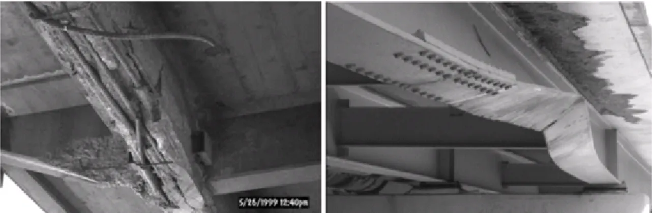
A common structural problem in existing reinforced concrete (RC) highway overpasses is damage to girder elements caused by the passing of trucks exceeding allowable height clearances beneath bridges. These types of impacts are called overheight collisions. Commonly, for RC girders, the impact causes the cover concrete to spall off, exposing reinforcing steel which contributes to the acceleration of corrosion, reducing load carrying capacity and/or the service life of the structure (Figure 3).
Figure 3: Damage to concrete and steel bridge girders resulting from overheight vehicular impacts (Sharma et al., 2008)
Beyond prohibiting access to and rerouting overheight trucks from bridges, one method of mitigating damage due to overheight impact is to apply an energy absorber to the lower lip of bridges to deflect and absorb impact forces. Yang and Qiao (2010) concluded that the core of protective structural design lies in the capacity to absorb energy (or decelerate the projectile) while maintaining the stress/deflection/force transferred to the protected structures below prescribed limits that initiate damage or failure to the protected structures. This converted kinetic energy can be reversible similar to pressure energy in compressible fluids and elastic strain energy in solids or irreversible resembling plastic deformation energy (Alghamdi, 2000).
Sharma et al. (2008) proposed an energy absorbing system or bumper consisting of a stiff guard that distributes the impact energy over a large area and an energy absorbing material (EAM) that dissipates the impact energy, Figure 4.
EM - 001 - 4
Figure 4: Sketch of proposed bumper for bridge girger (Sharma et al., 2008)
Their investigation consisted of impacting a scaled concrete beam (representing a bridge girder) retrofitted with varying types of bumpers with solid steel balls. Four different bumpers were tested: each containing a 3.175 mm layer of stiff guard with modulus of elasticity of 200 GPa with differing types of 50 mm thick high-density flexible polyurethane foam acting as the EAM. The specific material used as stiff guard is not specified. Double-sided duct tape was used to attach the stiff guard and the EAM and to connect the bumper to the concrete beam. The experimental results demonstrated the efficiency of the proposed bridge bumper. When comparing the retrofitted girder to the bare original girder, the maximum tensile stress was reduced 73% (from 1.76 to 0.46 MPa), the maximum compressive stress was reduced 98% (from 17.0 to 0.43 MPa) and the maximum contact force was reduced 96% (from 7.77 to 0.31 kN). The results were validated using the finite element software LS-DYNA. Furthermore, the authors also scaled the results and were thus able to suggest a suitable bridge bumper system for protecting actual concrete bridge girders.
While the system investigated was very effective at decreasing stresses observed during and after impact, a major concern arises regarding its on-field implementation. The system would appear to be relatively heavy, adding eccentric dead loads to the structure. At the very least, designers would have to analyze the retrofitted structure to ensure that global performance was not affected by the retrofit. If the analysis reveals that the structure is not able to safely accommodate the bumper, an additional retrofit would be necessary to implement the system or other alternatives would have to be explored.
In collaboration with the Ohio Department of Transportation, Qiao et al. (2008) developed, designed, analyzed, fabricated, tested and field-installed a double-layer aluminum honeycomb I-Lam (Impact-Laminate) sandwich system to protect girders from overheight vehicle impacts. The I-Lam system consists of two thin face sheets that sandwich two 4 in (102 mm) thick honeycomb layers with crushing strength of 90 and 210 psi (0.62 MPa and 1.45 MPa), respectively. Numerous numerical simulations using the commercially available finite element sofware LS-DYNA were performed upon which the authors provided a recommended thickness of the I-Lam system to adequately protect a concrete girder from varying hypothetical impacts. The bond between a concrete beam (girder) and the collision protection system provided by an epoxy paste anchoring adhesive was evaluated. Also, the crushing of the I-Lam core was studied by experimentally measuring the deformations and strain fields during the crushing process.
As part of their research, Qiao et al. (2008) conducted three full scale impact tests on RC beams: two retrofitted with the I-Lam and one control. A 12 in (305 mm) cubic wooden projectile was used as the impactor with an impacting speed of approximately 72 km/h. Based on qualitative observations and comparisons of the RC beams with and without the I-Lam protection system (Figure 5), the researchers stated that the I-Lam panels are capable of protecting the substrate material from severe damage and are capable of absorbing the impact energy by crushing of the core materials.
EM - 001 - 5
Figure 5: I-Lam girder protection system (circled) before (left) and after (right) being impacted by a wooden cube (Qiao et al., 2008)
The protection system was implemented on a concrete bridge in Delaware, U.S. in the fall of 2006 (Figure 6). Additionally, the researchers also developed and tested a smart impact detection system capable of measuring the level of damage in a concrete girder using piezoceramic (PZT) transducers. The system also has the capability of photographing the offending (impacting) vehicle. A step-by-step construction method for field implementation of the I-Lam system was ultimately proposed.
Figure 6: Field installation of I-Lam panels on concrete bridge (DEL-23-12.99) in Delaware, U.S. (Qiao et al., 2008)
The protection system devised by Qiao et al. (2008) presents certain flaws. It is rather cumbersome and would be difficult to implement in tight spaces or in locations that require architectural aspects and aesthetics to be respected. The system would also likely benefit from a stiff guard such as the one used by Sharma et al. (2008) to distribute the concentrated impact loads over a wider area and reduce damage to the system itself. Like most existing bumper systems, once the system has been impacted, it must be replaced (Figure 5) to ensure ongoing protection.
EM - 001 - 6
A further approach to address the problem of overheight impacts is to elevate the bridge, thus increasing the height clearance and reducing the likelihood of impact. The Georgia Department of Transportation implemented a program to elevate major highway bridges using very short steel columns referred to as pedestals that act as height boosters (Hite et al., 2008) as shown in Figure 7. To install the pedestals, the bridge superstructure is first raised using jacks located at the bent caps supporting the girders. Shims are then inserted until the steel pedestals can be placed between the bent caps and girders. The pedestals transfer loads from the bridge deck to the substructure in the same way as steel rocker bearings. Hite et al. (2008) tested the performance of full-scale steel girder bridges elevated with steel pedestals under quasi-static reverse cyclic loading to evaluate their vulnerability during seismic events. The testing program illustrated that the pedestals dissipate energy and perform adequately during simulated seismic events.
Figure 7: Bridge in Georgia elevated using steel pedestals (Hite et al., 2008)
4. FRP Impact Protection
Significant research has been conducted to investigate the use of composites in protecting concrete from impact forces. Composite materials are formed by the combination of two or more materials to achieve superior physical and chemical properties. Fibre Reinforced Polymers (FRPs) are a type of composite that has emerged in civil engineering applications. The main components of the composite are the fibre and the matrix.
The fibres provide most of the strength and stiffness while the matrix holds the fibres together providing load transfer from the retrofitted structure to the composite (Uddin et al., 2005). There are many types of fibres available to designers and manufacturers of composites: glass fibres which are inexpensive and versatile; carbon fibres which are lightweight and very resistant but more expensive; and aramid fibres, such as Kevlar, which display high energy absorption at failure but are sensitive to creep, moisture and UV light.
The matrix can fall into one of two categories: thermoset or thermoplastic. In a thermosetting resin, the matrix permanently cures or hardens (sets) into a given shape through the application of heat. A polymerization (chemical linking to create long molecular chains) reaction produces the hardening, and the cured material becomes substantially infusible and insoluble (ISIS Canada, 2008). Meanwhile, a thermoplastic resin will soften or melt with the application of heat and will harden upon cooling. The process can be repeated nearly indefinitely.
EM - 001 - 7
The use of externally bonded composite materials such as FRP for the strengthening and retrofitting of existing or new structures is widely adopted in construction practice. This is due to the light weight, high strength, good durability, high fatigue endurance, competitive cost, low thermal coefficient in fibre direction and ease of installation of available composite materials. A number of methods exist for external strengthening of columns using composites. Wrapping is the most common and consists of unidirectional fibre sheets or woven fabric sheets impregnated with polymer resins and wrapped around the column with the fibres principally oriented in the hoop direction. Filament winding is similar to wrapping except that it utilizes continuous fibre strands instead of sheets. Pre-fabricated shell jacketings are built off-site and are usually in the shape of a half-circle or half-rectangle so that they can be opened and placed around deficient columns.
4.1 Thermoset FRP Impact Protection
Jerome and Ross (1997) experimentally investigated the dynamic behavior of beams externally strengthened with varying amounts of FRP on the bottom or tension side subjected to drop-weight impact at the midspan. The beams were small in dimension (7.62 X 7.62 X 76.2 cm), thus no reinforcing steel was provided. The beams with composite wrap on the side faces and bottom (tension) side were also tested. It was consistently observed that the average static peak capacity was less than the dynamic peak capacity. This was attributed to strain-rate effects in the concrete. Also, for beams retrofitted with composites, the dynamic energies were consistently less than the static energies. The addition of external CFRP significantly stiffens the beam, enhancing the beam’s brittle behavior when loaded dynamically. The mechanism by which the beams failed dynamically was similar to that for the static case, shear failure of the concrete at approximately one-quarter of the span from the midspan followed by delamination and peeling of the CFRP. It was concluded that significant gains in terms of load and displacement capacity were achieved by application of the retrofit.
Erki and Meier (1999) investigated concrete beams subjected to impact loads that were retrofitted with CFRP laminates. The results were compared to previous studies where concrete beams were retrofitted with steel plates. A novel approach to induce impact forces was utilized: the impact was produced by raising one end of the beam and dropping it from a certain height. While not representative of any real impact scenarios, the tests performed provided valuable results regarding retrofit detailing. The loading-induced rates of strain ranged from 0.057 s-1 to 0.8 s-1. The amount of CFRP used in the retrofit was such that the total tensile strength provided by the CFRP (200 kN) was approximately equal to that of the steel plates in the previous retrofit scheme (207.5 kN). During testing, energy was first absorbed by a damper located at the point of impact and then by the beams, through concrete cracking and reinforcement yielding. For the beams retrofitted with steel plates, further energy was absorbed by yielding of the plates and by debonding. For the CFRP strengthened beams, the bonded CFRP laminates absorbed energy through the formation of longitudinal cracks in the epoxy layer and by tension failure of the CFRP laminate. It was observed during the explosive failure of the CFRP in tension that many small and jagged fragments of the CFRP projected a significant distance from the beam. The failure was attributed to both debonding and tensile failure: one of the two plies of CFRP would debond, overloading the second which would fail in tension due to overloading. It was concluded that the RC beams externally strengthened for flexure with CFRP laminates performed well under impact loading although energy absorption was less than the beams externally strengthened with steel plates. It was recommended that additional anchoring of the CFRP would increase the impact performance of the beams. Additionally, the mid-span deflections for the beams were predicted using an equation of motion with satisfactory result.
Tang and Saadatmanesh (2003) conducted experiments to study the effects of impact on concrete beams strengthened with FRP laminates. Five beams were tested: two strengthened with Kevlar laminates; two strengthened with carbon laminates; and one control specimen. It was shown that the composite laminates significantly increased the flexural cracking and shear failure strengths of the beam. However, the strength related to diagonal cracking was not significantly affected. Also, vibrations in the beam due to inertial effects were sufficient to cause strains resulting in cracking of the concrete and significant deflections.
EM - 001 - 8
Thermoplastics are relatively new materials that have evolved from conventional thermoset composites. They consist of two elements: a thermoplastic matrix and a reinforcing fibre. One reason that they are not as widely used as thermoset composites is that until recently, the processing and molding of thermoplastics was difficult. In addition, there is concern within the industry as to the sensitivity of this type of composite to heat: thermoplastics can be softened by increases in temperature. It was demonstrated that glass reinforced thermoplastic tested at 204 °C experienced considerable weakening: the longitudinal and transverse strengths were lowered by 85 % and 37 % of their original values, respectively (Milke et al., 1993). A concern is whether thermoplastic FRPs used to retrofit columns to resist impact loads resulting from vehicles or explosive debris would be subjected to similar high temperatures. It is probable that impact generated loads could occur in conjunction with a heightening of temperature. However, thermoplastic composites offer many advantages over thermoset composites: they have a nearly unlimited shelf life, unlike thermoset FRPs that are unstable in their prepregnated form; they do not require a chemical process to cure; they are less brittle; damage is more easily observed; and they offer better impact resistance.
Dixon (1990) conducted research for the aerospace industry providing knowledge on thermoplastics, which can be expanded to other industries. The researcher conducted flat plate impact tests to better understand the spalling failure of carbon fiber reinforced poly ether ether ketone (PEEK) thermoplastic. The rate of loading varied from 36 m/s (no delamination) to an impact velocity of 520 m/s (specimen disintegration). It was concluded from the tests that spall failure in CFRPEEK begins in the matrix rich zone between plies and is brittle in nature. When complete spall separation occurs the spall surface is rough, showing subsurface damage and extensive fiber breakage. It was also observed through electron micrography that crack initiation begins in the matrix.
Uddin et al. (2005) conducted research investigating the reduction in vulnerability of RC columns by retrofitting with a polypropylene (PP) thermoplastic FRP developed for construction purposes. Tests were done to characterize the bond between concrete and PP to develop and implement a method for retrofitting concrete cylinders with glass-reinforced PP (glass/PP) confining jackets. The intent was to determine the energy absorption capacity and ballistic limit and, finally, to replicate ballistic impact results using a FE numerical model. The design and manufacture of the glass/PP composite was completed jointly by researchers at the University of Alabama in Birmingham and the Southern Research Institute (SRI). The result was a thermoplastic composite material produced in pultruded continuous form. It was determined that the bond between the concrete cylinder substrate and the thermoplastic tape was sufficient since the jacket fitted tightly around the cylinder providing adequate confinement during impact events. Stress-strain relationships obtained for the retrofitted cylinders indicate that the thermoplastic jacket increases the ductility response (peak strain was nearly 15 times greater for the retrofitted specimen) without affecting peak load. The authors were also able to accurately model the perforation of concrete plates subjected to missile impacts ranging in speeds from 60 m/s to 121 m/s.
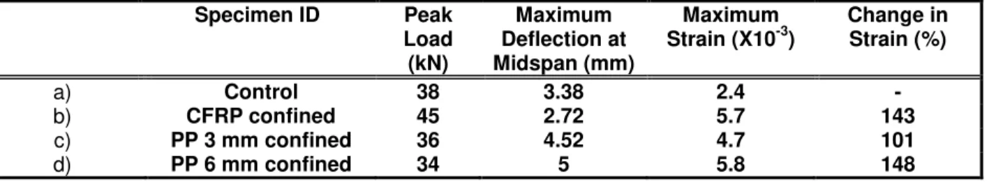
Uddin et al. (2008) further investigated the effectiveness of confining concrete columns with a prefabricated polypropylene (a type of thermoplastic FRP) jacket against impact loading. The thermoplastic composite used in the study was produced in continuous pultruded form to produce a cost-effective split product form of directionally orientated glass fibre in polyurethane (or polypropylene) thermoplastic matrix for a representative bridge column. The work compares the performance of this thermoplastic FRP to CFRP under dynamic loading. First, uniaxial compression tests were conducted on concrete cylinders to evaluate static loading phenomena (Figure 8) followed by impact loading tests on four concrete columns: one control specimen, one CFRP confined and two confined by PP jackets (one of 3 mm thickness, the other of 6 mm thickness). A summary of the results is provided in Table 1. The CFRP confined column experienced the highest peak load due to its higher stiffness relative to other specimens. Notice that the maximum displacement for the 6 mm PP confined column is approximately equal to that of the CFRP confined column. Overall, the study illustrated that prefabricated thermoplastic jackets are a viable solution for impact risk mitigation.
EM - 001 - 9
Figure 8: Failed concrete cylinders retrofitted with thermoplastic wrap (Uddin et al., 2008)
Table 1: Impact test results for tested specimens (Uddin et al., 2008)
Specimen ID Peak Load (kN) Maximum Deflection at Midspan (mm) Maximum Strain (X10-3) Change in Strain (%) a) Control 38 3.38 2.4 - b) CFRP confined 45 2.72 5.7 143 c) PP 3 mm confined 36 4.52 4.7 101 d) PP 6 mm confined 34 5 5.8 148 5. Conclusion
This paper presented research and case studies pertaining to the impact protection of concrete elements. Sacrificial barriers, external systems that aim to reduce impactor velocity, were discussed. The problem of overheight vehicle impacts was discussed and it was found that aside from rerouting traffic or raising the bridge, bumpers made with energy absorbing materials (EAM) that aim to reduce impact energy could be used effectively. Methods used to mitigate overheight vehicle impacts could easily translate to other impact problems. For example, installing bumper systems on the face of overpass columns exposed to oncoming traffic. Also, a review of fibre reinforced polymers (FRPs) and their use in impact protection was also conducted.
While many retrofit strategies exist for mitigating impact damage, they address the problem one-dimensionally. Ideally, an impact protection retrofit would: absorb the shock (reducing impact energy); increase the stiffness (spread the forces over a wider area); be unobtrusive; be lightweight (eliminating the need to analyze the structural performance under additional loads of the retrofit); increase confinement stresses in the structure; and be visually appealing. While comprehensive research is required to better understand thermoplastic FRPs and their performance under impact, they represent a viable solution for the next generation of impact retrofitting material.
6. References
Alghamdi, A. 2001. Collapsible impact energy absorbers: An overview. Thin-Walled Structures. 39(2). 189-213.
EM - 001 - 10
Dixon, D. 1990. Spall failure in a carbon fibre reinforced thermoplastic composite. J Mater Sci Lett. 9(5). 606-8.
Erki M, Meier U. 1999. Impact loading of concrete beams externally strengthened with CFRP laminates. J of composites for construction. 3(3). 117-124.
Hite, M, DesRoches, R, and Leon R. 2008. Full-Scale Tests of Bridge Steel Pedestals. J. Bridge Engrg . 13(5). 483-491
ISIS Canada. 2008. FRP rehabilitation of reinforced concrete structures Design manual No.4 Version 2. ISIS Canada Research Network. Winnipeg, Manitoba, Canada
Jerome, DM and Ross, CA. 1997. Simulation of the dynamic response of concrete beams externally reinforced with carbon-fiber reinforced plastic. Comput Struct. 9;64(5-6). 1129-53.
Larsen, O. 1993. Ship collision with bridges: Structural engineering documents. International association
for bridge and structural engineers. Zurich, Switzerland.
Milke, J and Vizzini, A. 1993. The effects of simulated fire exposure on glass-reinforced thermoplastic materials. J of fire protection engineering. 4(3). 113-124.
Parker, J. 2008. Ship impact protection for Hungerford Bridge, London, UK. Proceedings of the
Institution of Civil Engineers – Structures and Buildings. Thomas Telford for the Institution of Civil
Engineeers. London, England. 162(SB1). 11-19.
Qiao, P, Yang, M, Mosallam, A and Song, G. 2008. An over-height collision protection system of sandwich polymer composites integrated with remote monitoring for concrete bridge girders. Report for
Ohio Department of Transportation and the US Department of Transportation. State Job 134142.
Columbus OH.
Saul, R, Humpf, K and Patsch, A. 2003. Bridge Protection of the Rosario-Victoria Bridge, Argentina. Structural Engineering International. 13(4). 227-231
Sharma, H, Hurlebaus, S and Gardoni P. 2008. Development of a bridge bumper to protect bridge girders from overheight vehicle impacts. Computer aided civil and infrastructure engineering. 23(6). 415-426.
Tang, T and Saadatmanesh, H. 2003. Behavior of concrete beams strengthened with fiber-reinforced polymer laminates under impact loading. J of composites for construction. 7(3). 209-218.
Uddin, N, Farhat, N, Vaidya, U and Serrano-Perez, J. 2005. Vulnerability reduction for bridge piers. University transportation center for Alabama (UTCA) report 03229 2005.
Uddin, N, Purdue, J and Vaidya, U. 2008. Feasibility of thermoplastic composite jackets for bridge impact protection. Journal of aerospace engineering. 21(4). 259-265.
Wuttrich, R, Wekezer, J, Toth, J and Yazdani N. 2001. Retrofit Analysis of Bridge Fender Systems. Journal of Waterway, Port, Coastal, and Ocean Engineering. 127(6). 327-333.
Yang M and Qiao P. 2010. Analysis of cushion systems for impact protection design of bridges against overheight vehicle collision. Int J Impact Eng. 12;37(12). 1220-8.