Shape from polarization in the far IR applied to 3D digitization of transparent objects
by A. Zanzouri Kechiche*, R.Rantoson**, O. Aubreton*, F.Meriaudeau***, and C.Stolz*
* LE2I UMR6306, CNRS, Arts et Métiers, Univ. Bourgogne Franche-Comté, 12 Rue de la fonderie, Le Creusot, 71200, France, abir.kechiche@u-bourgogne.fr
** ISIT UMR 6284, CNRS, Faculté de médecine, 28 place Henri Dunant 63 001 Clermont-Ferrand France ***Centre for Intelligent Signal and Imaging Research (CISIR) Electrical & Electronic Engineering Department University of Technology Petronas 32610 Seri Iskandar, Perak, Malaysia
Abstract
This paper presents an application of “shape from polarization” method in the far Infrared range with applications for three-dimensional reconstruction of transparent objects. Shape from polarization is a recent application of more general polarization imaging technique having the aim to digitize the shape of the observed object. The principle is to evaluate the normal on each observed point followed by an integration procedure. The technique is well developed in the visible domain, but not in the far infrared domain due to the requirement of telecentric optics. We propose here a complete setup in the 8-13 micrometer spectral band with an appropriate source and a reconstruction method including the pinhole camera model in order to use standard optics for the camera. We present primary results of three-dimensional digitization of transparent objects.
Keywords: Polarization, thermal imaging, transparent objects, long wave infrared and three-dimensional
digitization
1. State of the art
Recovering three-dimensional surface shape of objects, remains an important research area of computer vision. However, when dealing with the inspection of transparent or highly reflective surfaces like mirror, standard solutions are not available yet. Referring to these non “Lambertian” surfaces, Ihrke et al [1] published an exhaustive survey which was recently completed by Meriaudeau et al.[2]for transparent objects.
Among the recent works, approaches such as “scanning from heating” [3], where the three-dimensional data is reconstructed from a heat pattern visualized with a calibrated IR camera or “shape from induced fluorescence” [4] where the three-dimensional reconstruction takes place thanks to a generated visible pattern induced by florescence onto the object surface, appear to be very promising for three-dimensional inspection with potential adaptation for transparent as well as specular objects.
The shape from polarization technique, based on the analysis of polarimetric property of the light reflected from the object, is also well adapted for non “lambertian” surfaces. This is an unconventional approach because it does not rely on the tradionnaly used parameter in machine vision such as the intensity and wavelength. A standard camera model limited by brightness and hue is not enough to measure the polarization parameters.
In this paper, we used the shape from polarization method in the far infrared band. This spectral band corresponds to a part of the spectrum where transparent materials like glass and some plastics appear opaque. Since the pioneer works of Wolff [5] on polarization imaging, recent extensions have been made possible by active lightings systems [6], multispectral approach [7] and infrared imaging. In the field of remote sensing Middle IR band is then used for material detection and separation [8].The last example used the near IR band [9] in order to build a depth map of the outdoor environment. This brings new interest in polarization imaging techniques.
2. Proposed Method
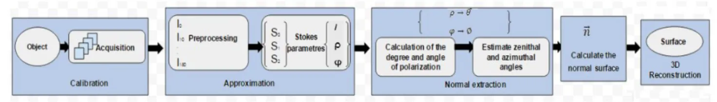
The acquisition and reconstruction procedure is as follows (Figure1): acquisition of an image sequence by manually rotating a linear polarizer with an angle α, evaluation of the Stokes parameters, estimation of the normals field and of the 3D surface.
Fig. 1. Schematic summary of the proposed reconstruction process
Based on the fact that after reflection, a non-polarized light wave becomes partially linearly polarized, the aim of the shape from polarization is to measure the normal at each observed point and then to obtain the whole surface by integration of the normals field as in shape shading techniques[10].
A partially polarized wave may be defined by three-parameters which are: the light intensity , the degree of polarization ρ and the angle of polarization φ. Each of these parameters can also be defined with the stokes parameters , and [11]. Since no ellipticity is measured, a partial Stokes sensor with a rotative polarizer (figure 1) or equivalent with electro-optics components is sufficient. The intensity of the wave impinging on the camera is given by Eq.1 define .
(1) ρ and φ are respectively linked to the zenithal angle θ and to the azimuthal angle ϕ through the Snell-Descartes relation. These measurements enable to infer the normal at each point as recalled by Eq.2 define
and the gradient p and q.
(2) 3. Experimental Set-up
The common procedure for evaluating the polarization parameters begins by evaluating the three stokes parameters. This requires a sequence of images; each image is obtained after rotating the polarizer with a constant step of 10 degrees (α), and then perform a least square fitting and finally evaluate the degree and angle of polarization. However, as pointed out earlier by Miyazaki [12] and Morel [6], evaluation of by these measures is not straightforward since both of them provides two candidates. That’s why the use of an active light source was introduced by Morel [6] who calculates an image mask Iquad in order to properly solve the ambiguity for the azimuthal angle in the case of metallic surfaces. Concerning the zenithal angle, Miyazaki [13] introduced a multispectral technique considering visible and IR measurement. This needs two different setups, one in the visible and one in the IR, implying either registration or a cumbersome optical system. Also one of the main constraints of standard shape from polarization setups is the use of orthographic projection that is physically realized by telecentric optics. To overcome these two problems, we propose an active shape from polarization experiment in the far Infrared band.
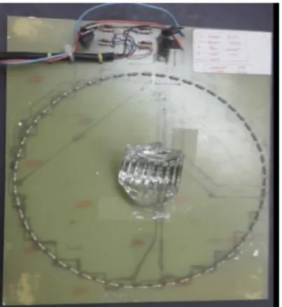
Our systems includes (Figure 2) a thermal camera (Flir A645) of [8 μm -13 μm] range, of 640x480 resolution, a non telecentric 24.5mm focal lens, a manual rotating (ZnSe) polarizer of [1 μm-15 μm] range with an orientation angle α. Also a specific dome (generating the quadrant active IR lighting) is composed of two pieces: a metallic cover which top is holed to place the camera, and a slab of 56 resistors (Figure 3) (12 Ohms and 0.25W each) supplied by a voltage of 12V for each quadrant illumination. The temperature of each resistor is constant, ~60 degrees Celsius, during the acquisitions, corresponding to a maximum radiation of 8.7 μm according to Wien’s law.
Fig. 3.Lighting system in the IR made of resistors and which can be turned on by quadrants
Since we use the standard lens of the camera, the projection model is now the perspective model, so we choose to be in conditions as close as possible to be original orthographic projection. The pinhole lens model is recalled by Eq.3 for the transformation between 3D coordinates and the image coordinates where and characterize the focal distance, the position of the optic center of the camera and is the scale factor.
(3)
In this model all the rays are converging to the optical center of the camera. That’s why we use a relaxed perspective model where the distance camera-object is sufficiently far from the camera [14]. We use the virtual plane at this distance as the basis of the reconstruction.
The method requires to calibrate the camera in order to estimate the appropriate distance . We used the well-known Zhang-Bouguet method [15]; it requires the use of a checkerboard in order to acquire a sequence of images at different depths and orientations that permits to extract a set of world points necessary for estimating the intrinsic parameters. In our case, the checkerboard was realized with the etching technology of electronic board, so half of the squares are in cupper and the order in the resin material each of them having a different emissivity in the Infrared (Figure 3a). Due to the high sensitivity of the camera, no important heating is needed on the checkerboard as shown by the raw thermal image of (figure 3b). Notice that for better accuracy in the future processing, all the images are pre-processed (Figure 3c) to grayscale to have higher contrast.
(a) (b) (c)
Fig. 3. a) View of the checkerboard made of two materials of different emissivity in IR b) Raw thermal image c) Processed view of the thremal image in graylevels.
Once this calibration is done, we can determine the appropriate scale factor by using two reference points: one on the object and one on the support of the object. is defined as the mean distance between the reference points multiplied by the scale factor . In our experiments was estimated to 300 mm.
The other consequence of the perspective model will be the non-regularity of the coordinates grid compared to the former orthographic model. That’s why we adapted the integration method by using the successive Over Relaxation approach [16].
4. Result
To sum up, the acquisition and reconstruction procedure is as follows: acquisition of the image sequence by rotating the polarizer, acquisition of the mask image [6] by sequentially powering the resistors and evaluation of the Stokes parameters with verification of their accuracy in order to remove noisy data points. The criterion evaluates the physical admissibility of the parameters, , completed by the comparison between the measured intensity by the sensor and the approximated intensity : we consider the relative error between and , the sign of the product of their respective derivative and the relative error of these derivatives [14].
This admissibility criterion is visualized as binary image where black pixels satisfy the criterion. If more than 80% of pixels are satisfactory (Figure 4b), we calculate the polarization parameters (Figure 5a and Figure 5b), the zenithal and azimuthal angles, then the normals field (Figure 6) and at the end the 3D shape.
Fig 4. a) Glass object b) Quality map for the evaluated Stokes parameters (black pixels are good)
Fig. 6. The normals field
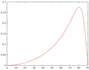
Furthermore, the dispersion and absorption of the far IR light is due to impurities in the glass matrix. This implies a complex value of the refraction index that shifts the value of the Brewster angle to high values, enabling to infer the correct value of the zenithal angle θ from the degree of polarization for surface with angle ranging from 0 to maximum values close to 80°. However, even for the Brewster angle, the degree of polarization is less than 1. This can be compensated by introducing a pseudo-index, where n is the real index and k the coefficient of extinction of the material being studied. This value has to be estimated empirically for each studied sample. This is done by choosing an index so that the estimated value of the Brewster angle matches the maximum value of the measured degree of polarization. For example, the curve of Figure .7 corresponds to a pseudo-index estimated to 1.6+3.5i for the object presented in Figure 4.a. The value of 0.27 at the Brewster angle is closed to the measured degree of polarization of 0.24 (Figure 5.a). It has the advantage to take care of the noise and finely tune the final shape.
Our experiments were first conducted with the glass object of Figure 4.a that is reconstructed by following the previous steps. As we see in Figure 8.a and Figure 8.b the reconstructed shape is in close agreements with the observed object (Figure4.a).
(a) (b)
Fig.4. 3D reconstruction of the tested glass object (a) matlab and (b) rapidform result
5. Conclusion
In conclusion, we presented an extension of the shape from polarization within the long Infrared range. The active lighting setup as well as the use of long IR range enables us to remove the ambiguities on both the zenithal angle and azimuthal angle. Also the extension of the reconstruction model by using the perspective lens model permits us to avoid the use of costly telecentric lens. Promising preliminary results were obtained and further experiments are still being carried out to further validate the accuracy of the system. A second ring of resistors can then be added to the IR source in order to apply a multispectral approach [17].
REFERENCES
[1] I. Ihrke, K. N. Kutulakos, H. P. A. Lensch, M. Magnor, and W. Heidrich, "Transparent and Specular Object Reconstruction", Computer Graphics Forum 29, 2400-2426 (2010).
[2] F. Meriaudeau, R. Rantoson, D. Fofi, and C. Stolz, "Review and comparison of Non Conventional Imaging Systems for 3D Digitization of transparent objects", Journal of Electronic Imaging 21, 021105 (2012).
[3] F. Meriaudeau, L. A. Sanchez-Secades, G. Eren, A. Erçil, F. Truchetet, O. Aubreton, and D. Fofi, "3D Scanning of Non-Opaque Objects by means of Infrared Imaging", IEEE Transaction on Instrumentation and Measurement 59 2898-2906 (2010).
[4] R. Rantoson, C. Stolz, D. Fofi, and F. Meriaudeau, "Optimization of transparent objects digitization from visible fluorescence ultraviolet induced", Opt. Eng. 51, 033601-033601 to 033601-033610 (2012).
[5] L. B. Wolff, "Polarization vision: a new sensory approach to image understanding", Image and Vision computing 15, 81-93 (1997).
[6] O. Morel, C. Stolz, F. Meriaudeau, and P. Gorria, "Active Lighting Applied to 3D Reconstruction of Specular Metallic Surfaces by Polarization Imaging", Appl. Opt. 45, 4062-4068 (2006).
[7] M. Ferraton, C. Stolz, and F. Mériaudeau, "Optimization of a polarization imaging system for 3D measurements of transparent objects", Opt. Express 17, 21077-21082 (2009).
[8] F. Cremer, W. d. Jong, K. Schutte, W.-J. Liao, and B. A. Baertlein, "Detectability of surfacelaid landmines with a polarimetric IR sensor," in Detection and Remediation Technologies for Mines and Minelike Targets VIII, (SPIE, 2003).
[9] F. A. Sadjadi, "Passive three-dimensional imaging using polarimetric diversity", Opt. Lett. 32, 229-231 (2007). [10] R. Zhang, P. S. Tsai, J. E. Cryer, and M. Shah, "Shape from shading, A survey", IEEE Trans. Pattern Anal.
Mach. Intell. 21, 690-796 (1999).
[11] D. L. Goldstein, Polarized light second Edition (Optical Engineering) (CRC, 2003), p. 680.
[12] D. Miyazaki, M. Kagesawa, and K. Ikeuchi, "Determining Shapes of Transparent Objects from Two Polarization Images," in IAPR, (IEEE, 2002), 26-31.
[13] D. Miyazaki, M. Saito, Y. Sato, and K. Ikecuhi, "Determining Surface Orientations of transparent objects on polarization degrees in visible and infrared wavelength", J. Opt. Soc. Am. A 19, 687-694 (2002).
[14] R. Rantoson, C. Stolz, D. Fofi, and F. Meriaudeau, "3D Reconstruction by polarimetric imaging method based on perspective model," in Europe Optical Metrology, (SPIE, 2009).
[15] Z. Zhang, "Flexible camera calibration by viewing a plane from unknown orientations," in International Conference on Computer Vision, (IEEE, 1999), 666.
[16] W. Press, S. Teukolsky, W. Vetterling, and B. Flannery, Numerical Recipes in C++, 3rd edition ed. (Cambridge University Press, 2007).
[17] C. Stolz, M. Ferraton, and F. Meriaudeau, "Shape from polarization: a method for solving zenithal angle ambiguity", Opt. Lett. 37(2012).