Publisher’s version / Version de l'éditeur:
Insight magazine, 53, 2, pp. 316-320, 2011-06-01
READ THESE TERMS AND CONDITIONS CAREFULLY BEFORE USING THIS WEBSITE.
https://nrc-publications.canada.ca/eng/copyright
Vous avez des questions? Nous pouvons vous aider. Pour communiquer directement avec un auteur, consultez la
première page de la revue dans laquelle son article a été publié afin de trouver ses coordonnées. Si vous n’arrivez pas à les repérer, communiquez avec nous à PublicationsArchive-ArchivesPublications@nrc-cnrc.gc.ca.
Questions? Contact the NRC Publications Archive team at
PublicationsArchive-ArchivesPublications@nrc-cnrc.gc.ca. If you wish to email the authors directly, please see the first page of the publication for their contact information.
NRC Publications Archive
Archives des publications du CNRC
This publication could be one of several versions: author’s original, accepted manuscript or the publisher’s version. / La version de cette publication peut être l’une des suivantes : la version prépublication de l’auteur, la version acceptée du manuscrit ou la version de l’éditeur.
For the publisher’s version, please access the DOI link below./ Pour consulter la version de l’éditeur, utilisez le lien DOI ci-dessous.
https://doi.org/10.1784/insi.2011.53.6.316
Access and use of this website and the material on it are subject to the Terms and Conditions set forth at
Flexible ultrasonic transducer arrays for health monitoring of an aircraft
component
Liu, W.-L.; Jen, C.-K.; Wu, K.-T.; Kobayashi, M.; Mrad, N.
https://publications-cnrc.canada.ca/fra/droits
L’accès à ce site Web et l’utilisation de son contenu sont assujettis aux conditions présentées dans le site LISEZ CES CONDITIONS ATTENTIVEMENT AVANT D’UTILISER CE SITE WEB.
NRC Publications Record / Notice d'Archives des publications de CNRC:
https://nrc-publications.canada.ca/eng/view/object/?id=7d1c4026-6f00-41a8-b1c3-f261bb5ce12f https://publications-cnrc.canada.ca/fra/voir/objet/?id=7d1c4026-6f00-41a8-b1c3-f261bb5ce12f
1
Flexible ultrasonic transducer arrays for health monitoring of an
aircraft component
W.-L. Liu
a, C.-K. Jen
b, K.-T. Wu
b, M. Kobayashi
b, and N. Mrad
ca
Department of Electrical & Computer Engineering, McGill Univ., Montreal, QC Canada H3A 2A7;
b
Industrial Materials Institute, NRCC, 75 Mortagne boul., Boucherville, QC Canada J4B 6Y4;
c
Deptartment of National Defence, Defence R&D Canada/Air Vehicles Research Section, National
Defence Headquarters, Ottawa, ON Canada K1A 0K2
ABSTRACT
A damage detection capability of the flexible ultrasonic transducer (FUT) array bonded onto a planar and a curved surface are presented. The piezoelectric lead zirconate titanate composite (PZT-c) film FUT arrays are fabricated on the 75 µm titanium membrane substrate using a sol-gel spray technique. The test article was a complex aluminum component that is representative of aircraft structural complexity. Room temperature curable adhesive is used as the bonding material and ultrasonic couplant between the FUT and the test article. The glue has been successfully tested in the temperature range of -80 °C to 100 °C, which covers the sensor operating temperatures commonly required for aircraft structures. For a planar surface the selected FUT arrays were able to detect the fasteners and the 2.54 mm long electrical discharge machining (EDM) notch up to the distance of 176 mm with sufficient signal to noise ratio. The pulse-echo measurements obtained by the FUT array were compared with the ones using a commercial 10 MHz ultrasonic transducer (UT). The results showed that the performance of the FUT array was as good as the commercial UT. Another FUT array was bonded onto a curved surface of the test article using the same adhesive. No measurement using commercial UTs was taken on the curved surface because restricted access around this area did not allow such measurement. The pulse-echo measurements confirmed the detection of EDM notches of 2.54 mm long and 1.27 mm long. The experimental results demonstrated the potential of FUT arrays for aircraft structural health monitoring.
2
Keywords: Flexible ultrasonic transducer array, structural health monitoring, nondestructive testing.
1.
INTRODUCTION
For several decades, civil and military aircraft operators around the world have encountered increased maintenance costs due to their aging fleets (1). As a consequence, they continue to seeking ways to reduce the fleet maintenance cost while
meeting airworthiness requirements. Structural health monitoring (SHM) is potentially a cost effective emerging area of technology that could enable condition-based maintenance in-lieu of the traditional schedule-based maintenance (2,3).
Among the various SHM techniques (4-6), such as visual inspection, radiographic inspection, liquid penetrant inspection,
eddy current inspection, ultrasonic inspection, etc, the ultrasonic inspection is widely used in aircraft maintenance programs for detection of corrosion, subsurface defects or flaws in composite structures (1).
It has been demonstrated that various types of ultrasonic waves have the ability of detecting damages in the materials (2, 5,
7-9)
. In order to use this active sensing approach in aircraft SHM applications, one important requirement is that the ultrasonic transducers (UTs) are light to avoid introducing too much weight on aircraft. It is also required that the UTs have small physical size as many structures on the aircraft have restricted access. However, conventional UTs have the following limitations for SHM of aircraft components; (a) need of couplant, (b) lack of integration ability for curved surface applications, (c) difficulty for use at temperatures above 60°C. As a result, conventional UTs are not suitable for many SHM applications (10).
Integrated UTs (IUTs) (11) and flexible UTs (FUTs) (12) would satisfy the above mentioned basic requirements. In our past
research, integrated ultrasonic transducers (IUTs) were used on bare aluminum (Al) plates to demonstrate this capability for crack growth monitoring (13). This capability demonstration did not address aircraft complex environment, such as
accessibility, temperature variation, instrumentation etc. In this presented study, simple and complex test articles (planar and the curved structures) are used to demonstrate some of the challenges that may be encountered while implementing
3
SHM solutions for aircraft as well as the suitability of the use of FUTs for such application. These FUT are deemed suitable and of choice due in part to their on-site instrumentation flexibility.
2.
EXPERIMENT SETUP
2.1 Test article
A complex aluminum (Al) structural component, representative of aircraft structural complexity, was developed and damaged in the form of artificially induced electrical discharge machining (EDM) notches at selected fastener locations as shown in Figure 1. This component was made available, by Defense Research and Development Canada (DRDC), for the evaluation of FUT in damage detection in complex environment. Several EDM notches were introduced in the 6.35 mm thick Al plate (Fig. 1). Notches 1, 3, and 4 are of 2.54 mm long and notches 2, 5, and 6 are of 1.27 mm long. The FUT array is to be bonded on the planar and curved surfaces, as indicated in Fig. 1. Table 1 summarizes the length of the EDM notches and the distance of the notches to the FUT.
4
Table 1. Distance of notches to FUT array.
Notch
1
2
3
4
5
6
Length (mm)
2.54
1.27
2.54
2.54
1.27
1.27
Distance (mm)
15
48
117
135
158
176
2.2 Instruments and equipments
The lead-zirconate-titanate composite (PZT-c) film was fabricated on a 75 µm titanium doubler (Ti) membrane and it realized FUT. In this study the fabrication of the FUT arrays based on a sol-gel spray technique consists of six main steps
(11-13)
: (1) preparing a high dielectric constant PZT sol-gel solution, (2) ball milling the piezoelectric PZT powders in a PZT sol-gel solution to submicron sizes, (3) sensor spraying using slurries from steps (1) and (2) to produce a film with thicknesses of between 5 and 20 µm, (4) heat treating to produce a solid PZT-c thick film, (5) Corona poling to obtain piezoelectricity, and (6) silver paste painting or colloidal silver spray with a mask to deposit top electrodes. Steps (3) and (4) are performed multiple times to produce optimal film thicknesses for specified ultrasonic operating frequencies. By this method, miniature FUT arrays could be realized with facile (14). A typical value of d33 measured for the PZT-c film
on steel substrates is 30 10-12 m/V, the Kt 0.2, the relative dielectric constant 320, the density 4400 kg/m3 and the L wave velocity 2200 m/s. It is noted that due to lower oxidation on Ti during the heat treatments, the ultrasonic performance of the FUT made on Ti membrane is a few dBs stronger than that made on stainless steel membrane. PZT-c FUTs on Ti doubler membrane showed comparable signal strength with commercial UTs, in addition to sufficient SNR, broadband frequency characteristic, flexibility that enabled to install a pipe with 26.6 mm outer diameter, and installation facility. Furthermore, such FUTs made of PZT-c films had survived thermal cycles between -80°C and 100°C (15).
Therefore, PZT-c FUTs with Ti membrane could be suitable for aircraft SHM applications.
Before the PZT-c FUTs with Ti membrane were bonded on the planar surface at selected locations, a commercial ultrasonic transducer (UT) Panametrics V129-10MHz-0.125 was used to form a reference so that the measurements taken using the FUTs may be evaluated in terms of performance.
5
2.3 Radiographic inspection
A radiographic inspection was conducted on the test article in order to confirm the locations of the artificially induced EDM notches. The radiographic films and a zoomed-in view are shown in Fig. 2. During the inspection, the X-ray probe needed to be tilted at various angles in order to detect more EDM notches. In addition, it is noted that only the 2.54 mm long EDM notches were identified using this NDT technique. These results will be compared with the ultrasonic technique described in the following sections.
Figure 2. Radiographic inspection of the test article.
3.
FUT ARRAY BONDED ON PLANAR SURFACE
Before bonding the FUT array onto the planar surface, pulse-echo measurements using a commercial UT Panametrics V129-10MHz-0.125 were taken at the same locations of that of the FUT. One FUT was bonded onto the planar surface, as indicated in Fig. 3, using commercial room temperature curable adhesive. In this investigation, the pulse-echo measurements taken using FUT A and FUT B were compared with the ones using the commercial ultrasonic transducer. The distance from the bonding surface to the EDM notches can be found in Fig. 1.
6
Figure 3. FUT array bonded on planar surface.
Table 2 summarizes the distance of the bonded FUT to the EDM notches and their associated expected time delay. The plate acoustic wave (PAW) group velocity of 6234 m/s used for calculation of time delay was obtained by dividing the round trip distance 1020 mm, from the bonded FUT to the opposite edge, by the time difference of the two strongest consecutive echoes reflected from the opposite edge of the structure.
Table 2. Distance of FUT array to notches and expected time delay
Notch
1
2
3
4
5
6
Distance (mm)
15
48
117
135
158
176
Expected Time
Delay (µs)
4.81
15.40
37.54
43.31
50.69
56.46
The center frequency of the FUT is 10 MHz. The signals obtained from both the commercial ultrasonic transducer V129 and the FUT using the pulse-echo technique were compared at FUT locations A and B, as shown in Fig. 3. All top electrodes have an identical dimension of 3 mm by 5 mm. The pulser/receiver settings used to obtain signals for both commercial ultrasonic transducer V129 and the FUT were the same.
7
Figure 4 shows the ultrasonic signals, filtered using a band-pass filter 5- 11 MHz and measured at FUT location A. EN2,
EN3, and EN6 noted in Fig. 4 may be the echoes from EDM notches 2, 3, and 6, shown in Fig. 3, respectively. The actual
time delays of the echoes agree well with the calculated values of Table 2. ER1 and ER2 are the echoes reflected from
fastener R1 and R2, which are 82 mm and 94 mm, respectively, from the FUT bonded edge, shown in Fig. 3. It is observed that the signal-to-noise ratio (SNR) of the measurements using the FUT was generally higher than the ones using the commercial ultrasonic transducer V129. Although the EDM notches and fasteners are not in the normal incidence path of FUT A, these features may still be detected due to the fact that ultrasound beam width increases over distance. However, these damage detections cannot be confirmed without being compared with the baseline signals taken before EDM notches were introduced.
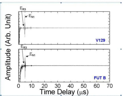
Another set of measurements was taken at FUT location B, shown in Fig. 5. FUT location B is aligned with EDM notch 1. The unfiltered signals are shown in Fig. 5. EN1 represents the echo reflected by EDM notch 1 and ER3 the echo
reflected by fastener R3, as shown in Fig. 3. It is observed that other obstacles that were detected at FUT location A were not detected at FUT location B. This could have been caused by the blockage of wave energy when reflected by EDM notch 1.
8
Figure 5. Signals measured using FUT B and commercial 10 MHz UT at the same location.
4.
FUT ARRAY BONDED ON CURVED SURFACE
It is noted that the planar surface described in the last section may not be accessible on actual aircraft structures. As a result, another approach involving an accessible surface needed to be considered. In this section, the FUT array was bonded onto the curved surface indicated in Fig. 1 and Fig. 6. Under such condition, it may be extremely difficult to use commercial UTs on these small accessible curved surfaces. Here, damage detection capability of the FUT array bonded on curved surface was investigated. Measurements using conventional UT on this curved surface were not taken as the restricted access of 6 mm does not allow placing a conventional UT. In addition, conventional UTs normally are not as effective on a curved surface.
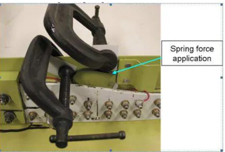
Figure 6 shows the dimension of the FUT to be used. The centre frequency of the FUT is 10 MHz. As soon as the bonding surfaces were cleaned, two pieces of the FUT shown in Fig. 6 were bonded onto the curved surface using commercial room temperature curable adhesive. The curing time of the adhesive is 24 hours at room temperature. The jig and the elastic thin steel plate shown in Fig. 7 were necessary for spring force application in order to achieve uniform
9
pressure across the curved surface during the curing process. Such room temperature curable adhesive has been successfully tested in the temperature range of -80 °C to 100 °C, which covers the common aircraft operating temperatures.
Once the adhesive was completely cured, colloidal silver was painted as top electrodes on the piezoelectric film in array configuration using a paper mask shown in Fig. 8. Colloidal silver was used because it is easier to manipulate using a brush. The top electrodes having 1 mm width and 1 mm spacing enabled measurements with greater precision. Fig. 9 shows the FUT array bonded on the curved surface. Each top electrode represents a fully functional UT.
Figure 6. Curved surface and FUT.
10
Figure 8. Mask used for top electrode fabrication of FUT array.
Figure. 9. FUT array bonded on the curved surface.
In order to illustrate the relative positions of the top electrodes in array configuration to the EDM notches and fasteners, a cross section (X-ray image) is shown in Fig. 10. Since the distances from the FUTs to the fasteners or EDM notches cannot be measured physically, they were measured using the X-ray image instead. However, these measurements may not be very precise as the X-ray image may have been shot slightly off the normal angle. It is noted that two EDM notches, 2.54 mm long notch A and 1.27 mm long notch B, were targeted for detection by the bonded FUTs.
11
Fig. 10. Cross section (X-ray image) of the FUT on the curved surface.
The pulse-echo measurements using FUT 1 and FUT 6, shown in Fig. 11, along with the distances 33.7 mm and 5.1 mm, shown in Fig. 10 respectively, were used to obtain the time delay caused by the measurement equipments and the PAW group velocity through simple algebraic computations. The resulting time delay was 1.07 µs and the group velocity was 6335 m/s. FUT 1 and FUT 6 were chosen because the line of sights of these FUTs directly intercepts the fasteners. FUT 13, 14, and 15 were selected for studying possible detection of EDM notch A. Fig. 12 shows the pulse-echo measurements taken using these three FUTs.
Based on the raw signals shown in Fig. 12, it is difficult to identify the echo from EDM notch A. Therefore, it is necessary to obtain background knowledge of the expected time delay of the echo from EDM notch A. The measured time delays obtained from FUT 13, 14, and 15, and the calculated time delays based on the measured distances and the wave velocity obtained previously are summarized in Table 3. The largest difference between the expected time delay and the measured time delay is 0.34 µs, which is translated to 1.08 mm one-way distance. Considering the measuring technique, the 1.08 mm difference is a reasonable measurement error. The results indicated that the small echoes
12
identified in red rectangles shown in Fig. 12 may be due to EDM notch A. Despite the short distance between the FUTs and EDM notch A, the echoes are weak because the ultrasonic beam is not at the normal angle to the notch, as seen in Fig. 10.
Fig. 11. Pulse-echo measurements taken using FUT 1 and FUT 6.
13
Table 3. Distance from FUT array to EDM notch A and associated time delay
Pulse-echo at
FUT No.
Distance to the
tip of EDM
notch (mm)
Expected time
delay of echo
(µs)
– (A)
Measured time
delay of echo
(µs)
– (B)
Difference
between (A)
and (B) (µs)
13
11.72
2.92
2.60
0.32
14
12.46
3.04
2.70
0.34
15
14.65
3.38
3.2
0.18
Referring to Fig. 10, EDM notch B is in the line of sight of FUT 24 and FUT 25. However, it was expected that little reflected ultrasonic wave energy was received by FUT 24 and FUT 25 because the incident wave angle is very large. Thus, comparisons of the expected time delays and the measured time delays were required in order to validate the measurements. Fig. 13 shows the pulse-echo measurements taken using FUT 24 and FUT 25 indicated in Fig. 10. The distances from FUT 24 and FUT 25 to EDM notch B and associated time delays are listed in Table 4. The largest difference between the expected time delay and the measured time delay is 0.37 µs, which is translated to 1.17 mm one-way distance. Again, this difference is a reasonable measurement error. The comparison indicated that the echoes identified in red rectangles in Fig. 13 may be reflected by EDM notch B.
14
Table 4. Distance from FUT array to EDM notch B and associated time delay.
Pulse-echo
at FUT
No.
Distance to the
tip of EDM
notch (mm)
Expected time
delay of echo
(µs)
– (A)
Measured time
delay of echo
(µs)
– (B)
Difference
between (A)
and (B) (µs)
24
8.79
2.46
2.30
0.16
25
9.52
2.57
2.20
0.37
5.
SUMMARY
In this study, damage detection capability of a flexible ultrasonic transducer (FUT) array bonded onto a planar surface and a curved surface was studied. The previously developed integrated ultrasonic transducer (IUT) was not used in this current study due to it lack of instrumentation flexibility (in-situ application and thermal treatment requirement). The test article used was a complex aluminum (Al) component that is representative of aircraft structural complexity. Several notches of different sizes were introduced in the test article in order to simulate the fatigue crack typically found in this type of structure.
The FUT array, fabricated on 75 µm Ti substrate, was bonded onto a planar surface of the test article using commercial room temperature curable adhesive. Such room temperature curable adhesive has been successfully tested in the temperature range of -80 °C to 100 °C, which covers operating temperatures commonly observed in aircraft environment. The FUTs were able to detect fasteners and several notches of up to a distance of 176 mm with sufficient signal to noise ratio. The pulse-echo measurements obtained using the FUT arrays were compared to those obtained with a commercial 10 MHz ultrasonic transducer (UT). Obtained results showed that the performance of the FUT array was as good as the commercial UT. Nonetheless, this is the ideal scenario as the ultrasound beam is almost at normal angle to the induced damage.
Additionally, another FUT array was bonded onto a curved surface of the same test article using the same adhesive. No measurements using commercial UT was conducted due to article complexity and restricted access. The pulse-echo measurements using the FUTs confirmed detection of EDM notches of 2.54 mm long and 1.27 mm long, based on the expected time delay. Damage detection for this scenario is particularly challenging due to the fact that the ultrasound beam is at large incidence angle to the notches and the majority of the wave energy reflects away from the FUTs.
15
Both planar surface bonded FUT and curved surface bonded FUT arrays successfully demonstrated their potential in damage detection. In addition, experimental results confirmed the potential of the use of FUT array as an additional capability in aircraft structural health monitoring.
ACKNOWLEDGEMENTS
Financial support from the Natural Sciences and Engineering Research Council of Canada and technical supports of Zhigang Sun and Harold Héberd are acknowledged.
16
REFERENCES
1. C Boller, ‘Ways and options for aircraft structural health management’, Smart Materials and Structures, Vol 10, pp 432-440, 2001.
2. J-B Ihn and F-K Chang, ‘Ultrasonic non-destructive evaluation for structure health monitoring: built-in diagnostics for hot-spot monitoring in metallic and composite structures’, Ultrasonic Nondestructive Evaluation Engineering and Biological Material Characterization, edited by T Kundu, CRC Press, Chapter 9, 2004.
3. R P Dalton, P Cawley and M J S Lowe, ‘The potential of guided waves for monitoring large areas of metallic aircraft structure’, J. Nondestructive Evaluation, Vol 20, pp 29-46, 2001.
4. C Hellier, ‘Handbook of Nondestructive Evaluation’, McGraw-Hill, 2001.
5. ASM International Handbook Committee, ‘Nondestructive evaluation and quality control’, ASM International, 1989.
6. A S Birks, R E Green and G Podnar, ‘Robotic assistants foraircraft inspections’, Instrumentation & Measurement Magagine, Vol 1, No 1, pp 16-30, 1998.
7. M G Silk, ‘The determination of crack penetration using ultrasonic surface waves’, NDT International, Vol 9, No 6, pp 359-365, 2008.
8. J K Na, J L Blackshire and S Kuhr, ’Design, fabrication, and characterization of single-element interdigital transducers for NDT applications’, Sensors and Actiators A: Physical, Vol 148, No 2, pp 359-365, 2008.
9. Z Chang and A Mal, ‘Scattering of Lamb waves from a rivet hole with edge cracks’, Mechanics of Materials, Vol 31, No 3, pp 197-204, 1999.
10. O Roy, S Mahaut and S Chatillon, ‘Ultrasonic inspection of complex geometry component specimen with a smart flexible contact phased array transducer: modeling and application’, Proceedings of IEEE Ultrasonics Symposium, Vol 1, pp 763-766, 2000.
11. M Kobayashi, C-K Jen, J F Moison, N Mrad and S B Nguyen, ‘Integrated ultrasonic transducers made by the sol-gel spray technique for structural health monitoring’, Smart Materials and Structures, Vol 16, No 2, pp 317-322, 2007. 12. M Kobayashi, C-K Jen and D Lévesque, ‘Flexible ultrasonic transducers’, IEEE Transactions on Ultrasonics,
17
13. K-T Wu, M Kobayashi and C-K Jen, ‘Integrated high temperature piezoelectric plate acoustic waves transducers using mode conversion’, IEEE Transactions on Ultrasonics, Ferroelectrics, and Frequency Control, Vol 56, pp 1218-1224, 2009.
14. J-L Shih, K-T Wu, C-K Jen and J-W Liaw, ‘Development and ultrasonic measurements of 150°C 116 flexible transducer array’, Proceedings of Symposium on Ultrasonic Electronics, pp 75-76, 2010.
15. J-L Shih, M Kobayashi and C-K Jen, ‘Flexible metallic ultrasonic transducers for nondestructive testing of pipes at high temperatures’, IEEE Transactions on Ultrasonics, Ferroelectrics, and Frequency Control, Vol 57, No 9, pp 2103-2110, 2010.