Publisher’s version / Version de l'éditeur:
Vous avez des questions? Nous pouvons vous aider. Pour communiquer directement avec un auteur, consultez la première page de la revue dans laquelle son article a été publié afin de trouver ses coordonnées. Si vous n’arrivez pas à les repérer, communiquez avec nous à [email protected].
Questions? Contact the NRC Publications Archive team at
[email protected]. If you wish to email the authors directly, please see the first page of the publication for their contact information.
https://publications-cnrc.canada.ca/fra/droits
L’accès à ce site Web et l’utilisation de son contenu sont assujettis aux conditions présentées dans le site LISEZ CES CONDITIONS ATTENTIVEMENT AVANT D’UTILISER CE SITE WEB.
The Astrophysical Journal, 895, 1, pp. 1-11, 2020-05-21
READ THESE TERMS AND CONDITIONS CAREFULLY BEFORE USING THIS WEBSITE. https://nrc-publications.canada.ca/eng/copyright
NRC Publications Archive Record / Notice des Archives des publications du CNRC :
https://nrc-publications.canada.ca/eng/view/object/?id=de03a8da-bb49-4b03-b849-a8c4f4ead426
https://publications-cnrc.canada.ca/fra/voir/objet/?id=de03a8da-bb49-4b03-b849-a8c4f4ead426
NRC Publications Archive
Archives des publications du CNRC
This publication could be one of several versions: author’s original, accepted manuscript or the publisher’s version. / La version de cette publication peut être l’une des suivantes : la version prépublication de l’auteur, la version acceptée du manuscrit ou la version de l’éditeur.
For the publisher’s version, please access the DOI link below./ Pour consulter la version de l’éditeur, utilisez le lien DOI ci-dessous.
https://doi.org/10.3847/2041-8213/ab8eb4
Access and use of this website and the material on it are subject to the Terms and Conditions set forth at
GW Ori: interactions between a triple-star system and its circumtriple
disk in action
Bi, Jiaqing; Van der marel, Nienke; Dong, Ruobing; Muto, Takayuki; Martin,
Rebecca G.; Smallwood, Jeremy L.; Hashimoto, Jun; Liu, Hauyu baobab;
Nomura, Hideko; Hasegawa, Yasuhiro; Takami, Michihiro; Konishi, Mihoko;
Momose, Munetake; Kanagawa, Kazuhiro D.; Kataoka, Akimasa; Ono,
Tomohiro; Sitko, Michael L.; Takahashi, Sanemichi Z.; Tomida, Kengo;
Tsukagoshi, Takashi
GW Ori: Interactions between a Triple-star System and Its Circumtriple Disk in Action
Jiaqing Bi1 , Nienke van der Marel1,2 , Ruobing Dong (董若冰)1 , Takayuki Muto3, Rebecca G. Martin4 , Jeremy L. Smallwood4, Jun Hashimoto5 , Hauyu Baobab Liu6, Hideko Nomura7,8 , Yasuhiro Hasegawa9, Michihiro Takami6 ,Mihoko Konishi10 , Munetake Momose11 , Kazuhiro D. Kanagawa12 , Akimasa Kataoka7 , Tomohiro Ono13,14 , Michael L. Sitko15,16 , Sanemichi Z. Takahashi7,17 , Kengo Tomida14,18 , and Takashi Tsukagoshi7
1
Department of Physics & Astronomy, University of Victoria, Victoria, BC V8P 5C2, Canada;[email protected],[email protected]
2Herzberg Astronomy & Astrophysics Programs, National Research Council of Canada, 5071 West Saanich Road, Victoria, BC V9E 2E7, Canada 3
Division of Liberal Arts, Kogakuin University, 1-24-2 Nishi-Shinjuku, Shinjuku-ku, Tokyo 163-8677, Japan 4
Department of Physics & Astronomy, University of Nevada, Las Vegas, 4505 South Maryland Parkway, Las Vegas, NV 89154, USA 5
Astrobiology Center, National Institutes of Natural Sciences, 2-21-1 Osawa, Mitaka, Tokyo 181-8588, Japan 6
Academia Sinica Institute of Astronomy & Astrophysics, No. 1, Section 4, Roosevelt Road, Taipei 10617, Taiwan 7
Division of Science, National Astronomical Observatory of Japan, 2-21-1 Osawa, Mitaka, Tokyo 181-8588, Japan 8
Department of Earth & Planetary Sciences, Tokyo Institute of Technology, 2-12-1 Ookayama, Meguro, Tokyo 152-8551, Japan 9
Jet Propulsion Laboratory, California Institute of Technology, Pasadena, CA 91109, USA 10
Faculty of Science & Technology, Oita University, 700 Dannoharu, Oita 870-1192, Japan 11College of Science, Ibaraki University, 2-1-1 Bunkyo, Mito, Ibaraki 310-8512, Japan 12
Research Center for the Early Universe, Graduate School of Science, University of Tokyo, Bunkyo, Tokyo 113-0033, Japan 13
Department of Astrophysical Sciences, Princeton University, Princeton, NJ 08544, USA 14
Department of Earth & Space Science, Osaka University, Toyonaka, Osaka 560-0043, Japan 15
Department of Physics, University of Cincinnati, Cincinnati, OH 45221, USA 16
Space Science Institute, 475 Walnut Street, Suite 205, Boulder, CO 80301, USA 17
Department of Applied Physics, Kogakuin University, 1-24-2 Nishi-Shinjuku, Shinjuku-ku, Tokyo 163-8677, Japan 18
Astronomical Institute, Tohoku University, Sendai, Miyagi 980-8578, Japan
Received 2020 March 28; revised 2020 April 26; accepted 2020 April 29; published 2020 May 21
Abstract
GW Ori is a hierarchical triple system with a rare circumtriple disk. We present Atacama Large Millimeter/ submillimeter Array (ALMA) observations of 1.3 mm dust continuum and12CO J=2−1 molecular gas emission of the disk. For the first time, we identify three dust rings in the GW Ori disk at ∼46, 188, and 338 au, with estimated dust mass of 74, 168, and 245 Earth masses, respectively. To our knowledge, its outermost ring is the largest dust ring ever found in protoplanetary disks. We use visibility modeling of dust continuum to show that the disk has misaligned parts, and the innermost dust ring is eccentric. The disk misalignment is also suggested by the CO kinematics. We interpret these substructures as evidence of ongoing dynamical interactions between the triple stars and the circumtriple disk.
Unified Astronomy Thesaurus concepts:Protoplanetary disks (1300);Planet formation (1241); Circumstellar matter (241);Pre-main sequence stars (1290)
Supporting material:data behind figure
1. Introduction
GW Ori is a hierarchical triple system (Berger et al.2011)at a distance of 402±10 parsecs (Gaia Collaboration et al.
2018). Two of the stars (GW Ori AB) compose a spectroscopic binary with a separation of ∼1 au (Mathieu et al. 1991). A tertiary component (GW Ori C) was detected by near-infrared interferometry at a projected distance of ∼8 au (Berger et al.
2011). The stellar masses have been constrained to be ∼2.7, 1.7, and 0.9 Me, respectively (Czekala et al.2017). The system
harbors a rare circumtriple disk, with dust extending to ∼400 au, and gas extending to ∼1300 au (Fang et al. 2017). Spectral energy distribution (SED) modeling indicates a gap in the disk at 25–55 au (Fang et al. 2014).
Here we present high resolution ALMA observations in the disk around GW Ori at 1.3 mm dust continuum emission and
12CO J=2−1 emission, where we find new substructures of
the disk that indicate ongoing disk–star interactions. We arrange the paper as follows: In Section 2, we describe the
setups of the ALMA observations and data reduction. In Section3, we present the imaged results of dust continuum and
12CO J=2−1 observations. In Section
4, we present results of dust continuum visibility modeling. In Section5, we discuss the possible origins of the observed substructures. In Section6, we summarize our findings and raise some open questions.
2. Observation and Data Reduction
The observations were taken on 2017 December 10 (ID: 2017.1.00286.S). The disk was observed in Band 6 (1.3 mm) by 46 antennas, with baseline lengths ranging from 15 to 3321 m. The total on source integration time was 1.6 hours. There were two 1.875 GHz-wide basebands centered at 217 and 233 GHz for continuum emission, and three basebands with 117 MHz bandwidths and 112 kHz resolution, centered at 230.518, 219.541, and 220.380 GHz to cover the12CO,13CO, and C18O J=2−1 lines.
The data were calibrated by the pipeline calibration script provided by ALMA. We used the Common Astronomy Software Applications package (CASA; version 5.1.1–5;
McMullin et al.2007)to process the data. We adopted CASA
taskCLEANto image the continuum map (Figure1(a)), with the
UNIFORM weighting scheme and a 0 098 circular restoring
895:L18 (11pp), 2020 May 20 https://doi.org/10.3847/2041-8213/ab8eb4
© 2020. The American Astronomical Society.
Original content from this work may be used under the terms of theCreative Commons Attribution 3.0 licence. Any further distribution of this work must maintain attribution to the author(s) and the title of the work, journal citation and DOI.
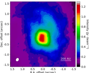
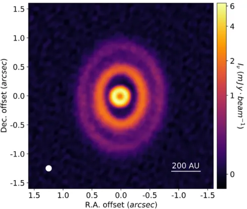
Figure 1. All panels are centered on the stellar position provided by GAIA DR2 (ICRS R.A.=5h29m08 390 and decl.=11°52′12 661). (a) The ALMA
self-calibrated dust continuum map performed with a 0 098 circular beam (bottom left corner; rms noise level σ ∼40 μJy beam−1). A larger view of this panel is provided in AppendixB. (b) The ALMA12CO J=2–1 first-moment map performed with a 0 122×0 159 beam with a position angle of −32°.3 (bottom left corner). The
inset shows a 1″ by 0 5 wide (40 by 20 au) zoom, and the dotted–dashed line highlights the shape of the twist. The averaged uncertainty in the inset region is ∼0.2 km s−1. (c) Simulated ALMA continuum emission map of Model 3, produced in the same way as panel (a). (d) The synthetic first-moment map of the misaligned disk model, applying the model parameters listed in Table2. The color scheme is the same as that in panel (b). (e) The residual map of Model 3. Dashed ellipses mark the fitted location of the three dust rings. The colorbar shows the residual magnitude in units of rms noise level (1σ=∼40 μJy beam−1=∼0.6% of peak surface density). (f) The synthetic first-moment map of the coplanar disk model, with an inclination of 37°.9 and a position angle of −5° throughout the disk. The color scheme is the same as that in panel (b). The data behind panels (a) and (b) are available in the .tar.gz package in two FITS files.
beam. We performed phase self-calibration onto the image with a solution interval of 20 s. This resulted in an rms noise level of ∼40 μJy beam−1 and an enhanced peak signal-to-noise ratio (SNR) of ∼157, compared with ∼63 μJy beam−1 and ∼90 before self-calibration, respectively. The integrated flux density of the disk (195±20 mJy) is consistent with the result from previous ALMA observations (202±20 mJy; Czekala et al.
2017).
The 12CO J=2−1 line data were obtained (after subtracting the continuum on the self-calibrated data) in the
BRIGGS weighting scheme with robust=0.5, and velocity
resolution 0.5 km s−1. The resulting line cube has a beam size of 0 122×0 159 at the position angle −32°.3. The noise level is ∼1.4 mJy beam−1per channel and the peak signal-to-noise ratio is ∼83. Line emission was detected between 7.0 and 20.0 km s−1 with a central velocity of 13.5 km s−1. The integrated flux is 60.6 Jy km s−1, assuming a 2″ radius. The intensity-weighted velocity map (a.k.a., the first-moment map) was constructed by calculating the intensity-weighted velocity with a threshold of three times the noise level. The averaged uncertainty of the twisted pattern in the first-moment map (i.e., the inset in Figure 1(b)) is ∼0.2 km s−1, derived from error propagation theory, assuming the uncertainty of velocity due to the channel resolution is 0.25 km s−1. The observations of the CO isotopologues C18O and13CO J=2−1 emission will be presented in future work.
3. Observational Results
3.1. Dust Continuum Emission
Figure1(a) shows the continuum map with spatial resolution of 0 098 (∼39 au). We identify three dust rings with different apparent shapes in the disk at ∼46, 188, and 338 au (hereafter the inner, middle, and outer ring). The location of the inner ring coincides with the predicted cavity size from SED modeling (Fang et al. 2017). The continuum flux densities of the inner, middle, and outer ring are 42±4, 95±10, and 58±6 mJy, respectively. To our knowledge, the outer ring is the largest ever found in protoplanetary disks.
The three rings harbor an enormous amount of solid material. We estimate the dust (solid) mass Mdustof the rings
with the equation provided in Hildebrand (1983)
k = n n n M F d B T , 1 dust 2 dust ( ) ( )
where Fνis the continuum surface brightness at a submillimeter
frequency ν, d is the distance from the observer to the source,
Bν(Tdust)is the Planck function at the dust temperature Tdust,
and κν is the dust opacity. The dust temperature is estimated
using a fitting function provided by Dong et al. (2018b)
= -T L L r 30 38 100AU , 2 dust 1 4 1 2 ⎜ ⎟ ⎛ ⎝ ⎜ ⎞ ⎠ ⎟ ⎛⎝ ⎞⎠ ( )
where Låis the total stellar luminosity, and r is the location of
the ring. The stellar luminosity modified by the distance provided by GAIA DR2 is 49.3±7.4 Le(Calvet et al.2004;
Gaia Collaboration et al. 2018). We assume a dust grain opacity of 10 cm2g−1at 1000 GHz with a power-law index of 1 (Beckwith et al. 1990). We estimate the dust masses of the rings to be 74±8, 168±19, and 245±28 M⊕, respectively,
with the uncertainties incorporating the uncertainties in the
surface brightness of the rings, source distance, stellar luminosity, and radial location of the rings.
3.2.12COJ=2–1 Emission
Figure1(b) shows the first-moment map of12CO J=2−1 emission (with the zeroth-moment map provided in AppendixA). For regular Keplerian rotating disks, we expect a well-defined butterfly-like pattern in the first-moment map. However, we find a twisted pattern inside ∼0 2, which may result from a misalignment between the inner and outer parts of the disk (i.e., having different inclinations and orientations; Rosenfeld et al.2014), as has been found in the disks around, e.g., HD 142527 (Casassus et al.2015; Marino et al.2015)and HD 143006 (Benisty et al.2018; Pérez et al.2018).
4. Modeling of Dust and Gas Emission
The different apparent shapes of the rings could result from a few scenarios, such as coplanar rings with different eccentri-cities, circular rings with different inclinations, or rings with both different eccentricities and inclinations. Here we present evidence for disk misalignment and disk eccentricity found in modeling the dust and gas emission.
4.1. Visibility Modeling of the Dust Continuum Emission
We fit the dust continuum map assuming that there are three dust rings in the disk with Gaussian radial profiles of surface brightness = s -F ri F e0,i , 3 r r i i 2 2 2 ( ) ( ) ( )
where Fiis the surface brightness as a function of the distance to the center r, with i=1, 2, 3 denoting parameters for the inner, middle, and outer ring, respectively. F0,i is the peak surface
brightness, riis the radius of the ring (i.e., where the ring has the highest surface brightness), and σiis the standard deviation.
Initially, we assume all three rings are intrinsically circular when viewed face-on, and their different apparent shapes entirely originate from different inclinations. For each ring, we assume an independent set of peak surface brightness, center location, radius, width, inclination, and position angle as the model parameters. We call this combination of assumptions Model 1.
After projecting the rings according to their position angles and inclinations, we calculate the synthetic visibility of the models using GALARIO (Tazzari et al. 2018), and launch MCMC parameter surveys to derive posterior distribution of model parameters usingEMCEE(Foreman-Mackey et al.2013). In the MCMC parameter surveys, the likelihood function L is defined as = - å ´ -+ -= L m ReV ReV ImV ImV ln 1 2 , 4 j N j j j j j 1 obs, mod, 2 obs, mod, 2 [( ) ( ) ] ( )
where Vobs is the visibility data from ALMA observations,
Vmodis the synthetic model visibility, N is the total number of
visibility data points in Vobs, and mj is the weight of each visibility data point in Vobs. The prior function is set to
guarantee the surface brightness, ring radius, and ring width do not go below zero, the position angle does not go beyond (−90, 90) degrees, and the inclination does not go beyond (0, 90) degrees. For each model, there are 144 chains spread in
the hyperspace of parameters. Each chain has 15,000 iterations including 10,000 burn-in iterations. The results of the parameter surveys are listed in Table1.
The fitting result of Model 1, listed in Table 1(a), suggests that the three rings have statistically different centers. Particularly, the center of the inner ring differs from the centers of the outer two by ∼20% of the inner ringʼs radius. This nonconcentricity indicates nonzero intrinsic eccentricities in the rings, particularly the inner ring (see Section5.1).
We explore the nonzero intrinsic eccentricity in the inner ring with two models. In both models, the outer two rings are intrinsically circular and concentric. Their center coincides with one of the two foci of the inner ring. In Model 2, that center is set free, while in Model 3 it is assumed to coincide with the stellar position provided by GAIA DR2 (Gaia Collaboration et al. 2018). In those two models, we introduce two more
parameters for the intrinsic eccentricity and apoapsis angle of the inner ring. The position angle only indicates the direction to the ascending node on the axis along which the ring is inclined. The fitting results are listed in Tables 1(b) and (c), and the following calculations are based on the result of Model 3.
Figures1(c) and (e) show the model image and the residual map of Model 3, respectively. The residual map is produced by subtracting model from data in the visibility plane, and then imaging the results in the same way used for the observations. We interpret the residuals as additional substructures on top of the ideal model (e.g., a warp within the ring; Huang et al.
2020).
All three models yield roughly consistent inclinations and position angles of each ring. However, we cannot determine the mutual inclinations between them (i.e., the angles between their angular momentum vectors) from dust emission modeling alone, due to the unknown direction of orbital motion. Table 1
The Complete MCMC Result of Dust Continuum Visibility Modeling (a) Model 1
Inner Ring Middle Ring Outer Ring
R.A Offset [arcsecond] ´
--+ ´´ -1.89 10 2 9.49 10 9.47 10 5 5 - ´ --+ ´´ - -2.44 10 3 2.08 10 1.82 10 4 4 - ´ -- ´ + ´ -4.24 10 3 3.91 10 4.64 10 4 4
decl. Offset [arcsecond] -1.32´10-2-+1.01 101.09 10´´ --4
4 - ´ -- ´ + ´ - -2.26 10 2 2.06 10 2.22 10 4 4 - ´ -- ´ + ´ -1.21 10 2 4.67 10 6.57 10 4 4
Ring Radius [arcsecond] ´ - -+ ´´
-1.15 10 1 1.48 10 1.46 10 4 4 ´ -- ´ + ´ -4.68 10 1 2.92 10 3.07 10 4 4 ´ -- ´ + ´ -8.40 10 1 1.15 10 1.03 10 3 3
Ring Width [arcsecond] ´ - -+ ´´
-4.97 10 2 6.24 10 3.16 10 4 4 ´ --+ ´´ -1.74 10 1 7.56 10 6.69 10 4 4 ´ -- ´ + ´ -3.32 10 1 2.78 10 1.84 10 3 3
Surface Brightness [Jy/pixel] ´
-- ´ + ´ -2.49 10 4 1.56 10 1.80 10 6 6 ´ -- ´ + ´ -3.96 10 5 1.69 10 8.67 10 7 8 ´ -- ´ + ´ -1.13 10 5 5.52 10 2.77 10 7 8 Inclination [degree] 22.24-+0.310.23 32.62-+0.110.07 37.93-+0.080.09
Position Angle [degree] -60.75-+0.561.06 -7.43-+0.120.19 -3.57-+0.120.15
(b) Model 2
Inner Ring Middle Ring Outer Ring
R.A Offset [arcsecond] ´ - -+ ´´
-1.77 10 2 1.61 10 1.69 10 4 4
decl. Offset [arcsecond] -2.22´10-2-+1.99 101.95 10´´ --4
4
Ring Radius [arcsecond] ´ - -+ ´´
-1.17 10 1 1.35 10 1.36 10 4 4 ´ -- ´ + ´ -4.68 10 1 2.71 10 2.88 10 4 4 ´ -- ´ + ´ -8.40 10 1 9.53 10 9.48 10 4 4
Ring Width [arcsecond] ´
-- ´ + ´ -4.97 10 2 3.91 10 3.16 10 4 4 ´ --+ ´´ -1.74 10 1 6.03 10 6.66 10 4 4 ´ -- ´ + ´ -3.30 10 1 1.96 10 1.68 10 3 3
Surface Brightness [Jy/pixel] ´
-- ´ + ´ -2.51 10 4 1.55 10 1.53 10 6 6 ´ -- ´ + ´ -3.96 10 5 1.01 10 8.20 10 7 8 ´ -- ´ + ´ -1.13 10 5 3.37 10 2.65 10 8 8 Inclination [degree] 23.15-+0.230.22 32.64-+0.070.07 37.91-+0.070.08
Position Angle [degree] -55.67-+0.500.61 -7.44-+0.120.14 -3.60-+0.110.13
Apoapsis Angle [degree] 65.04-+0.490.50 L L
Eccentricity 0.21-+1.43 101.75 10´´ --3 3
L L
(c) Model 3
Inner Ring Middle Ring Outer Ring
Ring Radius [arcsecond] ´ - -+ ´´
-1.16 10 1 1.49 10 1.20 10 4 4 ´ -- ´ + ´ -4.68 10 1 2.98 10 2.72 10 4 4 ´ -- ´ + ´ -8.37 10 1 1.06 10 8.95 10 3 4
Ring Width [arcsecond] ´
-- ´ + ´ -4.99 10 2 3.86 10 3.06 10 4 4 ´ --+ ´´ -1.73 10 1 5.98 10 6.33 10 4 4 ´ -- ´ + ´ -3.39 10 1 1.85 10 1.90 10 3 3
Surface Brightness [Jy/pixel] ´
-- ´ + ´ -2.47 10 4 1.42 10 1.64 10 6 6 ´ -- ´ + ´ -3.94 10 5 1.12 10 8.55 10 7 8 ´ -- ´ + ´ -1.13 10 5 3.33 10 2.63 10 8 8 Inclination [degree] 20.63-+0.290.23 32.86-+0.070.06 37.96-+0.080.09
Position Angle [degree] -60.37-+0.650.81 -7.26+-0.130.13 -3.49-+0.120.13
Apoapsis Angle [degree] 121.39-+0.250.26 L L
Eccentricity 0.19-+6.46 108.55 10´´ --4 4
L L
Note.The radius of each ring is the location of the peak in our model in Section4, and the width is the full width at half maximum (FWHM) of the profile. The center offsets for Model 1 and Model 2 are relative to the center in Model 3, which is the location of GW Ori provided by GAIA DR2 (ICRS R.A.=5h29m08 390 and decl.=11°52′12 661). The position angles and apoapsis angles are measured east of north. The inclination is defined in the range from 0° to 90°, with 0° denoting face-on. The pixel size in the unit of surface brightness is determined internally byGALARIO.
4.2. Kinematics Modeling of the12COJ=2−1 Emission
Following the prescription and parameter values used to fit low resolution CO isotopologue data of GW Ori (Fang et al.
2017), we set up a gas surface density model using a power-law profile with an exponential tail
S = S -g - - -g r r r e , 5 c c r rc2 ⎛ ⎝ ⎜ ⎞ ⎠ ⎟ ( ) [ ( ) ] ( )
and the aspect ratio h/r parameterized as
= y h r h r r r , 6 c c ⎜ ⎟ ⎛ ⎝ ⎞ ⎠ ⎛ ⎝ ⎜ ⎞ ⎠ ⎟ ( )
where Σc and (h/r)c are corresponding values at the characteristic scaling radius rc. The disk mass is taken as 0.12 Me, corresponding to Σc=3 g cm
−2
for rc=320 au, with γ=1.0, (h/r)c=0.18, and ψ=0.1. The dust surface density profile is set by assuming a gas-to-dust ratio of 100, and decreasing the dust surface density by a factor of 1000 inside the derived gap radii: inside 37 au, from 56 to 153 au, and from 221 to 269 au. The12CO channel maps are then computed and ray-traced by the physical-chemical modeling code DALI
(Bruderer 2013), which simultaneously solves the heating-cooling balance of the gas and chemistry to determine the gas temperature, molecular abundances, and molecular excitation for a given density structure.
Similar to Walsh et al. (2017), we model the misaligned disk with an inner cavity and three annuli each with its own inclination and position angle,19 as listed in Table 2. The channel map is run through the ALMA simulator using the settings of the ALMA observations. The resulting first-moment map is shown in Figure 1(d). In Figure 1(f) we show the simulated first-moment map for another model as a compar-ison, in which the disk is coplanar with an inclination of 37°.9 and a position angle of −5°.
The models show that the 12CO J=2−1 first-moment map in the ALMA observation cannot be reproduced by a
coplanar disk. Instead, the misaligned disk model described in Table 2 matches the observed first-moment map better, indicating the presence of misalignment in the GW Ori disk.
5. Discussions
Several disks have been observed to have nonzero eccentricity and/or misalignment (e.g., MWC 758, Dong et al. 2018a; HD 142527, Casassus et al. 2015; Marino et al.
2015; and HD 143006, Benisty et al.2018; Pérez et al.2018). Unlike most of them, in which the origin is uncertain, the GW Ori system provides a strong and direct link between substructures and star–disk gravitational interactions. There-fore, it offers a unique laboratory to probe three-dimensional star–disk interactions. In this section, we discuss the possible origins of the observed substructures due to star–disk interactions.
5.1. Disk Eccentricity
The A–B binary and the C component can be dynamically viewed as an AB–C binary. The eccentricity of the circumbin-ary disk may increase through resonant interactions with the binary (Papaloizou et al.2001). In the case of no binary-disk misalignment, the binaryʼs perturbing gravitational potential on the midplane of the disk is given by Lubow (1991). The coupling of this perturbing potential with the imposed eccentricity of the disk excites density waves at the 1:3 outer eccentric Lindblad resonance, which lead to angular momen-tum removal in the inner parts of the disk. As no energy is removed along with the angular momentum in this process, the disk orbit cannot remain circular (Papaloizou et al. 2001). In the case of GW Ori, the inner dust ring is the most susceptible to this effect, which could explain why its center in Model 1 is more deviated from those of the other two rings.
5.2. Binary-disk Misalignment
Our dust and gas observations alone cannot break the degeneracy in the mutual inclination between different parts in the disk due to the unknown on-sky projected orbital direction of the disk. Previous studies indicate that the on-sky projected gas motion is likely to be clockwise (Czekala et al.2017), same as the orbital motion of GW Ori C given by astrometric observations (Berger et al. 2011). Given the inclination and longitude of ascending node of the AB-C binary orbit being 150±7 and 282±9 degrees (Czekala et al.2017), we assume that the entire disk has the same clockwise on-sky projected orbital direction. Following Fekel (1981), we find out that the binary-disk misalignments at 46 au (the inner ring), 100 au (a gap), 188 au (the middle ring), and 338 au (outer ring) are 11±6, ∼28,20 35±5, and 40±5 degrees, respectively. A schematic diagram of our disk model is displayed in Figure2. Therefore, the inner ring and the AB-C binary plane are close to being coplanar, and there is a monotonic trend of binary-disk misalignment from ∼10° at ∼50 au to ∼40° at ∼340 au, consistent with the expected outcome of the disk misalignment (see Section5.3).
Several mechanisms could produce an initial binary-disk misalignment, such as turbulence in the star-forming gas clouds (Bate2012), binary formation in the gas cloud whose physical Table 2
The Parameters Used in the Gas Kinematics Modeling
Inner Ring Outer Ring Longitude of the Inclination Ascending Node
(au) (au) (degree) (degree)
0 32 No Emission
32 48 −60 22.3
48 153 −10 17.3
153 1000 −5 37.9
Note.The annuli are concentric with the center located at the stellar position provided by GAIA DR2 (ICRS R.A.=5h29m08 390 and decl.=11°52′ 12 661). The longitude of the ascending node is measured east of north, and the inclination is defined in the range from 0° to 90° with 0° meaning face-on. The disk model is composed of an empty inner cavity and three annuli, inside out. The inner annulus (from 32 to 48 au) is for the inner dust ring. The outer annulus (from 153 to 1000 au) is for the middle and outer dust rings. The middle annulus (from 48 to 153 au) is for the gap in between.
19
DALIis unable to vary inclination as a function of radius. The final channel map is constructed by concatenating three channel maps, each for one component, ray-traced at its inclination and position angle and cut out at the specified radius range listed in Table2.
20
The manual fitting of the gas model cannot provide any uncertainties for the gap between the inner and middle rings.
axes are misaligned to the rotation axis (Bonnell & Bastien 1992), and accretion of cloud materials with mis-aligned angular momentum with respect to the binary after the binary formation (Bate2018).
5.3. Misalignment within the Disk
A test particle orbiting a binary on a misaligned orbit undergoes nodal precession due to gravitational perturbations from the binary (Nixon et al.2011; Facchini et al.2018). For a protoplanetary disk in the bending-wave regime (i.e., where the aspect ratio is higher than the α-prescription of viscosity; Shakura & Sunyaev 1973), disk parts at different radii shall undergo global precession like a rigid body with possibly a small warp (Smallwood et al.2019). Therefore, the timescale of radial communication of disk materials (i.e., for pressure-induced bending waves propagating at half of the sound speed) and the timescale of global precession determine whether the disk can develop a misalignment inside.
Assuming an inner radius at 32 au (3–4 times the AB-C binary semimajor axis; Czekala et al.2017; Kraus et al.2020) and an outer radius at 1300 au (size of the gas disk; Fang et al.
2017), the global precession timescale of the entire disk is ∼0.83 Myr, and the radial communication timescale is ∼0.06 Myr (see Appendix D.1 and D.2 for detailed calcula-tions). The radial communication is able to prevent the disk from breaking or developing a significant warp, and we would not expect the observed large deviations in the inclination and position angle between the inner and middle ring. Therefore, we propose that the gap between the inner and middle ring is
deep enough to break the disk into two parts (hereafter the inner and outer disk), undergoing nodal precession indepen-dently, due to another mechanism.
Due to the viscous dissipation, the precessing disk is torqued toward either polar alignment (i.e., the binary-disk misalign-ment becomes 90°; Martin & Lubow 2017; Zanazzi & Lai 2018), or coplanar alignment/counteralignment. The minimum critical initial binary-disk misalignment for which a disk moves toward polar alignment is ∼63° in the limit of zero disk mass. Since a higher disk mass will lead to a larger critical angle (Martin & Lubow2019), the GW Ori disk is most likely moving toward coplanar alignment. As we propose that the disk breaks into two parts undergoing global precession independently, they are also aligning to the binary indepen-dently on different timescales.
Assuming the radial communication is blocked at 60 au, we estimate the alignment timescales to be ∼1 Myr for the inner disk and above 100 Myr for the outer disk (see AppendixD.3). This is consistent with the observed significantly smaller inclination of the inner ring with respect to the binary than those of the outer rings. The latter are likely inherited from birth and have not evolved much given the system age.
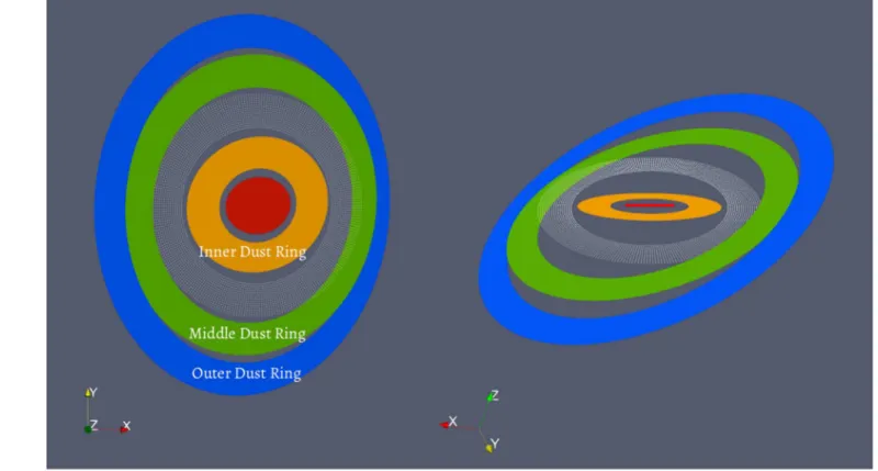
If the radial communication is also blocked at the gap between the middle and outer rings (e.g., ∼250 au), the nodal precession timescales for the middle and outer rings would be ∼0.6 Myr and ∼120 Myr, respectively, and the two rings are likely to develop significantly different position angles. Thus we propose that the gap between the middle and outer rings does not cut off the radial communication, and the two rings Figure 2. Schematic diagram showing the proposed geometry of the system. Orbital planes of the AB-C binary (red), the inner dust ring (orange), the gap between the inner and middle dust rings (white dots), the middle dust ring (green), and the outer dust ring (blue) are marked inside out. The left panel is a sky-projected view, and in the right panel the binary is edge-on. The size of the disk components are not to-scale. The orientation axes are shown at the bottom left corner of each panel, with the x-axis being antiparallel to the R.A. direction, the y-axis being parallel to the decl. direction, and the z-axis pointing at the observer.
precess roughly as a rigid body with only a small warp between them.
5.4. Hydrodynamic Simulations
The analytical results suggest that the radial communication is able to prevent the binary from breaking the disk (e.g., Nixon et al.2013). As a result, we propose a break at ∼60 au that is due to other mechanisms in order to explain the observed structures. We carry out a demonstrative smoothed particle hydrodynamic (SPH) simulation with the PHANTOM code (Lodato & Price 2010; Price & Federrath 2010; Price et al.
2018) to test the nonbreaking hypothesis in the nonlinear regime. The results are shown in Figure3.
We model the triple-star system as the outer binary in order to speed up the simulation. The simulation consists of 106equal mass Lagrangian SPH particles initially distributed from
rin=40 au to rout=400 au. The initial truncation radius of
the disk does not affect the simulation significantly, since the material moves inwards quickly due to the short local viscous timescale. A smaller initial outer truncation radius rout than
what is observed is chosen in order to better resolve the disk. The binary begins at apastron with eb=0.22 and ab=9.2 au
(Czekala et al. 2017). The accretion radius of each binary component is 4 au. Particles within this radius are accreted, and their mass and angular momentum are added to the star. We ignore the effect of self-gravity since it has no effect on the nodal precession rate of flat circumbinary disks.
The initial surface density profile is taken by
Sr = S r r - , 7
0 0 3 2
( ) ( ) ( )
where Σ0is the density normalization at r0=40 au,
corresp-onding to a total disk mass of 0.1 Me. We take a locally
isothermal disk with a constant aspect ratio h/r=0.05, where
h is the scale height. The Shakura & Sunyaev (1973)α parameter varies in the range 0.008–0.013 over the disk. The SPH artificial viscosity αAV=0.31 mimics a disk with
a» a á ñH
h
10 8
AV ( )
(Lodato & Price 2010), where á ñH is the mean smoothing length on particles in a cylindrical ring at a given radius and we take βAV=2. The disk is resolved with average smoothing
length per scale height of 0.32.
The evolution of surface density, binary-disk misalignment, and longitude of the ascending node at different radii suggest that the disk does not show any sign of breaking in 3000 binaryʼs orbital periods (∼0.04 Myr), which is sufficiently long to tell if the disk would break or not since the radial communication timescale in the simulation is ∼0.01 Myr. Instead, the disk presents a global warp. The warp is not taken into account in the analytic estimates. The small outer truncation radius in the simulation leads to a faster precession timescale than that predicted by the analytic model, comparable to the radial communication timescale. The simulations suggests that unless the disk is very cool (i.e., low aspect ratio) and in the viscous regime, some other mechanism, e.g., a companion, is needed to break the disk at the gap between the inner and middle rings. This mechanism may also be responsible for producing the observed misalignment in the disk.
A disk with a lower aspect ratio or a higher α value, such that it falls into the viscous regime (h/r<α), may break due to the binaryʼs torque (Nixon et al.2013). However, observations have suggested lower α values than our adaption here (e.g., α10−3
, Flaherty et al. 2017). A lower viscosity leads to a larger binary truncation radius (Artymowicz & Lubow1994), and a longer global precession timescale (Equation (D4)). Therefore we expect even less warping (and no break) in the GW Ori disk than in our simulation.
Figure 3. Result of the SPH simulation. Upper panel:radial profile of the surface density of the disk. M and a are the total mass and separation of the AB-C binary in code units, respectively. Middle panel:radial profile of the binary-disk misalignment. Lower panel:radial profile of the longitude of the ascending node of the disk, measured from the binaryʼs orbital plane.
6. Conclusions
We present the ALMA 1.3 mm dust continuum observation and 12CO J=2−1 emission of the circumtriple disk around GW Ori. Our main conclusions are the following:
1. For the first time, we identify three dust rings in the GW Ori disk at ∼46, 188, and 338 au, with their estimated dust mass being ∼74, 168, and 245 M⊕, respectively. The
three dust rings have enough solids to make many cores of giant planets (∼10 M⊕; Pollack et al. 1996).
2. We built three models under various assumptions to fit the dust continuum observations using MCMC fitting. Our results (Table 1) suggest that the inner ring has an eccentricity of ∼0.2, and the three rings have statistically different on-sky projected inclinations. The inner, middle, and outer rings are likely misaligned by ∼11, 35, and 40 degrees to the orbital plane of the GW Ori AB-C binary system, respectively.
3. A twisted pattern is identified in the first-moment map, suggesting the presence of a warp in the disk, consistent with what we have found in the dust continuum emission. 4. Using analytical analysis and hydrodynamic simulations, we find that the torque from the GW Ori triple stars alone cannot explain the observed large misalignment between the inner and middle dust rings. The disk would not break due to the torque, and a continuous disk is unlikely to show the observed large misalignment. Therefore, this hints at some other mechanism that breaks the disk and prevents radial communication of bending waves between the inner and middle rings.
There are still open questions associated with the system. For example, are there any companions in the disk? Dust rings and gaps have been shown to be common in protoplanetary disks (Andrews et al.2018; Huang et al.2018; Long et al.2018; van der Marel et al.2019), and one of the most exciting hypotheses is that they are produced by embedded companions ranging from stellar-mass all the way to super-Earths (Artymowicz & Lubow 1994; Dong et al. 2015; Zhang et al. 2018). Specifically, a companion may be opening the gap between the inner and middle rings and breaking the disk there. Companions at hundreds of astronomical units from their host stars have been found before (e.g., HD 106906 b; Bailey et al.
2014). But how they form, i.e., forming in situ or at closer distances, or followed by scattering or migration to the outer regions, is unclear. If GW Oriʼs dust rings are in the process of forming companions, there will be circumtriple companions, which have not been found before (excluding quadruple systems; Busetti et al. 2018). The system will offer direct clues on the formation of distant companions.
We thank Sean Andrews, Myriam Benisty, John Carpenter, Ian Czekala, Sheng-Yuan Liu, Feng Long, Diego Muñoz, Rebecca Nealon, Henry Ngo, Laura Pérez, John Zanazzi, and Zhaohuan Zhu for discussions. We also thank the anonymous referee for constructive suggestions that largely improved the quality of the paper. J.B. thanks Belaid Moa for help on the numerical implementation. This paper makes use of the
following ALMA data: ADS/JAO.ALMA#2017.1.00286.S. ALMA is a partnership of ESO (representing its member states), NSF (USA) and NINS (Japan), together with NRC (Canada), MOST and ASIAA (Taiwan), and KASI (Republic of Korea), in cooperation with the Republic of Chile. The Joint ALMA Observatory is operated by ESO, auI/NRAO, and NAOJ. The National Radio Astronomy Observatory is a facility of the National Science Foundation operated under cooperative agreement by Associated Universities, Inc. Num-erical calculations are performed on the clusters provided by ComputeCanada. This work is in part supported by JSPS KAKENHI grant Nos. 19K03932, 18H05441, and 17H01103 and NAOJ ALMA Scientific Research grant No. 2016-02A. Financial support is provided by the Natural Sciences and Engineering Research Council of Canada through a Discovery Grant awarded to R.D. N.v.d.M. acknowledges support from the Banting Postdoctoral Fellowships program, administered by the Government of Canada. R.G.M. acknowledges support from NASA through grant NNX17AB96G. H.B.L. is sup-ported by the Ministry of Science and Technology (MoST) of Taiwan (grant Nos. 108-2112-M-001-002-MY3). Y.H. is supported by the Jet Propulsion Laboratory, California Institute of Technology, under a contract with the National Aeronautics and Space Administration. K.T is supported by JSPS KAKENHI 16H05998 and 18H05440, and NAOJ ALMA Scientific Research Grant 2017-05A.
Appendix A
ALMA12CO J=2−1 Zeroth-moment Map FigureA1 shows the ALMA zeroth-moment map of 12CO
J=2−1 emission. The spiral-like structure at ∼0 75 to the
northwest is likely due to cloud contamination, as reported by previous studies (Czekala et al.2017; Fang et al.2017).
Appendix B
A Larger View of Figure1(a) FigureB1shows a larger view of Figure1(a).
Appendix C
The UV-plot and Posterior Distribution of Dust Modeling Figure C1 shows the uv-plot and posterior distribution of Model 3.
Appendix D
Equations for the Timescale Analysis
D.1. Radial Communication Timescale
For a disk around a binary system of separation ab, its radial communication timescale tc can be estimated by Lubow & Martin (2018) » W t h r r a 8 5 , D1 c b out out b 3 2 ⎛ ⎝ ⎜ ⎞ ⎠ ⎟ ( ) ( )
where routis the outer radius within which the disk is in good
radial communication, and (h/r)out is the aspect ratio at rout,
calculated based on the estimated temperature in the disk (Equation (2)). The radial communication timescale of the entire disk (i.e., rout=1300 au) is estimated to be ∼0.06 Myr.
D.2. Nodal Precession Timescale
If there is no radial communication in the disk, each part of the disk shall undergo differential precession with its local precession angular frequency ωn,localgiven by Smallwood et al. (2019)
w =k a W r , D2 n,local b 7 2 b ⎜ ⎟ ⎛ ⎝ ⎞ ⎠ ( ) where = + -+ k e e M M M M 3 4 1 3 b 4 D3 2 b4 1 2 1 2 2 ( ) ( )
is a constant depending on the eccentricity of binaryʼs orbit eb,
and the primary and secondary mass of the binary M1and M2.
However, for a protoplanetary disk in the bending-wave regime, where radial communication is active and prompt, the disk parts Figure C1. Quality of MCMC parameter search for Model 3. The uv-visibility panel shows the uv-plot of both the ALMA observation and its best-fit model, with the upper panel for the real part of visibility and the lower panel for the imaginary part. The surrounding panels show the histograms of chains in the MCMC fitting. The best-fit value is taken from the fiftieth percentile of the distribution (vertical red line), and the negative and positive uncertainties are taken from sixteenth and eighty-fourth percentile, respectively. The seven columns are for the peak surface brightness, apoapsis angle (inner ring only), eccentricity (inner ring only), inclination, position angle, radius, and width, from left to right. The three rows (top-down) are for the inner, middle, and outer rings. The units of parameters in the histograms are the same as those in Table1(c).
at different radii shall undergo global precession with the angular frequency ωn,globalgiven by Smallwood et al. (2019)
w =k a W r , D4 n,global b 7 2 b ⎜ ⎟ ⎛ ⎝ ⎞ ⎠ ( ) and
ò
ò
= S W S W a r r a r r r r d d D5 r r r r b 7 2 3 b 7 2 3 in out in out ⎜ ⎟ ⎛ ⎝ ⎞ ⎠ ( ) ( )is the angular momentum weighted averaging term, in whichΩ (r)is the angular frequency at a given radius r,Σ(r) is the disk surface density with a radial dependence of r−3/2, and rinand
routare inner and outer radii of the disk. Assuming rin=32 au
and rout=1300 au, we take tn,global=2π/ωn,global and
esti-mate the global precession timescale of the entire GW Ori disk to be ∼0.83 Myr.
D.3. Alignment Timescale
The alignment timescale ta is given by Lubow & Martin
(2018)and Bate et al. (2000)
a w = W ta h r , D6 2 b n 2 ( ) ( )
where α=0.01, h/r is defined in Equation (6), and the angular frequency of global precession (Equation (D4))is used for ωn.
ORCID iDs
Jiaqing Bi https://orcid.org/0000-0002-0605-4961
Nienke van der Marel https://orcid.org/0000-0003-2458-9756
Ruobing Dong (董若冰) https://orcid.org/0000-0001-9290-7846
Rebecca G. Martin https://orcid.org/0000-0003-2401-7168
Jun Hashimoto https://orcid.org/0000-0002-3053-3575
Hideko Nomura https://orcid.org/0000-0002-7058-7682
Michihiro Takami https://orcid.org/0000-0001-9248-7546
Mihoko Konishi https://orcid.org/0000-0003-0114-0542
Munetake Momose https://orcid.org/0000-0002-3001-0897
Kazuhiro D. Kanagawa https://orcid.org/0000-0001-7235-2417
Akimasa Kataoka https://orcid.org/0000-0003-4562-4119
Tomohiro Ono https://orcid.org/0000-0001-8524-6939
Michael L. Sitko https://orcid.org/0000-0003-1799-1755
Sanemichi Z. Takahashi https://orcid.org/0000-0003-3038-364X
Kengo Tomida https://orcid.org/0000-0001-8105-8113
Takashi Tsukagoshi https://orcid.org/0000-0002-6034-2892
References
Andrews, S. M., Huang, J., Pérez, L. M., et al. 2018,ApJL,869, L41
Artymowicz, P., & Lubow, S. H. 1994,ApJ,421, 651
Bailey, V., Meshkat, T., Reiter, M., et al. 2014,ApJL,780, L4
Bate, M. R. 2012,MNRAS,419, 3115
Bate, M. R. 2018,MNRAS,475, 5618
Bate, M. R., Bonnell, I. A., Clarke, C. J., et al. 2000,MNRAS,317, 773
Beckwith, S. V. W., Sargent, A. I., Chini, R. S., & Guesten, R. 1990,AJ,
99, 924
Benisty, M., Juhász, A., Facchini, S., et al. 2018,A&A,619, A171
Berger, J. P., Monnier, J. D., Millan-Gabet, R., et al. 2011,A&A,529, L1
Bonnell, I., & Bastien, P. 1992,ApJ,401, 654
Bruderer, S. 2013,A&A,559, A46
Busetti, F., Beust, H., & Harley, C. 2018,A&A,619, A91
Calvet, N., Muzerolle, J., Briceño, C., et al. 2004,AJ,128, 1294
Casassus, S., Marino, S., Pérez, S., et al. 2015,ApJ,811, 92
Czekala, I., Andrews, S. M., Torres, G., et al. 2017,ApJ,851, 132
Dong, R., Liu, S.-y., Eisner, J., et al. 2018a,ApJ,860, 124
Dong, R., Najita, J. R., & Brittain, S. 2018b,ApJ,862, 103
Dong, R., Zhu, Z., & Whitney, B. 2015,ApJ,809, 93
Facchini, S., Juhász, A., & Lodato, G. 2018,MNRAS,473, 4459
Fang, M., Sicilia-Aguilar, A., Roccatagliata, V., et al. 2014,A&A,570, A118
Fang, M., Sicilia-Aguilar, A., Wilner, D., et al. 2017,A&A,603, A132
Fekel, F. C. J. 1981,ApJ,246, 879
Flaherty, K. M., Hughes, A. M., Rose, S., et al. 2017, AAS Meeting,229, 327.07
Foreman-Mackey, D., Hogg, D. W., Lang, D., & Goodman, J. 2013,PASP,
125, 306
Gaia Collaboration, Brown, A. G. A., Vallenari, A., et al. 2018,A&A,616, A1
Hildebrand, R. H. 1983, QJRAS,24, 267
Huang, J., Andrews, S. M., Dullemond, C. P., et al. 2018,ApJL,869, L42
Huang, J., Andrews, S. M., Dullemond, C. P., et al. 2020,ApJ,891, 48
Kraus, S., Kreplin, A., Young, A. K., et al. 2020, arXiv:2004.01204
Lodato, G., & Price, D. J. 2010,MNRAS,405, 1212
Long, F., Pinilla, P., Herczeg, G. J., et al. 2018,ApJ,869, 17
Lubow, S. H. 1991,ApJ,381, 259
Lubow, S. H., & Martin, R. G. 2018,MNRAS,473, 3733
Marino, S., Perez, S., & Casassus, S. 2015,ApJL,798, L44
Martin, R. G., & Lubow, S. H. 2017,ApJL,835, L28
Martin, R. G., & Lubow, S. H. 2019,MNRAS,490, 1332
Mathieu, R. D., Adams, F. C., & Latham, D. W. 1991,AJ,101, 2184
McMullin, J. P., Waters, B., Schiebel, D., Young, W., & Golap, K. 2007, in ASP Conf. Ser. 376, CASA Architecture and Applications, ed. R. A. Shaw, F. Hill, & D. J. Bell (San Francisco, CA: ASP),127
Nixon, C., King, A., & Price, D. 2013,MNRAS,434, 1946
Nixon, C. J., King, A. R., & Pringle, J. E. 2011,MNRAS,417, L66
Papaloizou, J. C. B., Nelson, R. P., & Masset, F. 2001,A&A,366, 263
Pérez, L. M., Benisty, M., Andrews, S. M., et al. 2018,ApJL,869, L50
Pollack, J. B., Hubickyj, O., Bodenheimer, P., et al. 1996,Icar,124, 62
Price, D. J., & Federrath, C. 2010,MNRAS,406, 1659
Price, D. J., Wurster, J., Tricco, T. S., et al. 2018,PASA,35, e031
Rosenfeld, K. A., Chiang, E., & Andrews, S. M. 2014,ApJ,782, 62
Shakura, N. I., & Sunyaev, R. A. 1973, A&A,500, 33
Smallwood, J. L., Lubow, S. H., Franchini, A., & Martin, R. G. 2019,
MNRAS,486, 2919
Tazzari, M., Beaujean, F., & Testi, L. 2018,MNRAS,476, 4527
van der Marel, N., Dong, R., di Francesco, J., Williams, J. P., & Tobin, J. 2019,
ApJ,872, 112
Walsh, C., Daley, C., Facchini, S., & Juhász, A. 2017,A&A,607, A114
Zanazzi, J. J., & Lai, D. 2018,MNRAS,473, 603