See discussions, stats, and author profiles for this publication at: https://www.researchgate.net/publication/224202502
A new approach for wireless communication
systems based on IDMA technique
Conference Paper · November 2010 DOI: 10.1109/ISVC.2010.5656727 · Source: IEEE Xplore CITATIONS2
READS39
4 authors, including: Some of the authors of this publication are also working on these related projects: Information retrievalView project
Channel modellingView project
Awatif Rouijel Mohammed V University of Rabat 9 PUBLICATIONS 9 CITATIONS SEE PROFILE Benayad Nsiri Faculté des Sciences Ain Chock - Casablanca 57 PUBLICATIONS 94 CITATIONS SEE PROFILE Driss Aboutajdine Mohammed V University of Rabat 530 PUBLICATIONS 2,090 CITATIONS SEE PROFILE All content following this page was uploaded by Awatif Rouijel on 05 July 2015. The user has requested enhancement of the downloaded file.978-1-4244-5997-1/10/$26.00 c 2010 IEEE
A New Approach for Wireless Communication
Systems Based on IDMA Technique
Awatif Rouijel
GSCM-LRIT laboratory associated with CNRST Faculty of Science University Mohammed V Agdal Rabat Email: [email protected]Benayad Nsiri
LIAD laboratory Faculty of Sciences University Hassan II ,Ain Chock MOROCCO Email: [email protected]Ahmed Faqihi
and Driss Aboutajdine
GSCM-LRIT laboratory associated with CNRST
Faculty of Science University Mohammed V
Agdal Rabat
Abstract—This paper will propose a novel multiple access tech-nology, called OWDM-IDMA (Orthogonal Wavelength-Division Multiplexing-Interleave Division Multiple Access), which is the combination of OWDM (Orthogonal Wavelength-Division Multi-plexing) and multiple access schemes IDMA (Interleave Division Multiple Access), in which interleaves are used as the only means for user separation. The IDMA receiver principles for different modulation and OWDM principles are outlined. Simulation example of OWDM-IDMA system is provided to demonstrate the advantages of the OWDM-IDMA scheme in terms of bandwidth by estimating the bit error rate (BER) of system, putting themselves in a real communication.
Index Terms—IDMA, OWDM, CWT, DWT, ESE, DWPT, IDWPT.
I. INTRODUCTION
ince the 1980s, the communications sector known as the telecommunications is growing dramatically thanks to tech-nological advances in several scientific fields. This progress is particularly striking for mobile radio communications with the appearance of different generations of mobile telephony. At the Same time, applications that can benefit from this technology have continued to diversify. OWDM (Orthogonal Wavelength-Division Multiplexing) is considered to be promising. IDMA(Interleave-Division Multiple-Access)[1][2]is a special case of random waveform CDMA that is mainly limited by MAI(Multiple Access Interference) and ISI(Inter Symbol Interference); Indeed with IDMA, different users are ,solely, distinguished by user-specific interleaves. These interleavers can be selected randomly and orthogonality is not essential. Turbotype iterative MUD (Multi-User Detection) has been extensively studied to mitigate MAI and ISI, and significant progress has been made.
In this contribution, we propose a new multiple access tech-nique, called OWDM-IDMA which is the combination of OWDM and IDMA techniques, this technique can alleviate ISI by the OWDM technique and cancel multiple access interference (MAI) by the IDMA technique. Indeed, through the formalism of wavelets and their application to wavelet packets and filter banks, it is possible to construct orthogonal basis in time and frequency whose properties will develop a
Multicarrier communication system which uses more accu-rately the radio-electric spectrum.
The system performance is analyzed. A signal-to-noise (SNR) evolution technique is applied to predict the bit-error-rate (BER) performance.
The rest of the paper is organized as follows. In Section 2, we present the transceiver architecture of IDMA. In Section 3, the basics of OWDM are discussed. Afterwards, we present and investigate the performance of our proposed OWDM-IDMA scheme. Finally, we conclude our discourse in Section 6.
II. OVERALL TRANSMITTER AND RECEIVER PRINCIPLE OF IDMA
The technique of multiple access IDMA can allocate the same frequency band to several users while allowing them to transmit simultaneously. IDMA can be regarded as a special case of CDMA where the spreading is done by an arbitrary equal low rate channel code for all users and the separation is done by user-specific interleaves.
A. Transmitter structure
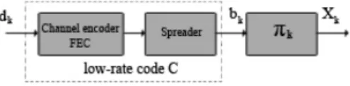
Figure.1 shows the transmitter structure of the multiple access scheme under consideration with K simultaneous users. The input data sequence dk of user k is encoded basically
Fig. 1. Transmitter structure for IDMA system
on a low-rate code C, generating a coded sequence bk = bk(j); j = 1...J where J is the frame length (Here, ”chip” is used instead of ”bit” as the FEC encoding may include spreading or repetition coding.). Then bk is permutated by an interleaver πk, producing Xk = Xk(j). The interleavers πk, are different for different users. We assume that the interleavers are generated independently and randomly. The key principle of IDMA is that the users are solely distinguished
by their interleavers [3]. After chip matched filtering, the received signal from K users can be written as:
r(j) = K X
k=1
hk(j) ∗ Xk(j) + n(j) j = 1, 2, ..., J (1) Where n (j) are the samples of a complex AWGN process with variance σ2 in each dimension, and hk is the channel coefficient for user-k. The channel coefficients hk are assumed known a priori at the receiver side.
B. Receiver Structure
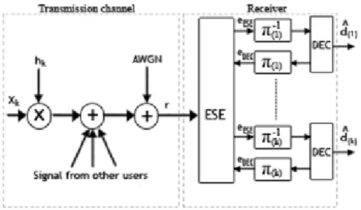
Fig. 2. Receiver structure for IDMA system
The receiver in figure.2 consists of an elementary signal estimator (ESE) and K single-user a posteriori probability (APP) decoders (DECs). The multiple access and coding constraints are considered separately in the ESE and DECs. In the iterative detection process, the ESE and DECs exchange extrinsic information in a turbo-type manner [4][5]. The ESE operation can be carried out in a chip-by-chip manner [6]. C. Chip-by-Chip Detection Algorithm
The chip by chip detection algorithm can be summarized as follows: Initialization: eDEC(xk(j)) = 0 ∀k, j (2) Iterative process: µk(j) = tanheDEC(xk(j)) 2 ∀k, j (3) ϑk(j) = 1 − (µk(j))2 ∀k, j (4) E(r(j)) = K X k=1 hkµk(j) ∀j (5) V ar(r(j)) = σn2+ K X k=1 (hk)2ϑk(j) ∀j (6) E(ξk(j)) = E(r(j)) − hkµk(j) ∀k, j (7) V ar(ξk(j)) = V ar(r(j)) − (hk)2ϑk(j) ∀k, j (8) eESE(xk(j)) = 2hk×r(j) − E(ξk(j)) V ar(ξk(j)) ∀k, j (9) After this last operation, the necessary data information to decode eESE(xk(j)) is obtained. The decoder then calculates the extrinsic log-likelihood ratios (LLR). Once eDEC(xk(j)) decoding is completed, the alculations of equation 3 in equa-tion 9 are repeated.
III. OVERALL PRINCIPLE OF ORTHOGONAL WAVELET DIVISION MULTIPLEX (OWDM) The wavelet transform a time function maps into a two dimension function of a (instead of ω - frequency)and τ , where a is called the scale and τ is the translation of the wavelet function along the time axis[7].
A. The Continuous Wavelet Transform
The Continuous Wavelet Transform (CWT) is provided by equation 10,where S(t) is the signal to be analyzed. t is the time. ψ(t) is the mother wavelet or the basis function. And √1
a(ψ( t−τ
a )) is the baby wavelet [8] made by either stretching or compressing the mother wavelet.All the used wavelet functions in the transformation are derived from the mother wavelet through translation (shifting) and scaling (dilation or compression). CW T (a, τ ) = √1 a Z S(t).ψ(t − τ a )dt (10)
The translation parameter τ relates to the location of the wavelet function as it is shifted through the signal. Thus, it corresponds to the time information in the Wavelet Transform. The scale parameter a is defined as |1/f requency| and corresponds to frequency information. Scaling either dilates (expands) or compresses a signal.
B. The Discrete Wavelet Transform
The Discrete Wavelet Transform (DWT), which is based on sub-band coding, is found to yield a fast calculation of Wavelet Transform. It is easy to implement and reduce the computation time and the required resources. In the case of DWT, a time-scale representation of the digital signal is obtained by using digital filtering techniques.
The DWT is calculated by successive low pass and high pass filtering of the discrete time-domain signal as shown in figure.3.
In the figure 3, the signal is denoted by the sequence x[n],
Fig. 3. Three-level wavelet decomposition tree
while the high pass filter is denoted by H0. The ↓ 2 in the figure is the down-sampling function achieved by discarding alternate samples. The maximum number of levels depends on the length of the signal.
Figure 4 shows the reconstruction of the original signal from the wavelet coefficients. Basically, the reconstruction is the reverse process of decomposition. G0 and H0, are exchanged with the synthesis filters G1 and H1, and the ↑ 2 is the zero insertion function (up-sampling).
After reviewing the whole wavelets theory, it is possible to
Fig. 4. Three-level wavelet reconstruction tree
define a wavelet functions for Multicarrier modulation. So we can define the principle of Multicarrier modulation using wavelet packets.
The basic principles of Multicarrier modulation using wavelet packets are illustrated in figure.5. At the transmitter side, symbols are transformed from the wavelets domain to time domain by an IDWPT (Inverse Discrete Wavelet Packet Transform); At the reception, the received signal is transformed to time domain by a wavelet DWPT (Discrete Wavelet Packet Transform) [8].
In figure.5, the blocks S and A represent respectively the
Fig. 5. principle of modulation (a) and demodulation (b) Multicarrier using
wavelets
decomposition and reconstruction, also called synthesis.
IV. OWDM-IDMA PRINCIPLES
In this paper, we propose a new technique, called OWDM-IDMA, which is the combination of the OWDM and IDMA techniques. It can alleviate ISI by the OWDM technique and cancel multiple access interference (MAI) by the IDMA technique. Moreover, the use of OWDM technology in this scheme offers better properties. The first ideas of using wavelet transform in communication were made in multidimensional signaling techniques. Wavelet packet waveforms have the property of localization in both frequency and time domains.
Using the time domain localization property of wavelet packet waveforms, a multi-carrier IDMA system based on wavelet packets can be designed to achieve both frequency and time domain diversity.
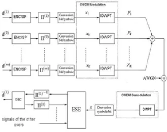
Figure.6 shows the transmitter/receiver structure of an OWDM-IDMA system with K users.
At the transmitter for user-k, the information data is encoded into a sequence ck= {ck[m]}. Each coded bit ckis interleaved by a user-specific interleaver πk, and then the resultant signals, again denoted by Xk(n), are modulated by using IDWPT producing Yk(n), The received signal equals the sum of the signals received from all transmitters. The received signal from K users can be written as:
r(n) = K X k=1 hk(n)Yk(n) + z(n) (11) with Yk(n) = +∞ X n=−∞ M −1 X m=0 xk(n)ψm,n(t) (12) Where hk is the channel coefficient for user-k, z(n) are samples of an AWGN with variance σ2 = N0/2, Yk(n) a chip sequence for user k after OWDM modulation, M the number of sub-channels associated with the transmission, and n denotes the transmission time.
As shown in figure.6, the core of the OWDM-IDMA receiver consists of DWPT for demodulation OWDM, an elementary signal estimator (ESE) and K a posteriori probability decoders (APP DECs). After OWDM demodulation by using DWPT, the iterative processes for receiver IDMA can be applied in the receiver signal r(n) to detect the information data of users. Thus, the iterative process does not include the OWDM demodulation. If the number of paths L is large, this structure reduces significantly the calculation complexity of the receiver.
Information provided to the ESE detector is then the same
Fig. 6. Transmitter/receiver structure for OWDM-IDMA
to retrieve the information from each user, the ESE detector considers only the MAI interferences to allow for removal of the demodulated signal.
V. SIMULATION RESULTS AND DISCUSSION Simulation was done in Matlab. The simulation results are provided to illustrate the performance of OWDM-IDMA systems. For simplicity, we only consider uncoded systems in AWGN channels. K is the number of simultaneous users in the system.
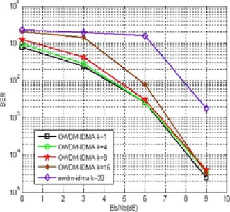
Figure.7 shows the performances of OWDM-IDMA (with ran-domly generated interleavers, a common length-16 spreading sequence for all users and 16 Haar wavelets pulses) in AWGN channels.
BPSK modulation is used by all users and the length of the
Fig. 7. The simulated performance curves for OWDM-IDMA .In this
example, we assume that Information bit length = 3072, iteration number =10, number of users=1,4,8,16,20.
information block is N = 3072 bits per user. The lengths of the spreading sequence is S=16. Here, the performance gain with OWDM-IDMA is mainly attributed to the use of user-specific interleavers, which greatly facilitates the convergence of iterative MUD.
Simulation results (Figure.7) show that the performance of OWDM-IDMA degrades slightly as K increases. This degra-dation is caused by the MAI interferences that become critical when the number of users increases.
The results presented in this section allow us to conclude that for a system OWDM-IDMA, the receiver can effectively mitigate the MAI and ISI interferences by treating them separately. The operation of modulation / demodulation can treat interference ISI, while the detector ESE performs inter-ference cancellation MAI. Therefore, the implementation of a corresponding receiver avoids the iterative processing ISI interference, which a priori reduces calculating complexity.
VI. CONCLUSION
In this paper, we have presented the basic principles of OWDM-IDMA. This system has the advantage of being able to dynamically allocates bandwidth for each of the sub-bands depending on the application (whether it were data for interactive services, video conferencing, audio data, etc) and changing the modulation techniques of each subband to suit the channel.
The main advantage of using OWDM-IDMA relies in the fact that it is a very flexible system which is also simple. In addition, the filter type can be dynamically chosen. It includes low-cost MUD for systems with large numbers of users, robustness and diversity in multipath environnement. In conclusion, OWDM-IDMA appears to be a competitive candidate for future wireless communication systems. We expect that the basic principles can be extended to other applications.
ACKNOWLEDGMENT
This work is supported by The ”Acadmie Hassan II des Sciences et Techniques” and The author wishes to thank the anonymous reviewers for their careful reading.
REFERENCES
[1] Li Ping, L. Liu, K. Y. Wu, and W. K. Leung, ”Approaching the capacity of multiple access channels using interleaved low-rate codes,” IEEE Comm. Lett., vol. 8, pp. 4-6, Jan. 2004.
[2] Li Ping, L. Liu, K. Y, Wu, and W. K. Leung, ”On interleave-division multiple-Access,” in Proc ICC’2004. Paris, France, 2004.
[3] Xin Liu, Xingzhong Xiong, Pingxian Yang ”Modeling and Simulation for IDMA Systems Based on Simulink”, Pacific-Asia Conference on Circuits,Communications and System, 2009.
[4] Li Ping, L. Liu, K. Y. Wu, and W. K. Leung, ”Interleave-division multiple-access,” IEEE Trans. Wireless Commun. Vol. 4, pp. 938-947, Apr. 2006. [5] Li Ping, K. Y. Wu, Lihai Liu et W. K. Leung, .A simple, unified approach to nearly optimal multiuser detection and space-time coding, Information Theory Workshop, ITW’02, (pp. 53-56),Inde, Oct. 2002.
[6] Li Ping, L. Liu, K. Y. Wu, and W. K. Leung, ”A unified approach to multi-user detection and spacetime coding with low complexity and nearly optimal performance,” in Proc. 40th Allerton Conference, Allerton House, USA, Oct. 2002, pp.170-179.
[7] S. Chang, M. Lee and J. Park, ”A high speed VLSI architecture of dis-crete wavelet transform for MPEG-4”, IEEE Transactions on Consumer Electronics, Volume 43, Issue 3, Aug 1997, pp.623 - 627.
[8] Matthieu Gauttier and Joel Lienard, ”Application of Wavelet Packet based Multicarrier Modulation to wireless Transmissions”, ANN.Tlcommun, 62, n 7-8 2007.
View publication stats View publication stats