HAL Id: hal-00012699
https://hal.archives-ouvertes.fr/hal-00012699
Submitted on 26 Oct 2005
HAL is a multi-disciplinary open access
archive for the deposit and dissemination of
sci-entific research documents, whether they are
pub-lished or not. The documents may come from
teaching and research institutions in France or
abroad, or from public or private research centers.
L’archive ouverte pluridisciplinaire HAL, est
destinée au dépôt et à la diffusion de documents
scientifiques de niveau recherche, publiés ou non,
émanant des établissements d’enseignement et de
recherche français ou étrangers, des laboratoires
publics ou privés.
Structure of smectic defect cores: an X-ray study of
8CB liquid crystal ultra-thin films
Jean-Philippe Michel, Emmanuelle Lacaze, M. Goldmann, Marc Gailhanou,
Marc de Boissieu, Michel Alba
To cite this version:
Jean-Philippe Michel, Emmanuelle Lacaze, M. Goldmann, Marc Gailhanou, Marc de Boissieu, et al..
Structure of smectic defect cores: an X-ray study of 8CB liquid crystal ultra-thin films. Physical
Re-view Letters, American Physical Society, 2006, 96 (2), pp.027803. �10.1103/PhysRevLett.96.027803�.
�hal-00012699�
ccsd-00012699, version 1 - 26 Oct 2005
Jean-Philippe MICHEL, Emmanuelle LACAZE,∗ and Michel GOLDMANN
INSP, Universit´es Paris 7 et 6, UMR-CNRS 7588, Campus Boucicaut, 140 rue de Lourmel, F-75015 Paris, FRANCE
Marc GAILHANOU
LURE, Bat 209D, Universit Paris Sud, F-91405 Orsay CEDEX, FRANCE
Marc de BOISSIEU
LTPCM, INPG, BP 75, 38402 Saint Martin d’H`eres, FRANCE
Michel ALBA
LLB, UMR12 CEA-CNRS, CEA-Saclay, F-91191 Gif-sur-Yvette Cedex, FRANCE (Dated: October 26, 2005)
We study the structure of very thin liquid crystal films frustrated by antagonistic anchorings in the smectic phase. In a cylindrical geometry, the structure is dominated by the defects for film thicknesses smaller than 150 nm and the detailed topology of the defects cores can be revealed by x-ray diffraction. They appear to be split in half tube-shaped Rotating Grain Boundaries (RGB). We determine the RGB spatial extension and evaluate its energy per unit line. Both are significantly larger than the ones usually proposed in the literature.
PACS numbers: 61.10.-i,68.35.Bs, 61.30, 68.35.Md
The combined technological interest for liquid crystal (LC) devices and for small size devices requires now a precise understanding of the microscopic structure of liq-uid crystalline films. Progress in the LC physics is often intimately connected to the understanding of the LC de-fects [1]. If now the LC dede-fects are precisely described from a macroscopic point of view, a microscopic descrip-tion is still lacking, with only simuladescrip-tions [2] currently available. The use of powerful techniques such as x-ray diffraction performed with synchrotron radiation sources allows now to bridge such a gap. In lamellar phases (e.g. smectic phases in thermotropic systems), the most com-mon defects are focal conics. They are singularity lines where the layer curvature is not defined, around which the layers rotate. They are ellipses (degenerated into straight lines, the disclinations, in ”oily streaks”) conju-gated with hyperbolae (degenerated into curvature walls, in ”oily streaks”) [1, 3, 4]. The inner structure of these singularity lines, remains unknown since they are buried within the deformed film and only a very small amount of matter is involved. To overcome this first problem, we have studied very thin smectic films in which linear defects dominate the film structure. In this limit, the defects can no longer be considered as singularity lines but are split into two-dimensional structures. We have used oriented samples of ”oily streaks”, self-assembled in regular stripes, and we have performed x-ray diffraction experiments at synchrotron sources that allowed us to determine the rotation of the layers close to the defects. We have revealed the topological structure of the discli-nation core. The spatial extension has been determined and the energy per unit of line estimated. Both values
are at least one order of magnitude larger than the usual estimations proposed in the literature.
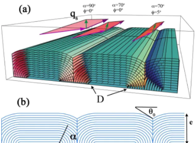
FIG. 1: (a) Scheme of layers, concentrically stacked into flattened hemicylinders lying flat on the substrate, with half disclinations located at points D. Examples of diffusion tri-angles for various α and φ tri-angles are drawn, with enhanced incident angles for clarity, and momentum transfer, ~qs, in green. (b) Flattened hemicylinders, presented in the plane perpendicular to the hemicylinder axes: The curvature walls between neighboring hemicylinders are characterized by the angle at the top, denoted by θ0. The curvature of the layers is associated with the α angle.
We have studied 8CB (4-n-octyl-4’-cyanobiphenyl) smectic films adsorbed on a MoS2 substrate, deformed
through strong antagonistic anchorings at both interfaces but ordered by the single crystal surface of MoS2
(Molyb-denum disulfide). The relaxation of the constraints im-posed by the antagonistic anchorings occurs through the
2
formation of a periodic network of flattened hemicylin-ders, parallel to the substrate [5]. These hemicylinders are associated with half-disclinations locked on the sub-strate at the centers of curvature of the quarters of cylin-ders (points D in figure 1), conjugated with curvature walls.
The 8CB, smectic in bulk at 25o
C, is used without any further purification (BDH-Germany). A 0.1 mol/l solu-tion of 8CB in dichloromethane is deposited on a freshly cleaved surface of MoS2. The film’s thickness, e, is
con-trolled by spin coating at a speed varying between 1000 and 6000 rpm. The film thickness is checked by optical microscopy and determined by the film color, according to the Newton tint table, with an average error of 15 nm in the 70-350 nm range. The sample is annealed at 80oC
to allow the formation of an ordered 8CB/MoS2interface
which imposes a strong planar unidirectional anchoring within large domains [6], antagonistic to the homeotropic anchoring at the 8CB/air interface.
FIG. 2: Bragg intensity variation with φ for different α values (e = 200 nm). The narrowing at small α values reveals a weaker mosaicity and is related to the strong anchoring on the substrate.
X-ray diffraction experiments are performed on the D2AM (ESRF, Grenoble, France) and H10 (LURE, Or-say, France) synchrotron beamlines. The energy is fixed at 8 keV, the beam spot is 50x 50 µm2large. We take
ad-vantage of the periodic character of the smectic A phase and detect the first Bragg peak associated with the 8CB bulk period (qs = 0.198˚A−1). In our resolution limited
set-up, after geometrical corrections (the background is subtracted, the evolution of the beam footprint and of the penetration depth leading to a transmission factor step are taken into account [5] ), the Bragg intensity becomes proportional to the number of layers oriented with the director parallel to the wave-vector, ~qs. The orientation
of the layers is then followed by tilting ~qsand measuring
the evolution of the Bragg intensity. The φ angle is de-fined as the angle between the diffraction plane and the hemicylinder axes. The α angle is defined in the plane perpendicular to the hemicylinder axes as the disorien-tation of ~qs and such as the disorientation of the layers,
with respect to the substrate surface (fig 1b). We have
first checked that the cylindrical symmetry imposed by the anchoring antagonism is preserved within the smectic film whatever the e values: The φ scans of the Bragg in-tensity remain centered at φ = 0, whatever the α values (see fig. 2 for e = 200 nm). We have then measured the Bragg intensity as a function of α for φ = 0, α = 0o
corre-sponding to the layers perpendicular to the substrate and α = 90o corresponding to the layers parallel to it. The
0 0,01 0,02 0,03 0,04 0,05 0,06 0,07 0,08 0 20 40 60 80 Normalized Intensity α(Degrees) 0 0,01 0,02 0,03 0,04 0,05 0,06 0,07 0,08 0 20 40 60 80
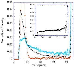
FIG. 3: Bragg intensity variation with α after geometrical correction and background subtraction. Intensity is normal-ized with respect to the integrated intensity from 0o
≤α ≤
85o
. Curves for thin films are shown in the main frame (e = 70, 150 and 200 nm [full triangles, crosses and open circles]), and for a thicker film in the insert (e=450 nm [full squares]).
figure 3 presents the evolution when e decreases from 450 nm to 70 nm. All curves are normalized with respect to the integrated intensity for 0o
≤ α ≤ 85o
. Thus the main frame presents the distribution of rotating layers between α = 0o and α = 85o, for e = 200, 150 and 70
nm. The null intensity from α = 0o to α = 7o is
associ-ated with the 8CB critical angle (θ8CB = 0.17o). When
α becomes smaller than 7o, the incident beam tilt angle
becomes smaller than θ8CBand the beam penetration
be-comes negligible. The rapid increase at 85o
corresponds to the layers parallel to the substrate and is present for all e. In the inset, the quasi-constant Bragg intensity, for e = 450 nm, illustrates that, in case of thick film, only the signal of the bulk organized in flattened hemi-cylinders is detected, associated with a quasi-constant distribution of rotating layers from α = 0o
to α = 85o
[5]. The pronounced evolution of the distribution shape as e decreases, discloses the increasing influence of the half disclination inner structure: The number of rotat-ing layers appears larger at small α than at large α. For very small thicknesses (e = 70 nm), the x-ray signal is controlled by the half disclination structure, leading to Bragg intensity only detected for 7o
≤ α ≤ 25o and at
are measured, indicating that the half disclination size is smaller than 150 nm. The negligible half disclination contribution to the x-ray data, if e = 450 nm, indicates that its size does not vary significantly with the thickness. The gap observed in 70 nm thick films, between flat layers (α = 90o) and rotating ones (7o
≤α ≤ 25o),
as-sociated with the still preserved cylindrical symmetry of the film, allows to model the split mode of the half discli-nation by a Rotating Grain Boundary (RGB). This RGB partitions the parallel layers from the rotating ones (fig-ure 4a) and indeed eliminates a larger number of rotating layers at high α values than at low α ones.
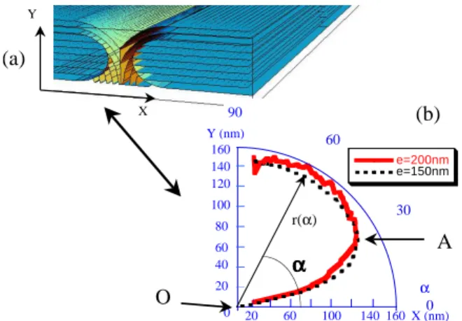
In order to extract the RGB shape from the x-ray data, we define r(α) the polar coordinate of the RGB, taken from the center of curvature, O, of the quarter of cylinder (fig. 4b). Taking in account the curvature walls between the quarters of cylinders, characterized by the upper θ0
angle, defined in fig. 1b, the number of layers n(α) ro-tating from α to α + 1ois evaluated:
n(α) ∝esin θ0 cos α −r(α) for α ≤ 90 o −θ0 ∝e − r(α) for α ≥ 90o −θ0 (1)
The number of layers is also proportional to i(α), the x-ray intensity. The observed high intensity at small α in fig. 3 shows that the RGB spatial extension in the direction associated with α close to 0o
is negligible and the proportionality between n(α) and i(α) is obtained, using a small α0 value, however higher than 7o: n(α0) ∝
(esin θ0
cos α0) ≈ Ai(α0), leading to
r(α) = esin(θ0) cos(α0)( cos(α0) cos(α) − i(α) i(α0)) α ≤ 90 o −θ0 = e(1 − i(α) sin(θ0) i(α0) cos(α0)) α ≥ 90 o −θ0 (2)
We have to estimate now the characteristic θ0 angle.
The observed quasi-constant evolution of x-ray data be-tween α = 50o and α = 85o suggests that θ
0 ≥40o for
200nm ≤ e ≤ 150nm. Postulating a value θ0= 60o, two
similar profiles of the RGB are obtained (figure 4b) for e = 200 nm and e = 150 nm, as expected. These profiles have been extrapolated continuously between α = 7oand
α = 0odown to the O point. They are only slightly
mod-ified, when varying the θ0 value between θ0 = 90o and
θ0= 40o.
The contribution of this RGB profile to the x-ray inten-sity can now be calculated, using the reverse procedure. It is found negligible for e = 450 nm, in agreement with the experimental results. On the contrary, the evolution towards ultra-thin films is driven by the RGB presence. The geometry of films thinner than 80 nm can be de-duced from the profile of figure 4b. They are composed of flat layers alternating with quasi-perpendicular ones, in agreement with the x-ray results on the 70 nm thick film. It should be noted that these high disorientations
0 30 60 90 e=200nm e=150nm (a) Y (nm) X (nm) α r(α) 20 40 60 80 100 120 0 140 0 160 (b) 20 60 100 140 160 O A 90 Y X a
FIG. 4: (a) Scheme of enlarged flattened hemicylinders close to the half disclinations. The arrow associates a schematized half disclination split in RGB with the profile extracted from the x-ray data: (b) RGB profile, as deduced from the x-ray data in cases of thicknesses 150 nm (dotted-line) and 200 nm (line) and a value θ0= 60
o
, presented in the plane perpendic-ular to the hemicylinder axes.
are present whatever the film thickness, since they always exist at the bottom of the buried defects.
The RGB can be described as an half-tube with a quasi-elliptical cut of small axis equal to 140 nm and of half-large axis equal to 110 nm (deduced from fig. 4b). Such a spatial extension is significantly larger than λ, the smectic penetration length, equal to some nanome-ters, the distance usually associated with the focal conic cores in the literature. The origin of focal conic cores is related to the replacement of elastic curvature by dila-tion. A split mode in grain boundaries, characterized by local dilation of the layers, should then be a general prop-erty of focal conics in general. Such a replacement should be independent of the film thickness, as experimentally observed, as well as it should be independent of the an-choring energy values at the interfaces. It should mainly depend on the ratio between the elastic and compression modulus and on the disorientations imposed by the ex-ternal constraints [7], leading to large spatial extensions, similarly for focal conics of different systems.
However one expects the width of the RGB to be of the order of λ. An exact value of the width can not be obtained through x-ray measurements and depends on the detailed structure of the RGB. The RGB is definitely not a simple grain boundary because it can not account for the topological continuity of the layers, contrary to straight curvature walls [7, 8]. Indeed, at point A of the RGB (see figure 4b), 20 flat layers have to accommo-date 45 rotating layers. This necessitates 20 dislocations between the start of the RGB (point O) and point A, as well as between point A and the other RGB extrem-ity. The simplest models for the RGB correspond, ei-ther to a grain boundary with many dislocations (even if they are not detected though x-ray diffraction or optical
4
microscopy measurements [9]), or to a nematic envelope along the RGB [10]. Following these two assumptions, the energy per unit line of the RGB can be calculated and associated to the half-disclination core energy.
In the dislocation hypothesis, this energy is calculated using the energy of a simple grain boundary [8], increased by 40 times the dislocation energy term, of the order of K8CB [3] (K8CB = 11 × 10−12Jm−1 being the smectic
8CB curvature modulus [11]): ERGB = 40K8CB+ 1/2 Rπ 2 0 K λr(α) cos(π 2−α) 2 (tan(π/2 − α)/2 − (π/2 − α)/2)dα = 42K8CB (3)
leading to an energy per unit of line mainly imposed by the dislocations energy.
In the hypothesis of a nematic envelope, the RGB en-ergy can also be estimated, considering that the nematic envelope replaces a smectic envelope whose order param-eter is equal to the smectic bulk order paramparam-eter:
ERGB = PRGB(a2Ψ2(T0−T )s−b4Ψ4)δ
= PRGB(a2(T − T0)2s)/4b)δ
= 108K8CB
(4)
PRGB= 350nm is the RGB perimeter, δ is the thickness
envelope taken as equal to 1 nm, Ψ is the smectic order parameter, T0the transition temperature (T0= 33.5oC),
a and b the second- and fourth-order coefficients, s the critical exponent in the de-Gennes free energy versus Ψ and temperature (a2/b = 3.3 106JK−0.68m−3, s = 0.34
[12]).
These two simple evaluations of the RGB energy are of the same order of magnitude (42-108*K). Improved approximations would call for a finer description of the RGB structure. In the first model, the dislocation distri-bution along the RGB should be taken into account and, in the second model, a continuous evolution of the smec-tic order parameter [13]. These calculations demonstrate that the energy per unit of line is at least one order of magnitude higher than K, the elastic modulus, which is the value usually proposed in the literature for a focal conic core energy per unit of line [14, 15, 16]. On the contrary, this result is consistent with a value of 15*K [8], indirectly obtained from the observations of toroidal focal conics in a lamellar/sponge system. Both results suggest then that disclinations and focal conic core ener-gies per unit of line are closer to 10-100*K than to K, the exact value depending on the geometries of the different systems.
X-ray measurements of thin smectic films deformed through a 90oantagonism of anchoring at both interfaces
have revealed the structure of half disclination cores. They appear to be split in half-tubed Rotating Grain Boundaries (RGB), with a spatial extension of 140x110 nm2 and an energy per unit of line between 40*K and
110*K, K being the elastic modulus. Both values are more than one order of magnitude higher than the val-ues usually proposed in the literature. As for focal conics, the half-disclination structure is imposed by the replace-ment of elastic curvature by dilation. In case of similar ratios between compression and elastic modulus, differ-ent systems submitted to high disoridiffer-entations should also present split modes of the cores in grain boundaries of large spatial extensions. The high energy per unit of line is due to the topological discontinuity of the smectic layers from either part of the RGB. This discontinuity can be accounted either by a grain boundary with a high density of dislocations, or by the presence of a nematic envelope. Such high energies per unit of line could con-stitute a general feature of focal conics and disclinations, whereas only straight grain boundaries allow topologi-cal connections between the layers. Our results not only can be generalized to different defects of lamellar phases (for example, one can think of copolymer or amphiphilic systems that are of fundamental and technological im-portance in many applications) but also demonstrate the ability of x-ray diffraction to probe new soft matter struc-tures. It is now possible, using synchrotron radiation sources, to reveal the detailed inner structure of defects, buried into smectic films.
We thank Maurice Kl´eman and Bernard Croset for use-ful discussions.
∗ emmanuelle.lacaze@insp.jussieu.fr
[1] G. Friedel, Ann. Phys. (Paris) 18, 273 (1922).
[2] S. Mkaddem and E. C. Gartland, Phys. Rev. E 62, 6694 (2000).
[3] M. Kl´eman, Introduction to Liquid Crystals (Les editions de physique, Paris, 1977).
[4] M. Kl´eman, O. D. Lavrentovich and Yu. A. Nastishin Dislocation and disclination in mesomorphic phases (F.R.N. Nabarro and J.P. Hirth, Paris, 2004).
[5] J. P. Michel, E. Lacaze, M. Alba, M. de Boissieu, M. Gail-hanou, and M. Goldmann, Phys. Rev. E 70, 011709 (2004).
[6] E. Lacaze, J. P. Michel, M. Goldmann, M. de Boissieu, M. Gailhanou, and M. Alba, Phys. Rev. E 69, 041705 (2004).
[7] C. E. Williams and M. Kl´eman, J. Phys. C1-sup3 36, 315 (1975).
[8] C. Blanc and M. Kl´eman, Eur. Phys. J. B 10, 53 (1999). [9] M. Ambrozic, S. Kralj, and S. Zumer, Eur. Phys. J. E 8,
413 (2002).
[10] I. Dozov and G. Durand, Europhys. Lett. 28, 25 (1994). [11] M. J. Bradshaw and E. P. Raynes, J. Physique 46, 1513
(1985).
[12] J. Thoen, H. Marynissen, and W. Van Dael, Phys. Rev. A 46, 1513 (1985).
[13] S. Kralj and T. J. Sluckin, Phys. Rev. E 48, R3244 (1993).
[14] P. G. de Gennes, C. R. Acad. Sc. Paris 275, 549 (1972). [15] Z. Li and O. D. Lavrentovich, Phys. Rev. Lett. 73, 280
(1994).
[16] M. Kl´eman and O. D. Lavrentovich, Eur. Phys. J. E 2,