HAL Id: cea-01053380
https://hal-cea.archives-ouvertes.fr/cea-01053380
Submitted on 30 Jul 2014
HAL is a multi-disciplinary open access
archive for the deposit and dissemination of sci-entific research documents, whether they are pub-lished or not. The documents may come from teaching and research institutions in France or abroad, or from public or private research centers.
L’archive ouverte pluridisciplinaire HAL, est destinée au dépôt et à la diffusion de documents scientifiques de niveau recherche, publiés ou non, émanant des établissements d’enseignement et de recherche français ou étrangers, des laboratoires publics ou privés.
Design and optical characterization of a large continuous
phase-plate for Laser Integration Line and Laser
Megajoule facilities
Jerome Neauport, Xavier Ribeyre, Jerome Daurios, Denis Valla, Martine
Lavergne, Vincent Beau, Laurent Videau
To cite this version:
Jerome Neauport, Xavier Ribeyre, Jerome Daurios, Denis Valla, Martine Lavergne, et al.. De-sign and optical characterization of a large continuous phase-plate for Laser Integration Line and Laser Megajoule facilities. Applied optics, Optical Society of America, 2003, pp.2377-2382. �10.1364/AO.42.002377�. �cea-01053380�
Design and optical characterization of a large
continuous phase plate for Laser Integration Line
and laser Megajoule facilities
Je´roˆme Ne´auport, Xavier Ribeyre, Je´roˆme Daurios, Denis Valla, Martine Lavergne, Vincent Beau, and Laurent Videau
For development of the French Laser Integration Line and the Laser Megajoule, we describe the design and the control of a first 383 mm ⫻ 398 mm continuous phase-plate prototype. Extensively used in laser fusion facilities for beam smoothing, this optical component was manufactured by deep etching onto a fused-silica substrate, which led to a phase plate engraved directly onto fused silica, with which good optical performance could be achieved. We demonstrate good agreement between the desired simulated component and the manufactured component in terms of focal spot shape. This demonstration was performed by both interferometric and photometric measurements. © 2003 Optical Society of America
OCIS codes: 140.3300, 220.4840, 120.3180, 120.5240.
1. Introduction
Large laser facilities, such as the Laser Integration Line 共LIL兲, the Laser Megajoule 共LMJ兲,1 or the
Na-tional Ignition Facility,2 nominally produce focal
spots of important size, an order of magnitude beyond the diffraction limit. Moreover the focal spot in-cludes hot spots that are due mainly to the aberra-tions of the important number of large-size optical components used on each laser line 共40 components for LIL and LMJ兲. An indirect drive-fusion-class la-ser needs to deliver a focal spot that limits parametric instabilities of the produced plasma 共Raman and Brillouin backscattering兲. Several smoothing tech-niques were developed for this purpose. Use of a random-phase element for this purpose was first in-troduced by Kato et al.3 A binary two-level 共0, 兲
random-phase plate 共RPP兲 with regular rectangular elements was placed in the plane of the last focusing component of the laser. This RPP created an intsity distribution in the focal plane of the overall en-velope equal to the Fourier transform of the
elementary rectangular element of the RPP. This envelope was filled with a speckle pattern introduced by the random distribution of rectangular elements of the RPP. The speckle pattern can be additionally rapidly moved during laser pulse duration, which can be done by an enlargement of the laser spectrum and the introduction of a dispersive element in the laser such as a grating.4,5 A combination of broad
spec-trum, phase plate, and dispersive element is referred to as smoothing by spectral dispersion and it is basi-cally the smoothing principle that was chosen for the LIL and the LMJ. Figure 1 shows the final optics design of the LIL and the LMJ.6 A broad spectrum
is generated by a sinusoidal phase modulator placed in the front end of the laser. After frequency con-version, the 0.351-m converted light is focused by the 3 grating lens7,8onto the target. Smoothing is
ensured by both the 3 grating lens that serves as a chromatic lens to introduce dispersion along the propagation axis 共longitudinal smoothing兲 and by a phase plate placed 1.25 m behind the vacuum window of the focusing grating. To the best of our knowl-edge, this is the first time that this smoothing prin-ciple is used.
Since Kato et al.3introduced the use of a
random-phase element in 1994, much progress has been made in the field of phase-plate design. Woods et al.9and
Dixit et al.10 replaced the rectangular elements by
hexagonal elements, thus improving the theoretical efficiency of the phase plate from 81.5% to 84%. In an attempt to gain some efficiency and better control
The authors are with the Commissariat a` l’Energie Atomique, Centre d’Etudes Scientifiques et Techniques d’Aquitaine, 33114 Le Barp Cedex, France. J. Ne´auport’s e-mail address is jerome. neauport@cea.fr.
Received 20 September 2002; revised manuscript received 9 Jan-uary 2003.
0003-6935兾03兾132377-06$15.00兾0 © 2003 Optical Society of America
of the focal spot shape, the principle of a multilevel 共16 levels兲 phase plate was proposed by Thomas et
al.11,12 Such phase plates, known as kinoform phase
plates, allow us to couple theoretically 95% of the energy in the desired area and an almost flat-top high-order super-Gaussian envelope. The design of a continuous phase plate 共CPP兲 with a strict contin-uous profile leads to a theoretical efficiency of 100% with a high-order super-Gaussian focal spot enve-lope.13 This last type of phase plate was retained by
the Commissariat a` l’Energie Atomique 共CEA兲 to equip the LIL and the LMJ facilities because of its high efficiency and flexibility.
Here we present the developments that we achieved to calculate, manufacture, and control the LIL and the LMJ phase plates. The CPP involved numerical developments, and the adopted solutions are presented in Section 2. Etching of the phase profile onto a fused-silica substrate was manufac-tured by Jobin Yvon at the request of the CEA. The first prototype 共99-0148兲 was delivered by Jobin Yvon in late 2001. Metrological issues of this prototype, including an original method of wave-front measure-ments by stitching interferometry and direct photo-metric focal spot measurements, are detailed in Section 3.
2. Phase Profile Calculation and Focal Spot Specification
As mentioned above, to gain good energy efficiency we designed a CPP. Here we present the algorithm based on the Gerchberg–Saxton14 iterative
algo-rithm. Figure 2 shows a schematic flow that can be used to obtain a continuous phase. The phase screen is iteratively improved by the repeated prop-agation between the near-field and the far-field planes and application of the near-field and the far-field constraints at each iteration step. This algo-rithm allows us to generate a phase screen to design a high-order super-Gaussian focal plane irradiance profile. It is possible to generate a far-field profile with a higher order than a 10th power super-Gaussian. The principal difficulties of this calcula-tion method is the choice of an initial phase condicalcula-tion and the number of iterations to keep a wrapped phase
screen. We solved the latter problem by choosing an adiabatic modification of the far-field profile when we used the iterative algorithm. To control the flatness of the focal spot is also difficult. To remove the de-formation of the flattop we used a posttreatment that consists of some additional iteration of the algorithm with a far-field mask modified to compensate the ex-act focal spot flat-top deformation. For the calcula-tion we used 256 ⫻ 256 pixels and 4000 iteracalcula-tions. The time and the memory that we used on a DEC Alpha Station were approximately 40 min and 20 Mbytes, respectively. Figures 3共a兲 and 3共b兲 show,
Fig. 1. First-come, first-serve frequency conversion and focusing system 共FCFS兲 optical setup.
Fig. 2. Schematic of the flow of the Gerchberg–Saxton iterative algorithm for the design of CPPs.
Fig. 3. 共a兲 Calculated phase profile in radians. 共b兲 Associated focal spot.
respectively, the result of phase calculation for a cir-cular focal spot and the corresponding focal spot. To control the shape of the focal spot it is important to define all the spot parameters. First, we calculated the average intensity 共I0兲 at the top of the focal spot; second, we calculated the size of the focal spot at 1兾e of I0, 10% of I0, 3% of I0, and the focal spot ellipticity. We also obtained the size at 1兾e and the order of a super-Gaussian fit of the focal spot. The specified parameters are listed in Table 1.
3. Phase-Plate Characterization
The issue was to evaluate the optical performance quality of the 99-0148 prototype phase plate and therefore the agreement of the engraved profile to the specified profile. Two types of metrology were initi-ated for this purpose: photometric-based and interferometric-based measurements.
A. Focal Spot Measurement
The focal spot delivered by the manufactured phase plate was measured by use of the optical setup de-picted in Fig. 4. The 383 mm ⫻ 398 mm phase plate was placed at 1.25 m in the first transmitted order of an 8-m focal-length LIL 3 focusing grating.7 The
grating operates at 25° and measures 420 mm ⫻ 470 mm. This setup is equivalent to the on-line position of the optical component on the LIL. The focusing grating is illuminated with an almost plane wave front delivered by a large 420 mm ⫻ 420 mm square collimator at 351.1-nm wavelength. The collimator consists of a large 460 mm ⫻ 460 mm off-axis parab-ola with a clear aperture of 420 mm ⫻ 420 mm. The focal distance and the off-axis distance of the parab-ola are, respectively, 4.5 m and 300 mm. The resid-ual aberrations of the parabola’s surface are estimated by interferometric measurement at 80-nm peak to valley 共p.v.兲. The parabola was illuminated by an optical fiber by means of an argon laser 共Co-herent Innova 308 C兲. The optical fiber, which was positioned at the focal point of the parabola, delivered 400-mW light at 351.1-nm wavelength. The so-generated plane wave-front is directed toward the
focusing grating by a large 610 mm ⫻ 430 mm mirror 共M1兲 with a clear aperture of 592 mm ⫻ 420 mm manufactured of Sitall glass. The optical reflected wave-front quality of the mirror was measured by interferometry at 67 nm p.v., 9-nm rms at an oper-ating angle of incidence of 25°. A smaller second mirror of equivalent quality was used to deflect the focused beam to the camera. The quality of the wave front delivered to the grating by the parabola and the M1 mirror is estimated at p.v. at 633 nm on a 420 mm ⫻ 420 mm aperture. The focal spot de-livered by this optical system is measured at the best-focus plane with a Hamamatsu ORCA II CCD 12 bit 1280 ⫻ 1024 camera optimized to operate at 351-nm wavelength. The camera is equipped with a microscope objective corrected to 351 nm, so that the pixel delivered by the camera is equivalent to 1.36 m ⫻ 1.36 m in the measurement plane.
Figure 5共a兲 shows the CCD acquisition taken with-out a phase plate; a line portion of this CCD image is shown in Fig. 5共b兲. The energy distribution corre-sponds to the contribution of both focusing grating and collimator residual aberrations. After setting the CPP prototype at 1.25 m of the grating, the en-ergy distribution observed at the best-focus plane is
Fig. 4. Focal spot control setup.
Fig. 5. 共a兲 Image delivered by the 8-m focal-length focusing grat-ing illuminated with a plane wave front at 351-nm wavelength. 共b兲 Plot of the central portion of the image.
Table 1. Focal Spot Specifications
Parameter Specification
Ellipticity 0.90 ⫾ 0.10
Diameter 共small axis兲 at 1兾e I0共m兲 330 ⫾ 20 Diameter 共small axis兲 at 10% I0共m兲 370 ⫾ 25 Diameter 共small axis兲 at 3% I0共m兲 400 ⫾ 50
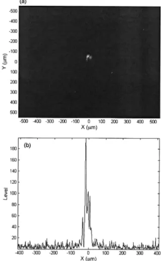
depicted in Fig. 6共a兲; a line plot of the central portion of the image is shown in Fig. 6共b兲. This focal spot was analyzed and fitted with a super-Gaussian irra-diance profile. The result of this analysis is pre-sented in Table 2 and compared with the specifications. Data were presented only for the small axis of the focal spot; both the small and the large axes results are given for the order of the fitted super-Gaussian profile. According to this
measure-ment, the prototype phase plate is in agreement with specifications at 1兾e, 10% of I0, and at 3% of I0. A
super-Gaussian profile of the order of 4.5 is was also achieved for the small axis and 9.6 for the large axis.
B. Stitching Interferometry
Interferometry measurements of large optical compo-nents for laser applications such as the LIL and the LMJ require the use of an installation that responds to two main constraints:
The disposal of a large pupil adapted to the measure-ment of the full pupil of the component 共600-mm diameter in our case兲 on one side.
A high spatial resolution to resolve the small period defects that are close to a millimeter.
We have studied stitching interferometry15for
sev-eral years.16,17 The technique offers a simple,
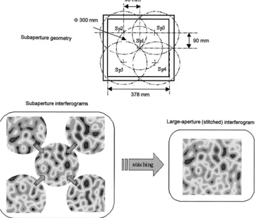
eco-nomical, and usable solution compared with that of large interferometers. Its principle is quite simple. If a component is too large to be measured on its whole clear aperture on an interferometer, the mea-surement decomposed into a subaperture. The wave front is then reconstructed by numerical com-bination of the subaperture measurement by use of recovery areas. Despite some minor constraints, this subaperture metrology offers a higher resolution and dynamic than its large pupil equivalent.18,19
For these reasons, we chose to use a stitching inter-ferometer to measure the wave front of 99-0148 pro-totype the phase plate. The experimental setup consists of the following:
A ZYGO GPI XP HR interferometer that operates at 632.8 nm. The interferometer was equipped with a 300-mm-diameter expander and with a transmis-sion flat transmistransmis-sion reference plate 共300-mm diam-eter, ⬍ 兾20 p.v.兲 mounted on a piezohead. We also used a reflection reference plate made of Zerodur. This plate has the same characteristics as those of the TF plate and conducts to an interferometric cavity of a planeity inferior to 60 nm p.v., 10-nm rms.
Fig. 6. 共a兲 Image delivered by the CPP positioned 1.25 from the focusing grating. 共b兲 Plot of the central portion of the image 共log scale兲.
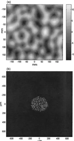
Fig. 7. Transmitted wave front of the 99-0148 prototype phase plate measured by use of stitching interferometry.
Table 2. Focal Spot Analyses from Photometry and Interferometry with the 99-0148 Prototype Parameter Photometric Measurement Reconstruction from Stitching Ellipticity 0.83 0.81
Diameter 共small axis兲 at 1兾e I0共m兲
295 307
Diameter 共small axis兲 at 10%
I0共m兲
372 372
Diameter 共small axis兲 at 3% I0共m兲
446 407
An X-Y scanning mechanical device that allowed the measured component to be shifted in the inter-ferometric cavity. The maximum displacement al-lowed is 1 m and the precision is inferior to 1 mm.
A stitching software named Michael Bray Stitching Interferometer 共MBSI兲 developed by MB Optique Company.
This experimental setup can be used for interfero-metric measurements with a repeatability of some nanometers owing to phase shifting and a sampling rate of 0.7 mm. The setup is optimal for the mea-surement of phase plates with centimeter periods and a maximal slope inferior to 100 rad. The transmit-ted wave front of the phase plate was measured with this stitching interferometer, which is presented in Fig. 7. The complete interferogram was recon-structed from the 300-mm subaperture by use of the MBSI software as depicted in Fig. 8. The p.v. dif-ference between the theoretical and the manufac-tured phase profile is measured at 22 nm for a p.v. of approximately 1.4 m. The reproducibility of the stitching measurements is inferior to 10 nm p.v. and 0.2-nm rms. Some measurements that were taken with six subapertures gave similar results.
The focal spot was reconstructed from the phase measurement by use of the method hereby detailed. If the phase plate were positioned just behind the focus grating, a simple Fourier transformation of the initial field would give the focal spot. In all the focal spot calculations it is important to take into account
the actual phase-plate position, indeed the phase plate is 1.25 m from the focus grating. To include this constraint in our simulation we used the so-called adaptive diffraction: a mathematical trans-formation that allows for calculation of the field between the grating and the best-focus plane.20
In-deed the mesh simulation dimension decreased up to the focal plane. The results of the calculation per-formed on the phase plate measured by stitching in-terferometry is summarized in Table 2. Comparison between direct photometric focal spot measurements and reconstruction from stitching interferometry demonstrate good agreement of both metrology and the manufactured phase-plate component.
4. Conclusion
We have discussed the calculation of a phase plate for beam smoothing on power laser applications. A large 383 mm ⫻ 398 mm phase plate was manufac-tured by Jobin Yvon. We have demonstrated that, by a combination of direct focal spot photometric measurements and focal spot calculations with a stitching interferogram, the component is in agree-ment with our needs. Stitching interferometry ap-pears to be a versatile and useful method for this type of optical component.
We acknowledge G. de Villele, Y. Josserand, J. Fla-mand, and all the Jobin Yvon LIL and LMJ manu-facturing team for their enthusiasms and continuous effort during the development and production of LIL
phase plates. We also acknowledge M. Bray, MB Optique, for his collaboration, availability, and his specific developments with the MBSI software for our application.
References
1. M. L. Andre´, “Status of the LMJ project,” in Solid State Lasers
for Application to Inertial Confinement Fusion: Second An-nual International Conference, M. L. Andre´, ed., Proc. SPIE 3047,38 – 42 共1996兲.
2. W. H. Lowdermilk, “Status of the National Ignition Facility project,” in Solid State Lasers for Application to Inertial
Con-finement Fusion: Second Annual International Conference,
M. L. Andre´, ed., Proc. SPIE 3047, 16 –37 共1996兲.
3. Y. Kato, K. Mima, N. Miyanaga, S. Arinaga, Y. Kitagawa, M. Nakatsuka, and C. Yamanaka, “Random phasing of high-power lasers for uniform target acceleration and plasma-instability suppression,” Phys. Rev. Lett. 53, 1057–1060 共1984兲.
4. R. H. Lehmberg, A. J. Schmitt, and S. E. Bodner, “Theory of induced spatial incoherence,” J. Appl. Phys. 62, 2680 –2701 共1987兲.
5. S. Skupsky, R. W. Short, T. Kessler, R. S. Craxton, S. Letzring, and J. M. Soures, “Improved laser-beam uniformity using the angular dispersion of frequency-modulated light,” J. Appl. Phys. 66, 3456 –3462 共1989兲.
6. A. Adolf, A. C. Boscheron, A. Dulac, and E. Journot, “Final optics design for the megajoule laser,” in Third International
Conference on Solid State Lasers for Application to Inertial Confinement Fusion, W. H. Lowdermilk, ed., Proc. SPIE 3492,
44 –50 共1999兲.
7. J. Flamand, G. de Ville`le, Y. Josserand, F. Bonnemason, B. M. Touzet, and J. Ne´auport, “Development of large aperture 1 and 3 gratings for the LIL laser,” in Large Lenses and Prisms, R. G. Bingham and D. D. Walker, eds., Proc. SPIE 4411, 190 – 196 共2001兲.
8. J. Ne´auport, P. Bouchut, J. Flamand, G. de Ville`le, Y. Josser-and, F. Bonnemason, B. M. Touzet, P. Garrec, X. Ribeyre, and G. Chabassier, “Large transmission 1 and 3 gratings for the LIL laser,” in Physics, Theory, and Applications of Periodic
Structures in Optics, P. Lalanne, ed., Proc. SPIE 4438, 41–50
共2001兲.
9. B. W. Woods, I. M. Thomas, M. A. Henesian, S. N. Dixit, and
H. T. Powell, “Large-aperture 共80-cm diameter兲 phase plates for beam smoothing on Nova,” in Solid State Lasers II, G. Dube, ed., Proc. SPIE 1410, 47–54 共1991兲.
10. S. N. Dixit, I. M. Thomas, B. W. Woods, A. J. Morgan, M. A. Henesian, P. J. Wegner, and H. T. Powell, “Random phase plates for beam smoothing on the Nova laser,” Appl. Opt. 32, 2543–2554 共1993兲.
11. I. Thomas, S. N. Dixit, and M. C. Rushford, “Kinoform phase plates for focal plane irradiance profile control,” Opt. Lett. 19, 417– 419 共1994兲.
12. I. M. Thomas, S. N. Dixit, and M. C. Rushford, “Preparation of random-phase plates for laser-beam smoothing,” in
Laser-Induced Damage in Optical Materials: 1994, H. E. Bennett,
A. H. Guenther, M. R. Kozlowski, B. E. Newnam, and M. J. Soileau, eds., Proc. SPIE 2428, 264 –270 共1994兲.
13. “Distributed phase plates for super-Gaussian focal-plane irra-diance profiles,” LLE 共Laboratory for Laser Energetics兲 Rev. 63,126 –129 共1995兲.
14. R. W. Gerchberg and W. O. Saxton, “A practical algorithm for determination of phase from image and diffraction plane pic-tures,” Optik 35, 237–246 共1972兲.
15. J. Tsujiuchi, M. Otsubo, and K. Okada, “Measurement of large plane surfaces shapes by connecting small-aperture interfero-grams,” Opt. Eng. 33, 608 – 630 共1994兲.
16. M. Bray, “Stitching interferometer for large optics: recent developments of a system,” in Third International Conference
on Solid State Lasers for Application to Inertial Confinement Fusion, W. H. Lowdermilk, ed., Proc. SPIE 3492, 946 –956
共1998兲.
17. M. Bray, “Stitching interferometry: how and why it works,” in Optical Fabrication and Testing, R. Geyl and J. Maxwell, eds., Proc. SPIE 3739, 259 –273 共1999兲.
18. M. Bray and A. Roussel, “Using first principles in the specify-ing of optics for large high-power lasers 共I兲: application to the Megajoule laser 共LMJ兲,” in Specification, Production, and
Test-ing of Optical Components and Systems, A. E. Gee and J.
Houee, eds., Proc. SPIE 2775, 328 –344 共1996兲.
19. M. Bray, “Stitching interferometry: side effects on PSD,” in
Optical Manufacturing and Testing III, H. P. Stahl, ed., Proc.
SPIE 3782, 443– 452 共1999兲.
20. J. A. Fleck, J. R. Morris, and M. D. Feit, “Time-dependent propagation of high energy laser beams through the atmo-sphere,” Appl. Phys. 10, 129 –160 共1976兲.