HAL Id: hal-00603361
https://hal.archives-ouvertes.fr/hal-00603361
Submitted on 24 Jun 2011
HAL is a multi-disciplinary open access
archive for the deposit and dissemination of
sci-entific research documents, whether they are
pub-lished or not. The documents may come from
teaching and research institutions in France or
abroad, or from public or private research centers.
L’archive ouverte pluridisciplinaire HAL, est
destinée au dépôt et à la diffusion de documents
scientifiques de niveau recherche, publiés ou non,
émanant des établissements d’enseignement et de
recherche français ou étrangers, des laboratoires
publics ou privés.
Dynamic behavior of an aggregate material at
simultaneous high pressure and strain rate: SHPB
triaxial tests.
Patrice Bailly, Franck Delvare, Jean-Luc Hanus, Jérôme Vial, Maxime Biessy,
Didier Picart
To cite this version:
Patrice Bailly, Franck Delvare, Jean-Luc Hanus, Jérôme Vial, Maxime Biessy, et al..
Dynamic
behavior of an aggregate material at simultaneous high pressure and strain rate:
SHPB
tri-axial tests..
International Journal of Impact Engineering, Elsevier, 2011, 38 (2-3), pp.73-84.
�10.1016/j.ijimpeng.2010.10.005�. �hal-00603361�
Dynamic behavior of an aggregate material at simultaneous high
pressure and strain rate: SHPB triaxial tests
P. Bailly1, F. Delvare1, J. Vial1,2, JL. Hanus1, M. Biessy2, D. Picart2 1
ENSI Bourges, Institut PRISME, F-18020 Bourges, FRANCE
2
CEA, DAM, Le Ripault, F-37260 Monts, FRANCE
Abstract
Low velocity impacts on energetic materials induce plastic deformations and sliding friction which can lead to ignition. If some ignition criteria have been proposed, the remaining difficulty is to characterize the mechanical behavior of the material when submitted to the corresponding solicitations (high pressure and high strain rate). Thus, a technique based on the Split Hopkinson Pressure Bars system is proposed to carry out a triaxial compression test. A cylindrical specimen is placed into a confining ring and is compressed by the system of bars. The ring prevents the radial extension of the specimen and creates a lateral confining pressure. The material and dimensions chosen for the ring maintain a constant radial pressure during the test. Some tests were carried out on an inert aggregate material and proved the validity of this experimental device. The experimental data processing shows the influence of both the pressure and the strain rate. The shear stresses, which contribute to thermal dissipation and then to the ignition threshold, increase according to the pressure.
1.
INTRODUCTION
Understanding high explosive ignition is necessary for safety reasons, whatever the unforeseen situations. The response of HMX-based explosive compositions to a dynamic mechanical solicitation, such as a projectile impact, is still not understood. For projectiles with high kinetic energy, the shock-to-detonation transition threshold is reached and leads to a violent reaction. When the projectile velocity decreases, a lesser reaction, such as a deflagration or combustion, is obtained. Lastly, no reaction is observed for low velocities, usually close to 50-100 m/s depending on the targets, projectile shapes and energetic materials. Efforts have been made to characterize such a behavior using as simple experiments as possible (drop-weight tests [1], Steven-tests [2]). The resulting data were used to complete safety studies of pyrotechnic systems. Unfortunately, unexpected results occurred, such as for example (1) the difficulty in determining the sensitivity of various energetic molecules submitted to the same drop-weight standard test or (2) an increase of the ignition time with the projectile velocity for given Steven test-like experiments [3]. Considering the variety of impact conditions (projectile shape, kinetic energy, amplitude and direction of the projectile velocity), the variety of pyrotechnic structures (confinement or not of the high explosive material) and of energetic materials, phenomenological or physically-based models are needed to replace empirical predictions.
The desired predicting tool has to combine a numerical code, a dynamic mechanical constitutive law, an ignition criterion and experiments to calibrate these models. The numerical code is needed due to the heterogeneity of the stress, the strain and the strain rate on the pyrotechnic structure during an impact. A simple analytical determination of the mechanical response is still hardly tractable. On the other hand, ignition is a thermally activated process. If the kinetic decomposition schema is easily considered, the mechanical-to-thermal microstructural conversion mechanism has to be determined and modeled taking into account the macroscopic mechanical fields. Unfortunately, such a material exhibits complex behavior. Damage by micro-crack growth and coalescence has been widely investigated in the literature. This deformation process essentially develops for low confinement configurations. If higher hydrostatic pressure develops in sample, plasticity of the constituents can be observed. Lastly, strain localization and failure have been reported, resulting in extreme impact loading conditions. At the laboratory scale, improvement of the constitutive laws is still difficult due to the intensity of stress and strain rates during impact, compared with the limitation of available experimental techniques. This paper details an extension of the well-known triaxial experiment at dynamic conditions encountered during an impact.
Loading conditions were determined by studying impact experiments of a 1.2 kg-projectile on a high explosive contained in a metallic shell [4-6]. Different shells were used ensuring front and back confinements of the target (Figure 1). The front plate was thin (less than 5 mm) whereas a thicker back
plate was used to limit back face displacement. The target was laid on a V-block to simplify the boundary conditions and, thus, the simulations. Lastly, the shape of the projectile nose was varied (hemispherical, flat…). This test was repeatable and enabled the determination of the velocity threshold leading to a reaction of the high explosive sample. An example of signals is given in Figure 2. Gauges were glued at the centre of the target and at a point outside the projectile impact area. The projectile velocity was equal to 77 m/s. The first signal appeared at the centre of the target (red signal on Figure 2). The pressure was about 140 MPa. Nonetheless, 150 µs after impact, the pressure increased and reached a maximum of 600 MPa. The fall in pressure that directly followed the peak could be the consequence of the opening of the target, or of a significant deformation of the front plate. Lastly, the end of the signal indicated gauge failure with the pyrotechnic reaction of the high explosive. Gruau et al. [7] performed some numerical simulations of these experiments. To this end, they developed a numerical tool based on the ABAQUS/Explicit finite element code and a concrete-like constitutive property for the high explosive [8-9]. Gruau and Picart [10] determined the material parameters. The simulation of the configuration reported in Figure 1 exhibited a mean plastic strain rate of 105 s-1, a maximal pressure close to 500 MPa and a finite strain approaching 0.5.
Split Hopkinson’s pressure bars (SHPB) are now widely used to characterize the dynamic behavior of materials. A uniaxial compression can be generated in a long bar (here called the input bar) using a projectile. This wave is partially transmitted to the sample placed between the input and the output bars. When the input and output forces are equilibrated (meaning equal), measurements give the stress-strain evolution. Data can be found in the literature for concretes, rocks and geomaterials [11-12], and for high explosives submitted to a solicitation with a strain rate of a few thousands per second [13]. On the other hand, high quasi-static triaxial tests have been widely used to determine the pressure dependence of the behavior. Usually, pressure is applied using a fluid (water, oil) compressed by a hydraulic machine. The sample surrounded by the fluid is subjected to a hydrostatic load. Then, a uniaxial compressive load is applied using a piston to impose a deviatoric stress to the sample. Data obtained on high explosives are proposed in [14-18]. Unfortunately, only a limited number of researchers have put together the two techniques to study the influence of both high pressure added to high strain rate.
Two classes of devices are used to work out a dynamic compressive test on a confined specimen. For the “pressure cell” device, the specimen is introduced in a cylindrical quasi-static pressure cell. The bars act as pistons and are introduced in the cell through sealing rings [19]. The lateral pressure can be applied using oil, or water (up to 50 MPa) or using air (up to 10 MPa). In [20-21], a confining cell is used to compress air around the sample placed between the bars and the air pressure is constant during the test. With oil, the pressure is not constant, because of the transient effect of the fluid. It is not sure that a measurement of the oil pressure during the test at a point of set up would give an exact measure of the pressure applied to the specimen. For the second device, confining pressures were obtained by placing the specimen in a metallic sleeve to achieve passive confinement. There are two ways of performing the compressive test. The metallic ring can be compressed with the specimen [20, 21]. This method needs careful sample preparation and the use of a strain gauge on the ring. It allows the simultaneous measurement of the radial pressure and strain of the specimen. Unfortunately, it is impossible to verify the lateral pressure. This method is restricted to the case of thin metallic rings and the compressive force acting on the specimen is not be negligible compared to the force acting on the ring. Consequently, this method is limited to low pressure confinement and to material having a higher Poisson’s ratio than that of the metal constituting the ring. On the other hand, the compressive stress can be applied directly on the specimen. The metallic ring is then subjected to internal pressure due to the lateral expansion of the specimen. This technique has been used for quasi-static tests [22-23] and for dynamic ones [24-26]. The elastic behavior of the steel ring, and the analytical solution of a hollow cylinder submitted to inner pressure, would enable us to deduce the pressure on the inner surface knowing the cylinder deformation recorded at the outer surface. This technique is not directly usable here because (1) constant confining pressure cannot be ensured during a part of the test, (2) the sliding strains are negligible, and (3) shear fracture does not necessarily occur. The set-up proposed in this paper solves such a difficulty by a modification of the passive ring method.
To develop this specific experiment and because we are approaching conditions leading to ignition, an inert stimulant material, denoted I1, was used. The mechanical properties of I1 are quite similar to those of energetic materials [17,27-28]. Recovered targets showed similar trends on the mechanical response of inert and energetic materials (Figure 3). I1 was completely crushed at the centre and had flowed out of its bearing surface while breaking into pieces. Thus, two damage mechanisms occurred in the target. At the centre, I1 was submitted to highly confined triaxial compression, whereas only simple compression or even tensile stress was observed on the edges. Radial and circumferential macro-cracks were observed, showing the high heterogeneity of the deformation process.
A brief description of I1 is proposed in Section 2 of this paper. Then, the experimental set-up is detailed in Section 3, followed in section4 by a discussion of the main results obtained on I1. These data enable the behavior of this inert material to be determined when it is submitted to high confinement, finite strain and high strain rate.
2.
MATERIAL
Material I1 is an aggregate composite manufactured by hot hydrostatic press molding. The solid fraction of crystal is composed of 29.3 %wt of barium meal (BaSO4) and 65.2 %wt of melamine. The binder is of a small amount, 5.5 %wt. It is made of an epoxy resin and a blue pigment. The final material is manufactured in three stages. The first stage enables the different constituents to be blended into a solvent. A chemical agent is added to granulate the particles into small spheres of 1 mm in diameter. These balls are then put into a flexible bag. The loose packed material is pressed using a hydrostatic cell, by means of three compression cycles up to a pressure of 150 MPa, at a constant temperature of 80°C. Lastly, the sample is heated to a temperature of 120°C for several hours to polymerize the binder. The resulting material has a mean density of 1.73 with a high residual porosity of 28 %.
The mechanical properties of I1 are illustrated in Figure 4 for quasi-static compressive and tensile tests. Experiments were performed using a strain rate close to 10-4 s-1 for the compressive condition (respectively 10-5 s-1 for the tensile condition). A compressive strength of 27 MPa was recorded, corresponding to a strain of 2.5 %. For tensile stress, the strength did not exceed 5 MPa for a strain of 0.4 %. Like concretes, I1 exhibits a ratio between unconfined compressive and tensile maximum stresses close to 5. Softening in compression was also observed. Momber [29] studied failures of concretes when subjected to compressive load. He showed that the bonds between particles and matrix fail first, before macro-cracks into the matrix appear and quickly develop. From the moment when the ultimate strength is reached, secondary fracture debris is randomly generated, explaining non reproducible measurements in this part of the test. The unconfined compressive ultimate strength increases with strain rate (Figure 4). A sudden evolution of the slope is observed around 10-100 s-1, the strength recorded at 1000 s-1 being approximately 5 times the strength at 10-4 s-1. The same observation was made for high explosive behaviors [30-31]. The mechanisms governing this evolution are not yet fully understood.
Scanning electron microscopy (SEM) observations of I1 were made. The surface of the sample was polished with an abrasive paper of 2400 and with a liquid suspension containing 1 µm alumina particles. Finally, the surface was gold-colored under vacuum. On Figure 5, barium meal crystals appear to be grey with a size ranging from 1 to 100 µm. A clearer “material” was observed between these crystals that may contain melamine crystals and binder. Since melamine is very resistant to abrasion, a relief remains in those areas. Figure 5 enables the comparison to be made between the pristine I1 and the same material after biaxial compression (uniaxial compression with no displacement in one of the two transversal directions). Melamine crystals seem to be unbonded and scattered over the whole surface. The shape of barium meal crystals was not changed, though some of them were broken. Nonetheless, in regions with poor binder density, such as on the right side of Figure 5, these crystals had supported all the local stress and had broken into several pieces.
3.
DYNAMIC TRIAXIAL SET-UP
Impact experiments and numerical simulations clarified the loading solicitations which have to be experimentally approached. A confining pressure ranging from 300 to 500 MPa is expected, as well as finite strain up to ten of per cent. A strain rate exceeding 104 s-1 being unreachable using SHPB, our attention focused on 103 s-1. The proposed test was designed to cause a high sliding strain during a constant confining pressure stage, and with an almost constant strain rate. When confinement was realized using an elastic steel ring, the radial strains were negligible compared to the axial ones. This test is considered as quasi-oedometric (no transversal displacement) and the loading path is given by the following relation:
ν + ν − = 1 2 1 P 2 Q
(1)
where P and Q respectively denote the pressure (the mean stress or the hydrostatic stress) and the octahedral shear stress. If S is the deviatoric part of the stress tensor σσσσ, P and Q are given by the following relations: σσσσ trace 3 1 P= SSSS = σσσσ−P 1111 SSSS SSSS : 3 1 Q=
(
)
(
)
σ − σ = σ + σ = 2 1 2 1 3 2 Q 2 3 1 P (2) with the axial stress denoted σ1 and the radial stress σ2. 1 is the second-order unit tensor and trace is
the summation of the diagonal terms of a tensor. The knowledge of Poisson’s ratio ν of I1 (about 0.42)
enables the determination of the loading path in a uniaxial (simple) compression: Q = 0.22 P. At low strain rates, the behavior of I1 was studied under high confining pressures and led to the following shear strength criterion: Q = 12 + 0.3 P (MPa). A small internal friction coefficient value was obtained probably due to the presence of the binder. The two previous equalities show that the shear resistance criterion cannot be reached by a quasi-oedometric test. Assuming an elastically deformed ring, the loading path is given by the following relations:
(
)
(
)
(
2)
1 2 2 C 2 2 C 2 1 C C 2 C 2 R R E R 1 R 1 S S − ν + + ν − = σ − = ε(3)
(
)
C C S E 1 S E 2 1 2 P Q + ν + + ν − =(4)
where the subscript c denotes the ring material parameters and Sc denotes the ring stiffness. εi is the strain recorded in the i-th direction. E is the Young’s modulus of the material I1 and Ec is the Young’s modulus of the material of the ring. For a steel ring with an inner diameter of 2 R1 = 5 mm and an outer diameter of 2 R2 = 10 mm, again the slope of the Q-P curve is less than the friction coefficient. In order to obtain a conventional triaxial test, a confining ring made of a perfectly plastic material can be used. A plastic zone located in the inner radius of the ring appears and propagates to the outer surface, when the inner pressure increases. When all the material of the ring yields, the ring deforms infinitively for the given inner pressure. Thus, inversely, a constant confining pressure can be maintained at the lateral boundary of the sample. Figure 6 gives the different loading paths. OC is the usual loading path followed during a uniaxial compressive test. The line OA corresponds to an elastic deformation of the ring. This line is close to an oedometric loading path. The line AB corresponds to the useful and last part of the test, when the ring is totally plastified.
For each test, a single-use ring was used and the knowledge of the elasto-plastic behavior of the ring material was required. Rings with different thicknesses were used to obtain several values of the confinement pressure. The assumption of elastic perfectly plastic behavior is very important for the accurate determination of the inner pressure. Brass was chosen due to its elastic quasi perfectly-plastic behavior at high strain rates [32]. Static and dynamic experiments were conducted to verify this assumption. During this dynamic test the strain rate varies between 50s-1 and 150s-1. This strain rate is representative of the strain rate in the brass ring during the triaxial dynamic test. Indeed when the axial strain rate in the material tested is about 1000 s-1, the circumferential strain rate in the ring, at the yield stress, is about 50 s-1.The results are presented on figure 7. As expected, the Young's modulus remains constant, the strain rate affects the yield stress and the hardening. There is less than 5% of strain hardening and it will be neglected.
The SHPB system, also called Kolsky's apparatus, is a commonly used experimental technique to study materials at high strain rates. The specimen is a cylinder whose diameter and height are equal to 10 mm. The SHPB system is composed of an input bar and an output bar with the short specimen placed between them (Figure 8). When the striker strikes the input bar at its free end a compressive longitudinal incident wave is generated. Once this incident wave reaches the interface between the specimen and the bar, a reflected wave appears in the input bar and a transmitted wave (through the sample) in the output bar. Strain gauges are glued on the input and output bars and allow the measurement of these three basic waves. The bars, made of hard steel (the elastic yield is 1000 MPa), have a diameter of 20 mm. The input bar is 3 m long, the output bar is 2 m long and the striker is 1.2 m long. The length of the striker and the strain gauge positions allow a test duration of about 400 µs. Forces and velocities at both faces of the specimen can be deducted from incident,
transmitted and reflected waves. Two additional transversal gauges are glued onto the brass ring. These gauges give the radial strain of the ring. From these measurements and with the assumptions of a perfect elasto-plastic behavior of the brass ring, the lateral pressure acting on the specimen can be estimated.
Data processing of the waves is made using a software, including wave dispersion correction and an assisted time shifting method based on the elastic transient response of the specimen [33]. The following relations give the velocities and the forces at both ends of the specimen:
)
t
(
C
)
t
(
V
))
t
(
)
t
(
(
C
)
t
(
V
t B o r i B iε
=
ε
−
ε
=
)
t
(
E
S
)
t
(
F
))
t
(
)
t
(
(
E
S
)
t
(
F
t B B o r i B B iε
=
ε
+
ε
=
(5)where subscripts i and o refer to input and output bars velocities and forces. CB, SB and EB are respectively the celerity of elastic waves, the cross-section and the elastic Young’s modulus of the bars. The three strain waves measured using gauges are the incident, reflected and transmitted
waves (Fig. 9).With the assumption of homogeneity of the stresses and of the strains in the specimen,
the mean axial strain ε1 and the mean strain rate ε&1 are given by the following relations:
( )
(
U( )
t U(t))
L 1 t 0 i l = − ε( )
=∫
t( )
τ τ 0 i i t V d U( )
(
V (t) V(t))
L 1 t o i 1 = − ε&(6)
where L is the length of the specimen, and Ui and Uo the displacement of the two sides of the specimen. The axial stress (σ1) is estimated from the force measured by the output bar (σ1s) or from
the mean of both forces measured by the output bar and by the input bar, (σ1m)
( )
t F S 1 ) t ( o s 1 = σ(
F( )
t F( )
t)
S 2 1 ) t ( i o m 1 = + σ(7)
with S the sample cross-section. The homogeneity of the axial stress is checked for same forces at the two ends of the specimen. A stress-strain relation and a loading path can then be derived.
Before deducting the confining stress from the circumferential strain measurement of the ring, a shift in time is necessary using a comparison between the axial stress and the axial strain. This calibration is performed considering that (1) the confining stress appears at the same moment as the axial stress and (2) the behavior of the specimen and of the ring are initially elastic. The ratio between the axial stress and the lateral stress is thus close to:
ν − ν = σ σ 1 1 2 (8) However, the axial and the lateral stresses are almost constant when the ring is completely plastified. An error in shifting the beginning of the different signals has no effect on the stress states estimated during the useful phase of the test (Figure 12 shows that constant stresses are obtained). The determination of the lateral confining stress is derived from a mechanical model of the ring. The parameters influencing this model are (1) the height of the ring which is equal to or greater than the length of the specimen, (2) the friction between the specimen and the ring and (3) the behavior of the material constituting the ring which is elastic or elasto-plastic.
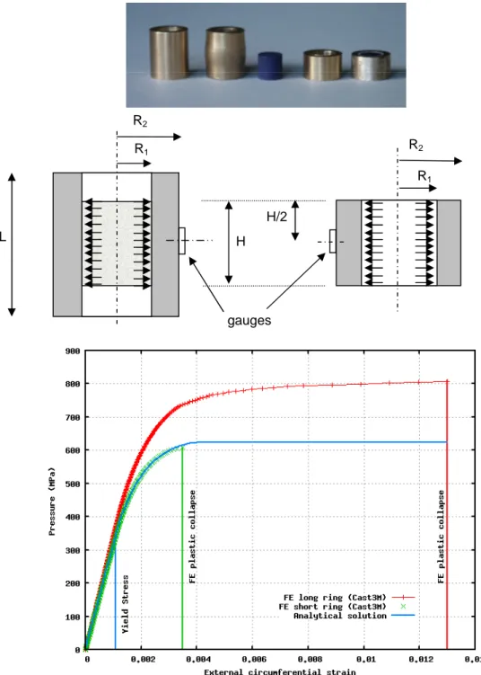
Several authors, as [34], have used an elastic ring longer than the specimen. In this case the determination of the lateral stress requires some gauges along the height of the ring, numerical modeling or approximations so as to deduce, from the shape of the ring, the pressure distribution along the inner diameter of the cylinder. When the ring and the specimen are of the same lengths, and if friction is neglected, the elastic cylinder can be considered in a plane stress state similar to that described by Lamé’s cell. Reference [34] has also shown that if the ring is longer than the specimen, Lamé’s solution is an inaccurate approximation. In this paper, the ring carrying the passive confinement is plastified. Assuming the Tresca criterion, the problem has an analytical solution for perfect elasto-plastic behavior and plastic incompressibility. This analytical solution is resumed in Table 1 and details are in Appendix. To validate this model, two heights were used (for the same sample sizes). The photograph (Figure 9) shows the two rings before and after the test. The
assumption of a plane problem is clearly not verified for the longer ring. For the short ring, the axisymmetry was preserved after the test and the plastic strain only increased the diameter of the ring while its height was unchanged. In this case, the analytical solution seems acceptable.
As a confirmation, finite element simulations were performed using Cast3M1 code which is a general purpose code for solving partial differential equations by the finite element method. The finite element simulations assume an axisymmetric stress and strain field and a Von Mises plasticity model without work hardening. Due to symmetry conditions, only one quarter of the ring cross section was modeled. The bi-dimensional model was meshed using second-order quadrangular eight nodes finite elements. The regular meshes are composed of 400 elements (2562 degrees of freedom) for the short ring and 800 elements for the longer one. The load was applied by a prescribed uniform monotonic increasing pressure on the inner surface of the mesh. Figure 10 shows the relationship between the outer circumferential strain and the confining stress. For the longer ring, the analytical solution is an unacceptable approximation when the ring is plastified. In contrast, as expected, the short ring finite element result corresponds to the analytical solution. Furthermore as observed in Figure 11 , the stress field is inhomogeneous along the height for the longer ring. The use of a long ring, even with several gauges, would require very precise specimen positioning within the ring which would be very difficult to asses. Thereafter, only the configuration using short rings was retained.
This configuration requires the use of guide bushings to ensure that the compression of the specimen, the ring and the cap are coaxial (Figure 7). The rings used and the corresponding maximum confinement pressure are presented in Table 2.
4.
RESULTS AND DISCUSSION
Data processing has firstly been detailed for one experiment made using a ring with an outer diameter of 14 mm. The raw signals recorded for this experiment are those presented in Figure 9. Evolutions of the axial and radial strains and of the two stresses were obtained versus time (Figure 12). Two (respectively three) square dots are plotted along each stress (respectively strain) curve. The first dot appearing on curves shows the moment when the ring is fully plastified. Then, the sample was submitted to a conventional triaxial loading state and we entered the “useful phase” of the test. The second dot is the end of the reliable measurement of the radial strain of the sleeve corresponding to the “theoretical” limit of the gauge (maximum strain: 0.03). Sometimes experiments enabled the measurement of higher lateral strain, when some gauges became unbonded due to excessive elongation. But, knowing the quasi-perfect plasticity of brass and its strain rate independence, the constant confining pressure measured before the gauges became unbonded can be prolonged. The latter dot corresponds to the final stress state (maximum axial stress) and the end of the given experiment.
The combination of strain and stress over time enables the determination of the stress-strain
curve (Figure 13). During the useful phase of the test, estimation of the axial stress σ1S was close to
σ1m meaning that (1) the input and the output forces were almost equal, and that (2) the assumptions
of quasi-static equilibrium of the specimen and of the uniformity of the stress distribution in the specimen were valid. Before the first dot, these assumptions were not verified as is demonstrated in Figure 13. A slight evolution of the lateral stress was recorded ensuring a quasi-constant confining pressure. Figure 13 shows the axial strain rate versus the axial strain. During the useful phase of the test, this strain rate is almost constant and approaches 700 s-1. Loading paths obtained using the same confinement method but with various strain rates can be compared. Quasi-static measurements were made at 10-2 s-1 using a compressive machine. Figure 14 gives the loading paths in the P-Q diagram (in terms of stress) and in the ∆V/V−γ diagram (in terms of strain). A triaxial loading path
was reached, whose slope is 2 in the P-Q diagram, and its intersection with the horizontal axis gave
a confining pressure of Pc = 130 MPa. Before that, a hieratic evolution was registered, probably governed by initial residual gap between the sample and the ring, material/ring friction conditions and set-up positioning between the bars. To minimize the initial gap, the inner diameter of the sleeve is 0.01 mm less than the outer sample diameter. Samples were forced into rings. Volumetric and distortional strains are defined as ∆V /V =
(
ε1+2ε2)
and γ = 2(
ε1−ε2)
/3. During the early stage of thedeformation process, the elastic ring limits the lateral strain. The distortion is thus 2/3 times the dilation. As the ring deforms, the sample is submitted to a constant lateral stress, the deviatoric stress (respectively the distortion) being related to the hydrostatic pressure (respectively dilation) by a 2
1 The FE code Cast3M is developed by the Department of Mechanics and Technology (DMT) of
factor. These slopes are observed in Figure 14.
Three main observations can be made from our experimental database:
- The two gauges bonded on the confining rings have always given similar data. The residual dimensions of the rings has shown that plasticity has developed. Diameters increased when the heights remained unchanged. The residual shape is still a cylinder.
- Dispersion of results can be due to (1) measurement inaccuracies, (2) approximations made during the analysis and (3) to the variability of the material parameters. During the quasi-static tests, low variability was observed. The material is perfectly homogeneous due to its composition and the method used for manufacture. The experimental device in itself, and especially the manner in which the ring is machined, could introduce such a dispersion. A set of ten dynamic tests were performed to observe dispersion. The imposed velocities of the SHPB projectile were substantially the same. The results showed a reproducible response of the material I1. The derived ultimate stress showed a maximum deviation of 5% (crosses have been added to Figure 16 to highlight such a dispersion). This deviation is low for this kind of dynamic test. The worst reproducibility came from the transverse strain measurements, especially at the end of the test.
Friction between the ring and the material tested is a usual problem for this kind of experiment. If the friction is not negligible, it would affect the axial force and the determination of the axial stress. An evaluation of the static friction coefficient gave a value of about 0.1, but this evaluation is not sufficient to estimate the friction force in the dynamic test. In order to identify the influence of the friction, we have made some additional tests when the rings and the samples used were shorter (both heights were equal to 5 mm). No effect on the axial force was noticed during these experiments. It seems, in this case, that the binder of the material tested acts as a lubricant. That negligible effect of the friction is a necessary assumption for the validity of the analytical method used for processing the test.
Figure 15a shows the spherical part of the behavior of the material for different strain rates. A mean bulk modulus K equal to 4000 MPa is measured and this shows no pressure dependence. Nor is a significant dependence on the strain rate observed. A small plateau is observed during the ultimate phase of the test, corresponding to the final part of the triaxial test (constant pressure and deviatoric stress). The pressure is constant and a slight compaction is recorded due to the distortion strain. The plateau is not observed for all the experiments. Material I1 is able to deform at constant pressure and volume. Figure 15b shows the deviatoric part of the behavior of the material for different strain rates. A strain rate dependence of the deviatoric stress is observed when quasi-static responses are compared to dynamic ones. Moreover, in the dynamic domain experimental variations are observed during the test (a shear modulus can not be deduced). It is impossible to determine the elasticity threshold using this data set. The threshold is exceeded before force equilibrium and “pure” triaxial conditions are achieved. The corresponding high explosive has been widely studied at low strain rates [17]. A small (visco)-elastic domain is determined. This behavior is followed by a long (visco)-elasto-plastic domain up to the ultimate stress. We are only interested here in this second stage of the deformation process.
Figure 16 gives the ultimate confined stress in the P-Q plane, for all the configurations of the test. The ultimate stresses are deduced with Figure 12-right or 13-left as the maximum value reached during the last plateau. Measurements are aligned along parallel lines, respecting the constant confining pressure imposed using the given sleeve geometries. Data have been gathered on three typical strain rates. The line labeled “100/s” takes into account strain rates varying between 80/s and 200/s. On the line labeled “1000/s”, the strain rate varies between 700/s and 1200/s. The mean dispersion is represented using a cross for each data. The pressure dependence of the plastic criterion is illustrated by quasi-static measurements. A cohesive stress (intersection with the Q axis) and the internal friction (slope of the threshold) are respectively equal to 12 MPa and 0.30. These values are close to measurements obtained on concrete or rocks [19-20]. Strain rate dependence of the threshold is observed. The cohesive stress is equal to 40 MPa for 100 s-1 experiments, and 54 MPa for those at
1000 s-1. The quasi-constant internal friction angle deduced from the data enables the determination of
the constitutive law knowing the uniaxial strain rate dependence and the confining pressure during the test. Moreover, the rapid increase of the unconfined maximum stress observed in Figure 4 and also obtained for similar material using dynamic mechanical analysis experiments [30-31] can be confirmed using highly confined dynamic triaxial experiments.
The macroscopic behavior is similar to that observed for concrete and rocks. Many behavior models for these materials take the strain rate dependence into account [35]. As an example, the model of Holmquist et al. [36] is well-known and used for computation of concrete structure under dynamic loading. In the yield function (9), the strain rate is introduced using the following relations:
(
*)
(
(
)
*N)
* eq = 1+Clnε A1−D +BP σ & (9) With 0 * c * c * eq ' f P P ' f 2 Q 3 ε ε = ε = σ = σ = σ & & &where σeq is the Von Mises stress, f’c is the compressive strength and D a damage parameter. This model has been improved and modified to get a better description of the behaviour in the range of relative pressure 0<P*<10 [37]. This model takes into account the third invariant (R depends on the third invariant) and introduces a non linear rate dependence (10).
(
)
(
P T 1 D) ( )
F R B * * N * * eq = + − ε σ & with c * f T T = F( ) ( )
ε&* = 1+ε&* C (10)For the material studied and in the investigated range of relative pressure (0<P*<10 and 1
s 1000 − <
ε& )
a closed formulation is possible (11). The main difference is that only the cohesive stress depends on the strain rate as follows:
( )
(
1 Cln1)
BP A Q= + +ε&* + with 1 0 10s 76 . 0 C 30 . 0 B MPa 12 A= = = ε& = − (11)The results presented in this paper show an influence on the shear stress of both high pressure and high strain rate. Consequently, the mechanical energy dissipated during an impact and acting as a source term in the heat equation can drastically rise. In many geomaterials, such as concrete, the shear stress increase at high strain rates is explained by changes in the failure mechanisms. These materials are composed of granulars bonded in a matrix. It has been demonstrated that fracture occurs by intergranular propagation of cracks in quasi-static situations and by transgranular propagation of cracks in the dynamic domain. For material I1, transgranular propagation of cracks is also observed in quasi-static situations (Fig. 5). The strain rate dependence could mostly be related to the binder viscous properties. However, more in-depth observations have to be made to investigate the local failure mechanisms that are responsible for such an important macroscopic effect.
5.
CONCLUSION
The study of explosive materials requires experimental data obtained for both high pressure levels and high strain rates. A dynamic triaxial test has been proposed in this paper, allowing the mechanical
loading suspected during impact to be approached. Strain rates close to 1000 s-1 were generated on
samples submitted to constant confining pressure close to 400 MPa and significant sliding plastic strains of several percent. The experimental set-up is composed of a brass ring put around the material which is subjected to an impact. The main improvement proposed in this study was to use a perfectly plastic material for the ring in order to limit the confining pressure applied during the test. Analytical expressions have been recalled and used to relate strain expansion of the sleeve to the lateral stress applied to the sample. Due to the proposed design, the cylindrical symmetry of the test was retained, which allowed uniform stress and the strains in the specimen.
The coupled influences of the pressure (mean stress) and of the strain rate were demonstrated. This led to a significant increase of the shear stress, which is one of the main mechanical data used in the hot-spot formation ignition mechanism. The main observation on the constitutive behavior of the granular material was a constant internal friction coefficient, with a strain rate-related increase of the cohesion. This experimental technique can now be transposed to the high explosive material. Unfortunately, this method cannot be used for geomaterials like concrete, which moreover have similar maximum stress amplitudes, for uniaxial compressive experiments. The main difficulty comes from the microstructure and particularly the size of grains. Designing a representative sample yields dimensions of several centimeter.
Future developments of the experimental technique proposed here should focus on the same confining pressure and strain rate domains but higher imposed strain. The constant internal friction angle with a variation of the cohesive stress has to be confirmed for higher strain rates. Especially, the drastic increase of the maximum deviatoric stress suspected, knowing data obtained using dynamic mechanical analysis technique or time-to-temperature equivalence methods, has to be confirmed. This study would be made without SHPB measurement techniques whose strain rate limits had been reached in this study. Lastly, an in-depth study of the microstructural behavior of such granular materials has to be made. From an experimental point of view, this means being able to observe the
local failure mechanisms and the sliding mechanisms at the granular scale with particular attention to their dependence on the strain rate [38-39].
Appendix : Determination of the inner pressure σ2 from the circumferential strain
ε
m , measured by the gauge,Assuming an axisymetric state of the stress with the following boundary conditions
( )
( )
= σ σ − = σ 0 R R 2 rr 2 1 rr (12)- Case 1 : The material of the ring has an elastic behaviour.
The solution is known and corresponds to the solution of the Lamé problem
( )
( )
(
)
( )
( )
ε = − σ = σ = σ − σ + = σ σ − = σ θθ θθ 2 C m 1 2 2 2 2 1 2 2 rr 2 1 2 2 2 2 2 2 1 1 2 1 rr E R R R 2 R 0 R R R R R R R (13)- Case 2: The ring begins to plastify.
The plasticity appears at the inner wall of the ring and then propagates in the ring. The ring is thus partially plastified in the domain r<Rp and has an elastic behavior in the domain r>Rp. Assuming that the Tresca criterion is valid, the analytical solution of the stress field is easy to exhibit. The equilibrium equation gives:
0 r r rr rr +σ −σ = ∂ ∂σ θθ (14)
In the plastic zone
e rr =σ
σ −
σθθ (15)
and the equation (14) becomes
0 r r e rr −σ = ∂ σ ∂ (16)
taking into account the boundary conditions (12) , the stress field verifies:
2 1 e rr R r ln −σ σ = σ (17)
In the elastic zone, the Lamé solution remains valid and leads to:
( )
( )
(
)
( )
( )
ε = − φ = σ = σ − φ + = σ φ − = σ θθ θθ 2 C m p 2 2 2 p 2 2 rr 2 p 2 2 2 2 2 p p p rr E R R R 2 R 0 R R R R R R R (18)At the interface between the plastic zone and the elastic zone, the continuity of the radial stress must be verified and imposes
( )
− =−φ σ = σ q R R ln R 1 p e p rr (19) and( ) ( )
Rp −σrr Rp =σe σθθ (20)e m C 2 p E R R σ ε =
(
)
2 EC m e− ε σ = φ (21)and the expected relation between σ2 and
ε
m :(
)
σ ε + σ ε − σ σ = σ e m C 1 2 e m C e e 2 E R R ln 2 E (23)- Case 3: The ring is fully plastify.
From the relations (12) and (17), it can be deduced the expected relation between σ2 and
ε
m :c 1 2 e 2 =P R R ln σ = σ (24)
References
[1] J.E. Field, G.M. Swallowe, S.N. Heavens, Ignition mechanisms of explosives during mechanical deformation, Proc. Roy. Soc. London. A, 1982, 382, 231-244.
[2] K.S. Vandersall, S.K. Chidester, J.W. Forbes, F. Garcia, D.W. Greenwood, L.L. Switzer, C.M. Tarver (2002), Experimental and modeling studies of crush, puncture, and perforation scenarios in the
steven impact test. in proc. 12th Detonation Symposium, San Diego (USA) 2002.
[3] D. Picart , E. Bouton , Non-shock ignition of HMX-based high explosives: thermo-mechanical
numerical study, in proc. 14th Int. Detonation Symposium, (2010), Coeur d’Alene (USA).
[4] F. Delmaire-Sizes, R. Belmas, D. Picart, H. Trumel, Low velocity impact tests on a HMX-based explosive, in 34th Int. Pyrotechnics Seminar, editors Association Française de Pyrotechnie, 1005-1016, 2007.
[5] D. Idar, J. Straight, M. Osborn, W. Coulter, C. Skidmore, D. Phillips, M. DeCroix, G. Buntain, P. Howe, Low amplitude impact testing of baseline and aged, pristine and damaged PBX 9501., Los Alamos Sci. report LA-UR-00-5334, 2000.
[6] R.J. Scammon, R.V. Browning, J. Middleditch, J.K. Dienes, K.S. Haberman, J.G. Bennett, Low amplitude insult project: structural analysis and prediction of low order reaction. Los Alamos Sci. report LA-UR-98-2953, 1998.
[7] C. Gruau, D. Picart, R. Belmas, E. Bouton, F. Delmaire-Sizes, J. Sabatier, H. Trumel, Ignition of a confined high explosive under low velocity impact, Int J Impact Eng, 2009, 36, 537-550
[8] J. Lubliner, J. Oliver, S. Oller, E. Oñate, A plastic-damage model for concrete, Int J Solids Struct, 1989, 25(3), 299-326.
[9] J.H. Lee, G.L. Fenves, Plastic-damage model for cyclic loading of concrete structures, J. Eng. Mech.-ASCE, 1998, 124(8), 892-900.
[10] C. Gruau, D. Picart, Numerical prediction of high explosive ignition under low velocity impact, Foundations Civil and Environmental Eng., 12, 2008, 33-48, eds Poznan University of Technology.
[11] H.W. Reinhardt, H.A. Körmeling, A.J. Zielinski, The split Hopkinson bar, a versatile tool for the impact testing of concrete, Mat. Constr., 1986, 19, 55-63.
[12] J.R. Klepeczko, Behavior of rock like materials at high strain rate in compression, Int. J. Plast., 1990, 6, 415-432.
[13] G.T. Gray, W.R. Blumenthal, Split-Hopkinson Pressure bar testing of soft materials, ASM Handbook, 8, Mechanical testing and Evaluation, 2000, 488-496.
[14] D.A. Wiegand, The influence of confinement on the mechanical properties of energetic materials, Shock Compress. Condens. Matter, 1999, CP505, 675-678.
[15] D.A. Wiegand, B. Reddingius, Mechanical properties of plastic bonded composites as a function of hydrostatic pressure, Shock Compress. Condens. Matter, 2003, CP706, 812-815.
[16] D.A. Wiegand, B. Reddingius, The strengthening of energetic materials under pressure, 24th
Army Sci. Conf., Orlando, FL, 2004.
[17] V.D. Le, Modélisation et identification du comportement plastique visco-élastique endommageable d’un matériau agrégataire. Thesis Université de Tours, 2007.
[18] H. Trumel, P. Lambert, G. Vivier, Toward physically-based explosive modelling: meso-scale investigations, in Materials under extreme loadings. Application to penetration and impact, in press, Wiley&sons.
[19] L.E. Malvern, D.A. Jenkinds, T. Tang, S. McLure, Dynamic testing of laterally confined concrete, Micromechanics of failure of quasi-brittle materials, Elsevier applied science, 1991, 343-352.
[20] G. Gary, P. Bailly, Behavior of a quasi-brittle material at high strain rate. Experiment and modelling, Eur. J. Mech.-A/Solids, 1998, 17(3), 403-420.
[21] A.M. Bragov, G.M. Grushevsky, A.K. Lomunov, Use of the Kolsky method for studying shear resistance of soils, Dymat Journal, 1994, 3, 253-259.
[22] N. Burlion, G. Pijaudier-Cabot, N. Dahan, Experimental analysis of compaction of concrete and mortar, Int. J. Num. Anal. Methods Geomech., 2001, 25(15), 1467–1486.
[23] P. Forquin, A. Arias, R. Zaera, An experimental method of measuring the confined
compression strength of geomaterials, Int J Solids Struct, 2007, 44 (13) 4291–4317.
[24] T. Gabet, Y. Malécot, L. Daudeville, Triaxial behavior of concrete under high stresses: influence of the loading path on compaction and limit states, Cem. Conc. Res., 2008, 38(3), 403–412.
[25] G. Gary, P. Bailly, F. Gatuingt, Testing concrete at high strains and high rates of strain, 3th Int. Symp. Imp. Eng., Singapore, 1998.
[26] P. Forquin, G. Gary, F. Gatuingt, A testing technique for concrete under confinement at high rates of strain, Int J Impact Eng, 2008, 35(6), 425-446
[27] VD Le, M Gratton, M Caliez, A Frachon, D Picart, Experimental mechanical characterization of plastic bonded explosives, J. Mater. Sci. , 2010, doi 10.1007/s10853-010-4655-5.
[28] D Picart, JL Brignolle, Characterization of the viscoelastic behaviour of a plastic bonded explosive, Mater. Sci. & Eng. A, 2010, doi: 10.1016/j.msa2010.08.057.
[29] A.W. Momber, The fragmentation of standard concrete cylinders under compression: the role of secondary fracture debris, Eng Fract Mech, 2000, 67, 445-459.
[30] D. Picart, M. Biessy, J.L. Brigolle, Intermediate strain rate characterization of a plastic-bonded explosive composition, in proc: DYMAT Int. Conf 2009, 343-348, eds EDP Sciences.
[31] D.M. Williamson, Deformation and fracture of a polymer bonded explosive and its simulants, PhD thesis, Magdalene College Cambridge, 2006.
[32] Y Wang, Y Zhou, Y Xia, A constitutive description of tensile behavior for brass over a wide range of strain rates, Mater. Sci. & Eng. A, 372, 2004, 186-190.
[33] H. Zhao, G. Gary, On the use of SHPB techniques to determine the dynamic behavior of materials in the range of small strains, Int J Solids Struct, 1996, 33, 3363-3375 .
[34] P. Forquin, K. Safa, G. Gary, Influence of free water on the quasi-static and dynamic strength of concrete in confined compression tests, Cem. Conc. Res., 2009, 40(2), 321-333
[35] P. Bailly, Dynamic behaviour of concrete, constitutive models, Chap 2 of “Dynamic Behavior of Concrete and Seismic Engineering”, pp 55-95, Wiley London, 2009.
[36] T.J. Holmquist, G.R. Johnson, W.H. Cook, A computational constitutive model for concrete subjected to large strains high strain rates, and high pressure, 14th Int. Symposium on Ballistics, Quebec, Canada, 26-29 sep 1993.
[37] Polanco-Loria M, Hopperstad OS, Børvik T, Berstad T, Numerical predictions of a ballistic limits for concrete slabs using a modified version of the HJC concrete model, Int J Impact Eng, 2008, 35, 290-303
[38] W. Yan-Qing, H. Feng-Lei, A micromechanical model for predicting combined damage of particles and interface debonding in PBX explosives, Mech Mater, 2009, 41(1), 22-47
[39] E.M. Mas, B.E. Clements, W.R. Blumenthal, C.M. Cady, G.T. Gray, Applying micro-mechanics to finite element simulations of Split Hopkinson Pressure Bar experiments on high explosives Shock Compress. Condens. Matter, 2002, 620, 539-542
Figure. 1: Target used in low velocity impact tests to characterize the high explosive ignition threshold
Figure. 2: Signals recorded on two gauges on the back face. Position of the gauges and recorded pressure
Figure. 3: Impact on a target containing inert material I1. Observation of the back face of the sample showing radial and circumferential macro-cracks and a highly compressed zone located at the centre of the face
Figure 4: Quasi-static compressive and tensile behavior of I1 (left) and strain rate dependence on the unconfined compressive ultimate strength of material I1 (right)
Figure. 5: SEM micrographs of material I1 (left, 200x200 µm
2). Failure of barium meal in
areas where binder is missing and after a biaxial compressive test (right, observed field of
40x30 µm
2).
Figure 6: Axisymmetric sample confined in a ring (left) and corresponding loading paths Q-P (right) with respect to the behavior of the ring.
P
Q
CriterionP
c Elastic ring Plastic ring O A B C σ1 σ2 R2 H R1Static −1 Dynamic (50−150 s ) 0 100 200 300 400 0 0.5 1 1.5 2 2.5 Strain (%) Stress (MPa) 500
Figure 7: Comparison of quasi-static and dynamic behaviors of the brass used for the confining ring.
Figure 8: The SHPB (a) and the specimen confinement devices (b) Strain gauge Specimen
Brass ring Metallic compression plug
Incident bar Transmission bar Guide -15 -10 -5 0 5 10 15 800 1000 1200 1400 1600 1800 2000 2200 2400 Temps (µs) "D éfo rm a ti on " (V )
Transmission bar Strain gauges Incident bar Velocity Striker Air gun measurement
-4 -3 -2 -1 0 1 2 3 4 0 200 400 600 800 1000 1200 1400 Time ( µs ) S ig n a l ( V ) Input Bar Output Bar Ring
Figure 9: Raw signals (Electrical signals given by the gauges) recorded on the input bar and on the output bar and by the gauge glued onto the brass ring.
Figure 10: Pressure on the inner surface of the ring based on the circumferential strain measured in the middle of the ring. Comparison between the axisymmetric analytical solution and the finite element simulations for two rings made of steel with diameters R1 = 5 mm and R2 = 7 mm. Short ring whose height is 10 mm and a long one with a height of 20 mm
R2 R1 H L gauges R1 R2 H/2
pressure
338 MPa
635 MPa
780 MPa
Long ring
Short ring
Yield Stress
FE plastic collapse
Von Mises Stress (MPa)
200 400 600 800
-0,05 0,00 0,05 0,10 0,15 0,20 0 50 100 150 200 250 T im e (μs) S tr a in ε1 ε2 0 100 200 300 400 0 50 100 150 200 250 T im e (μs) S tr e s s (M P a ) σ1m σ2
Figure 12: evolutions of strains (left) and stresses (right) during the test
0 100 200 300 400 0,00 0,05 0,10 0,15 0,20 A x ia l S tra in S tr e s s (M P a ) σ1m σ1S σ2 0 200 400 600 800 1 000 0,00 0,05 0,10 0,15 0,20 A x ia l S tra in S tr a in r a te ( /s )
Figure 13: Evolutions of the axial (σ1m, σ1s) and lateral (σ2) stresses versus the axial strain (left).
0 20 40 60 80 100 120 140 0 50 100 150 200 250 P (MP a ) Q (M P a ) Dynamic S tatic 0,00 0,01 0,02 0,03 0,04 0,05 0,06 0,07 0,00 0,01 0,02 0,03 0,04 0,05
Volum e tric stra in dV /V
D is to rt io n γ Dynamic S tatic
Figure 14: Loading paths in the P-Q diagram (left) and in the θ -γ diagram (right)
0 50 100 150 200 250 300 0,00 0,02 0,04 0,06 0,08 Volumetric strain dV/V P ( M P a ) s ta tic ϵ ̇ = 100 /s ϵ ̇ = 1000 /s 0 20 40 60 80 100 120 140 0,00 0,02 0,04 0,06 0,08 Distortion Q (M P a ) s tati c ϵ ̇ = 100 /s ϵ ̇ = 1000 /s
0 20 40 60 80 100 120 140 160 180 200 0 50 100 150 200 250 300 350 400 450 P (MP a ) Q (M P a ) S tatic 100/s 1000/s
Table 1: Analytical relations used to determine the confining pressure with the assumption of a plane stress state (σe is the elastic limit of the brass, σ2 is the lateral stress on the tested material and
εm is the measured circumferential strain on the ring).
measured strain corresponding confining pressure behavior of the ring
2 2 2 1 e m R R E σ < ε
(
2)
1 2 1 2 2 m 2 R 2 R R Eε − =σ elastic (Lamé’s problem)
E R R E e m 2 2 2 1 e <ε <σ σ
(
)
ε ε + ε ε − ε σ = σ e m 1 2 e m e e 2 R R ln 2partially plastified ring
σ = ε E e e m e E <ε σ c 1 2 e 2 P R R ln = σ =
σ completely plastified ring
Table 2: The outer diameters of the rings used and the corresponding maximum pressure on their inner wall. These pressures have been determined knowing the last equation in Table 1 where σ2 is
the lateral pressure applied to the sample
Outer diameter D of the confining ring
Maximum inner pressure
Pc
14 mm 130 MPa
16 mm 180 MPa
18 mm 225 MPa