HAL Id: cea-02500843
https://hal-cea.archives-ouvertes.fr/cea-02500843
Submitted on 6 Mar 2020
HAL is a multi-disciplinary open access
archive for the deposit and dissemination of
sci-entific research documents, whether they are
pub-lished or not. The documents may come from
teaching and research institutions in France or
abroad, or from public or private research centers.
L’archive ouverte pluridisciplinaire HAL, est
destinée au dépôt et à la diffusion de documents
scientifiques de niveau recherche, publiés ou non,
émanant des établissements d’enseignement et de
recherche français ou étrangers, des laboratoires
publics ou privés.
Calculation to Experiment Comparison of SPND Signals
in Various Nuclear Reactor Environments
L. Barbot, V. Radulovic, D. Fourmentel, L. Snoj, M. Tarchalski, V.
Dewynter-Marty, F. Malouch
To cite this version:
L. Barbot, V. Radulovic, D. Fourmentel, L. Snoj, M. Tarchalski, et al.. Calculation to Experiment
Comparison of SPND Signals in Various Nuclear Reactor Environments. ANIMMA 2015 - 4th
Inter-national Conference on Advancements in Nuclear Instrumentation Measurement Methods and their
Applications, Apr 2015, Lisbonne, Portugal. �10.1109/ANIMMA.2015.7465558�. �cea-02500843�
ANIMMA 2015 # 186
Calculation to Experiment Comparison of SPND
Signals in Various Nuclear Reactor Environments
Loïc Barbot, Vladimir Radulović, Damien Fourmentel, Luka Snoj, Mikolaj Tarchalski, Véronique
Dewynter-Marty and Fadhel Malouch.
Abstract– In the perspective of irradiation experiments in the
future Jules Horowitz Reactor (JHR), the Instrumentation Sensors and Dosimetry Laboratory of CEA Cadarache (France) is developing a numerical tool for SPND design, simulation and operation. In the frame of the SPND numerical tool qualification, dedicated experiments have been performed both in the Slovenian TRIGA Mark II reactor (JSI) and very recently in the French CEA Saclay OSIRIS reactor, as well as a test of two detectors in the core of the Polish MARIA reactor (NCBJ).
A full description of experimental set-ups and neutron-gamma calculations schemes are provided in the first part of the paper. Calculation to experiment comparison of the various SPNDs in the different reactors is thoroughly described and discussed in the second part. Presented comparisons show promising final results.
Index Terms—Neutron flux, gamma flux, Self-powered neutron
detectors, SPND, Monte Carlo codes, Research reactor.
I. INTRODUCTION
ELF-Powered Neutron Detectors (SPND) have been widely used in nuclear reactors as on-line neutron flux monitors since 1960. They are now considered as standard equipment for power reactors in several countries (Canada, United States, Germany, Russia…) for reactor monitoring and/or core surveillance. In material testing reactors, SPNDs are commonly used for irradiation experiment monitoring (including power ramping) and thermal neutron flux measurement in experimental locations.
In the perspective of irradiation experiments in the future Jules Horowitz Reactor (JHR), the Instrumentation Sensors and Dosimetry Laboratory (LDCI) of CEA Cadarache (France) is developing a numerical tool for SPND design, simulation and operation. JHR irradiation experiments will require several diverse neutron and gamma detectors.
Manuscript received April 7th, 2014. This work was supported by the CEA
Nuclear Instrumentation (INSNU) project and the IN-CORE program, with the support of the FEDER, Conseil Régional PACA, and Ville de Marseille.
L. Barbot, V. Radulovic and D. Fourmentel are with the CEA, DEN, DER, Instrumentation, Sensors and Dosimetry Laboratory, Cadarache, F-13108 St-Paul-Lez-Durance, France (e-mail: [email protected]).
L. Snoj is with the Jožef Stefan Institute, Jamova cesta 39, SI-1000 Ljubljana, Slovenia (e-mail: [email protected]).
M. Tarchalski is with the National Centre for Nuclear Research, ulica Andrzeja Sołtana 7, 05-400 Otwock (Świerk), Poland (e-mail: [email protected]).
V. Dewynter-Marty is with the CEA, DEN, DANS, DRSN, SIREN, LESCI, Saclay, F-91191 Gif sur Yvette, France (e-mail: [email protected]).
F. Malouch is with the CEA, DEN, DANS, DM2S, SERMA, Saclay, F-91191 Gif sur Yvette, France (e-mail: [email protected]).
This numerical tool is meant to save the operators from numerous and fastidious SPND calibration tests in the JHR.
Full descriptions of experimental set-ups and neutron-gamma calculation schemes are provided in the first part of the paper. Calculation to experiment comparison of the various SPNDs in the different reactors is thoroughly described and discussed in the second part.
II. SELF-POWERED DETECTOR SIMULATION
The SPND response is predicted using different calculated neutron and gamma partial sensitivities of the sensor. SPNDs and their immediate environment are finely modeled (geometry and material definition) and close neutron and gamma fields (levels and spectra) need to be accurately established. These data are used in a multistep Monte Carlo calculation model, based on SCK•CEN previous work [1][2] [3].
In this paper, only SPNDs with traditional concentric geometry for the emitter, insulator and sheath are considered.
A. SPND Model
The SPND model relies on two fundamental points: the exhaustive study of all possible free electron creation sources within SPND materials and the transport calculation of these electrons in the different SPND components and their corresponding charge depositions.
From the identified 76 possible (n,β-), (n,γ)(γ,e) and (γ,e) reactions in the different materials of the SPND[4], only 19 reactions are considered to have a significant contribution to the measured signal [5]. Those reaction contributions are evaluated through multistep Monte Carlo calculations. MCNP6.1 [6] code is used, in combination with the JEFF3.1 neutron data library and the ENDF/B-VII.1 gamma data library, for three main calculation steps:
• First calculation step is performed, using a shell neutron source positioned a few millimeters outside the SPND, to estimate the neutron reaction rate (track length estimator of neutron flux - F4 Tally in MCNP6) level and radial distribution on every β- emitter precursor ((n, β-) contribution) and the electron currents (surface current estimator - F1 Tally in MCNP6) at every material boundary ((n,γ)(γ,e) contribution).
• Second step is electron transport with an electron source defined using β- radial distribution calculated in the first step for each β- emitter. β- energy spectra are extracted from the JANIS4.0 web nuclear data application [7] Electron currents (F1 Tally) at every material boundary ((n, β-) contribution) are calculated.
• Final calculation step is for the (γ,e) contribution, using a gamma source outside the SPND. Electron currents (F1 Tally) at each material boundary are calculated. In addition, the charge deposition (+F8 Tally in MCNP6) is also calculated for the three mentioned contributions.
At the end of the simulation process, the calculated SPND signal, direct electrical current, is derived from the outward net electron currents at both emitter/insulant and insulant/sheath boundaries for all contributions and normalized to an absolute electrical current in Amps through calculated total neutron and gamma fluxes and/or activation dosimetry results.
Neutron and gamma spectra and absolute flux levels are of essential importance for the SPND model. They are provided by the calculation support units of each reactor.
B. Numerical Tool
The multistep SPND model (based on MCNP6) is coded separately in macro bodies in C++ language. A main program is running them in the adequate order from a SPND definition chosen by the user.
This SPND simulation numerical tool was named ‘MATiSSe’ (Monte cArlo Tool for SPND Simulations) and its full qualification will be presented in a further publication in the near future.
Dedicated SPND numerical tool qualification experiments have been performed both in the Slovenian TRIGA Mark II reactor (JSI) and very recently in the French CEA Saclay OSIRIS reactor. Various SPNDs (standards and innovative ones) have been tested in the core of the TRIGA Mark II and in the reflector of the OSIRIS reactor. Two SPNDs were also tested in the core of the Polish MARIA reactor (NCBJ).
III. EXPERIMENTAL SET-UPS
Several types of self-powered detectors have been tested in the three research reactors in irradiation locations presenting different geometries and materials. For each case, experimental locations are described and the associated neutron and gamma flux levels from specific Monte Carlo calculations are presented. In all three reactors, calculated absolute neutron and gamma flux levels are compared to separate measurements: activation detectors for neutron flux and ionization chamber for gamma flux.
In this paper the authors concentrate on Rhodium and Cobalt emitter SPNDs, considered as standards at CEA (Rhodium and Silver SPNDs for MARIA reactor).
A. TRIGA Mark II Reactor (Slovenia)
CEA LDCI and JSI are collaborating in the frame of bilateral projects between the Ministry of Education, Science and Sport of the Republic of Slovenia and CEA on nuclear instrumentation and Slovenian TRIGA Mark II reactor benchmarking.
1) Reactor Overview
The TRIGA Mark II reactor at the JSI (Ljubljana – Slovenia) is a pool type research reactor (250 kW – first criticality in 1966) cooled by natural water convection. The uranium zirconium-hydride fuel mixture designed by General Atomics has unique properties that make the reactor inherently safe and suitable for training, research and isotope production. The reactor power is monitored with five independent excore detectors.
Fig. 1. Photograph of the JSI TRIGA Mark II reactor core
2) Detectors and Irradiation Locations
All SPNDs have been mounted in aluminium guide tubes and irradiated in reactor grid holes within the core as illustrated in Fig. 2. The three investigated experimental location within the core are called MP17, MP20 and MP25. Measurements were performed in late 2011. Material composition and geometry of the tested SPND geometries are detailed in Table I.
TABLE I.DETECTOR CHARACTERISTICS FOR TRIGA REACTOR
SPND Rh ‘a’ Co ‘a’ Emitter rhodium cobalt - Diameter 0.5 mm 1.4 mm - Length 50 mm 50 mm Insulator Al2O3 Al2O3 - Thickness 0.23 mm 0.28 mm Sheath SS304L SS304L - Out. Diam. 1.4 mm 2.5 mm - Thickness 0.18 mm 0.23 mm Cable 1AcAc10 1AcAc10
Potential reactor power drift between measurements was corrected using the reactor excore instrumentation signal.
ANIMMA 2015 # 186
Fig. 2. TRIGA Mark II experimental locations and irradiation positions
3) Dedicated Monte Carlo Calculations
A detailed computational model of the TRIGA Mark II reactor at the Jožef Stefan Institute [8][9] was developed using advanced Monte Carlo transport code. Calculations were performed with MCNP 5.1.60 computer code and the ENDF/B-VII.0 nuclear data library. The model has been verified and validated for criticality and reaction rate distributions [10].
Specific neutron and gamma fluxes and spectra in irradiation locations MP17, MP20 and MP25 have been calculated. Both unperturbed and perturbed (taking into account actual irradiation geometry and materials) calculations have been performed.
Thermal neutron flux has also been experimentally estimated using the 197Au(n,γ)Au198Au reaction of gold activation detectors in the same three irradiation locations but not exactly in the same conditions.
B. OSIRIS Research Reactor (France)
CEA LDCI performed SPND tests in the OSIRIS reactor in the frame of a CEA internal experimental project called VASCO (French acronym for SPND simulation validation in OSIRIS), in collaboration with CEA SIREN (Reactor Irradiations and Nuclear Studies section) and SERMA (Reactor and Applied Mathematics Studies section) units. The main objectives of the VASCO project are focused on neutron and gamma measurement improvements with various types of detectors
1) Reactor Overview
The OSIRIS reactor (CEA Saclay – France) is 70 MW open-core light water pool type Material Testing Reactor (MTR) commissioned in 1966.
The reactor is dedicated to nuclear power plant fuel elements and structural material tests and irradiations. The core is a compact unit consisting of 38 fuel elements (19.75%
235U enriched as U
3Si2 Al plates) and 6 hafnium control rods.
The reactor is monitored through three low range start-up channels and three high range safety channels as well as a command channel for commands to control rods.
Fig. 3. Photograph of the OSIRIS reactor core
2) Detectors and Irradiation Locations
OSIRIS reactor VASCO SPND main characteristics are listed in Table II.
TABLE II.DETECTOR CHARACTERISTICS FOR OSIRIS REACTOR
SPND Rh ‘b’ Co ‘b’ Emitter rhodium cobalt - Diameter 0.5 mm 1.4 mm - Length 50 mm 50 mm Insulator Al2O3 Al2O3 - Thickness 0.23 mm 0.28 mm Sheath SS304L SS304L - Out. Diam. 1.4 mm 2.5 mm - Thickness 0.18 mm 0.23 mm Cable 1AcAc10 1AcAc10
VASCO SPNDs were irradiated in the E9 and E10 locations (aluminium water boxes) in the OSIRIS reactor reflector, presented in Fig. 4. They were mounted on aluminium plates which were placed diagonally in the irradiation locations. Aluminium plates ensured repeatable positioning of detectors in the centre of E9 and E10. The irradiation configurations were designed in such a way to have SPNDs only surrounded by water.
Measurements were performed in November 2014. One extra detector (SPND) was permanently placed in the C9 location to monitor all measurements allowing a posteriori correction of potential reactor power drift during VASCO SPND measurements.
Fig. 4. OSIRIS irradiation locations in reflector for the VASCO project
3) Specific Monte Carlo Calculations
Neutron and gamma three-dimensional calculations have been performed specifically to evaluate neutron and gamma flux levels and spectra in the E9 and E10 irradiation locations. These calculations are based on the TRIPOLI-4® three-dimensional continuous-energy Monte Carlo particle transport code [11], developed at CEA Saclay and extensively validated through reactor dosimetry benchmarks. Nuclear data libraries are JEFF.3.1.1 for neutrons and EPDL97 for gamma.
In these calculations, simultaneous contribution of neutrons and gamma is considered using neutron-photon coupled transport calculations. Contributions of prompt and delayed photons have been taken into account for the gamma flux calculation. Specific depletion codes are used upstream to provide the decay-gamma sources required by TRIPOLI-4® calculations. The description of the calculation scheme is detailed in [12]. Only unperturbed calculation results were available at this time.
Neutron flux levels in E9 and E10 locations have also been experimentally determined using the 59Co(n,γ)60Co reaction of cobalt activation detectors for thermal flux and the
58Ni(n,p)58Co reaction on nickel for fast neutron flux.
C. MARIA Research Reactor (Poland)
CEA LDCI and NCBJ are collaborating through an experimental project called GAMMA MAJOR. This international program is supported by Ministry of Science and Higher Education Republic of Poland, CEA Reactor Study Department, National Centre for Nuclear Research (Poland) and Aix-Marseille University (France).
The main objective of the collaboration is to develop and experimentally qualify a calculation scheme for gamma heating evaluation in experimental reactors.
1) Reactor Overview
The MARIA reactor at NCBJ (Otwock-Świerk – Poland) is a pool type multipurpose high flux research reactor (30MW – first criticality in 1974). It is light water and beryllium moderated reactor with graphite reflector and pressurized
channels containing concentric five-tube assemblies of fuel elements.
The MARIA reactor core was progressively converted to low-enriched fuel with enrichment 19,75% in 235U between September 2012 and August 2014 (finalized one month before measurements described in this paper) [13]. The reactor is monitored with one fission chamber (type RJ-1000) and five ionization chambers (type KNU 50 and RWKJ-8) installed in the core [14].
Fig. 5. Photograph of the MARIA reactor core
2) Detectors and Irradiation Locations
GAMMA MAJOR SPND tested in MARIA main characteristics are listed in Table III.
TABLE III.DETECTOR CHARACTERISTICS FOR MARIA REACTOR
SPND Rh ‘c’ Ag Emitter rhodium silver - Diameter 0.5 mm 0.5 mm - Length 10 mm 85 mm Insulator Al2O3 Al2O3 - Thickness 0.23 mm 0.20 mm Sheath SS304L SS304L - Out. Diam. 1.4 mm 1.4 mm - Thickness 0.18 mm 0.25 mm Cable 1AcAc10 1AcAc10
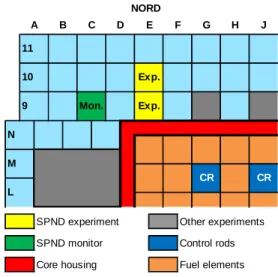
GAMMA MAJOR SPNDs were tested in four experimental locations within the core of MARIA reactor. These locations are called H-IV, H-VA, H-VB and H-VI and are presented in Fig. 4. GAMMA MAJOR SPNDs were mounted in a multi instrumented probe among different gamma detectors [15].
Measurements were performed in September 2014. Potential reactor power drift between measurements was corrected using four vanadium SPNDs installed permanently in the core.
SPND experiment Other experiments
SPND monitor Control rods
Core housing Fuel elements
NORD J 10 M CR CR Exp. Mon. Exp. A B C D E F G H N 11 9 L
ANIMMA 2015 # 186
Fig. 6. MARIA investigated core locations (in red)
3) Dedicated Monte Carlo Calculations
The international GAMMA MAJOR Project main objective was to develop a calculation scheme for the evaluation of the gamma heating at any chosen location in the MARIA reactor and to validate the existing simulation codes. Representative calculation scheme of MARIA is based on TRIPOLI4 (CEA Monte-Carlo code) used for particles transport and APOLLO2 (deterministic code) used for material balance of the MARIA reactor depleted fuel. APOLLO2 solves the transport equation in 172 energy groups and the depletion equation for the fuel and beryllium. The general development methodology of the MARIA model is step by step. It has been done by adding component after component of the reactor, and qualifying the impact of each addition by comparison with a well-known model [15].
Data obtained from the MARIA experimental measurement campaign are used to validate this calculation scheme. Its full description will be presented in a further publication in the near future. Only unperturbed calculation results were available at the time.
Thermal neutron flux levels in the four locations have also been experimentally determined using the 59Co(n,γ)60Co reaction of cobalt activation detectors for thermal flux and the
58Ni(n,p)58Co reaction on nickel for fast neutron flux.
IV. MEASUREMENTS AND RESULTS
1) Neutrons and Gamma Conditions
All experimental locations in the three research reactors have been thoroughly characterized in terms of neutron and gamma spectra and flux levels thanks to specific Monte Carlo calculations. Neutron flux levels have been validated by dosimetry measurements in each case.
Gamma flux levels are also evaluated using a recently developed process for miniature ionization chamber (MIC) signal analysis [16].
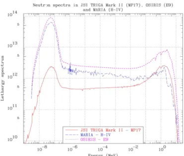
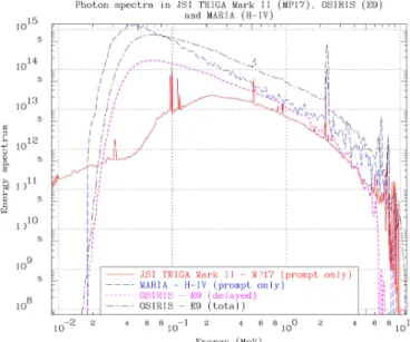
Neutrons and gamma flux values are presented in Table IV; one experimental location for each reactor. Neutron and gamma spectra in the TRIGA Mark II, OSIRIS and MARIA reactors are illustrated in Fig. 7 and 8 respectively.
Fig. 7. Neutron spectra in TRIGA, OSIRIS and MARIA experimental locations
Neutron and gamma spectra bring interesting information on the mentioned experimental locations in the TRIGA Mark II, OSIRIS and MARIA research reactors. Fig. 7 shows very different thermal (E<0,625eV) to fast (E>1MeV) flux ratios with respective values of [1,7 - 15,8 - 61,4], which extends reasons to perform nuclear instrumentation tests in various reactors and/or irradiation locations. Gamma spectra on Fig. 8 are very similar for all investigated experimental locations. The peak around 2.2MeV is due to neutron radiative capture on 16O in light water.
TABLE IV.NEUTRON AND GAMMA FLUXES IN THE TRIGA MARK II,OSIRIS
AND MARIA REACTORS
Reactor TRIGA OSIRIS MARIA
Power 250 kW 70 MW 15 MW Location MP17 E9 H-IV
φ
n,
totalcalc. 1,86.1013 2,19.1014 1,42.1014 (n.cm-2.s-1)φ
<0.625eVcalc. 5,69.1012 1,71.1014 1.21.1014 (n.cm-2.s-1)φ
>1MeVcalc. 3,40.1012 1,08.1013 1,97.1012 (n.cm-2.s-1)φ
<0.625eVAu or Co 5,27.1012 1,69.1014 1,28.1014 (n.cm-2.s-1)φ
>1MeVNi N/A 1,24.1013 2,14.1012 (n.cm-2.s-1)φ
γ,total calc. 1,95.1013 2,58.1014 1,52.1014 (γ.cm-2.s-1)φ
γ,delayed. calc. N/A 5,93.1013 N/A (γ.cm-2.s-1)Among all flux values presented in Table IV, it is very interesting to compare thermal neutron flux (φ<0.625eV) and total
gamma flux calculation results to measurements: neutron C/E ratios are very satisfactory as they vary from 0.95 to 1.08. In the TRIGA Mark II case the measurements were not conducted at the same time and with the same reactor configuration as in the SPND irradiations, which is probably the cause of the observed discrepancy. Neutron C/E ratios validate φn,total calc. values used for SPND simulations. The
comparison of total gamma fluxes (φγ,total calc. and φγ,total MIC) is
biased as calculations in TRIGA Mark II and MARIA reactors do not take into account the delayed gamma which may reach 30% [17]. At least MIC measurements have confirmed the order of magnitude of calculated total gamma flux levels. For OSIRIS reactor, the MIC signal was only workable as relative measurement due to a failure.
Fig. 8. Gamma spectra in TRIGA, OSIRIS and MARIA experimental locations
2) SPND Calculation to Experiment comparison results
Several Self-Powered Detectors have been tested in several irradiation locations in the three research reactors, giving the authors several experimental comparison points in the frame of the validation on the LDCI MATiSSe tool. In this paper, the authors concentrate on Rhodium and Cobalt emitter SPNDs, considered as standards in MTR. For MARIA reactor, only Rhodium and Silver SPNDs were available.
Table V details all measurement and calculation results for the three Rhodium SPNDs.
Electrical current C/E ratios are very satisfactory in all cases as they are all close to 1. For OSIRIS, C/E should be further improved when perturbed fluxes are available. The presence of the Rh SPND itself lowered the neutron flux [18]. In MARIA reactor, the calculated current will be improved using perturbed fluxes and a more accurate model of the GAMMA MAJOR experimental probe.
TABLE V.RHODIUM SPNDCOMPARISON IN THE TRIGA MARK II,OSIRIS AND
MARIA REACTORS
Reactor TRIGA OSIRIS MARIA
SPND Rh(a) Rh(b) Rh(c) Location MP17 E9 H-IV Imeasured 3,07.10-8 8,50.10-7 1,19.10-7 (A) Icalculated 3,11.10-8 9,57.10-7 1,15.10-7 (A) C/E 1,01 1,13 0,96 Ineutrons 97,8% 99,0% 98.5% Igamma 2,1% 1,0% 1.5%
S
n, total 3,23.10-22 7,68.10-22 8,25.10-22(A/cm . n.cm-2 .s-1 )S
n<0625eV 1,06.10-21 9,96.10-22 9,19.10-22(A/cm . n.cm-2.s-1)S
γ,total 6,61.10-24 6,59.10-24 1,17.10-23(A/cm . γ.cm-2 .s-1 )Calculated neutron and gamma contributions confirm the very low sensitivity of Rh SPNDs to photons. This statement has been previously reported by numerous references [19][20]. Neutron and gamma partial sensitivities are calculated using total and thermal neutron fluxes, total gamma fluxes and relative neutron and gamma contributions and expressed per unit length (cm) of emitter. Thermal neutron sensitivity is the most relevant for neutrons as Rh radiative capture cross section is the highest in the thermal part.
Thermal neutron and gamma sensitivity results are notably close among the three SPNDs and in good accordance with available results in the literature [19][20] [21].
All measurement and calculation results for the Cobalt and Silver SPNDs are presented in Table VI.
TABLE VI.COBALT SPNDCOMPARISON IN THE TRIGA MARK II AND OSIRIS
AND SILVER SPND IN MARIA
Reactor TRIGA OSIRIS |||| MARIA SPND Co(a) Co(b) |||| Ag Location MP17 E9 |||| H-IV Imeasured 2,31.10-9 1,05.10-7 |||| 3,97.10-7 (A) Icalculated 3,13.10-9 1,03.10-7 |||| 4,52.10-7 (A) C/E 1,35 0,98 | 1,14 Ineutrons 89,3% 97,3% |||| 96.8% Igamma 10,7% 2,7% |||| 3.2%
S
n, total 2,22.10-23 9,33.10-23 |||| 3,18.10-22 (A/cm . n.cm-2.s-1)S
n<0.625eV 7,25.10-23 1,21.10-22 |||| 3,55.10-22 (A/cm . n.cm-2 .s-1 )S
γ,total 2,54.10-24 2,20.10-24 |||| 9,83.10-24 (A/cm . γ.cm-2 .s-1 )Electrical current C/E ratios for Co SPNDs are satisfactory as they are all relatively close to 1 but the Co SPND current calculation needs to be improved as in TRIGA the current is overestimated (authors are also doubtful about the SPND reliability during this measurement) and in OSIRIS, perturbed fluxes should lead to current underestimation. In MARIA reactor, the calculated Ag SPND current improve using perturbed fluxes and a more accurate model of the GAMMA MAJOR experimental probe.
ANIMMA 2015 # 186 Co SPND gamma sensitivity is, in these experiments,
relatively low but it has been reported in other publications to be either positive or negative. It is strongly dependent on the immediate environment of the detector. The used Ag SPND is also predominantly sensitive to neutrons.
Thermal neutron sensitivities are also the most relevant for Co and Ag SPNDs Thermal neutron sensitivity results are in good accordance with available results in the literature [20][21].
V. CONCLUSION -DISCUSSION
The LDCI collaborations with three research facilities offered a unique opportunity to test a large variety of neutron and gamma detectors in different research reactors environments with a wide range of thermal to fast neutron ratios and gamma flux levels.
Full characterization of neutron and gamma flux spectra and levels in irradiation locations in the reactors with dedicated Monte Carlo calculations, dosimetry and ionization chamber measurements is also unique and can be considered as reference experiments for calculation to experiment comparisons.
SPND C/E ratios presented in this paper are very promising in the frame of the validation of the LDCI MATiSSe tool for SPND simulation. The full analysis of the VASCO experiment performed in the OSIRIS reactor with various Self-Powered Detectors will be reported in the near future and will also provide more comparison points to consolidate the SPND simulation tool.
All effort made by the different units involved in the experimental campaigns will help the LDCI MATiSSe numerical tool to be ready for nuclear instrumentation definition of irradiation experiments in the future Jules Horowitz Reactor (JHR).
ACKNOWLEDGMENT
Authors are grateful to the operators of the TRIGA Mark II and MARIA reactors for preparation of the experiments and running the reactor at the most achievable stable power.
Authors also want to especially thank Valérie Lepeltier and Jacques Bubbendorf from CEA SIREN, for their assistance before, during and after the OSIRIS experiment.
This work was performed with funding from the Nuclear Instrumentation Project of the CEA Nuclear Energy Division. The work performed at the JSI TRIGA reactor was supported by the Slovenian Research agency and carried out within the framework of the bilateral CEA / Ministry of higher education, science and technology of Slovenia project no. BI-FR/CEA/10-12-005, contract no. 1000-10-340005. The work at the MARIA reactor was supported by Ministry of Science and Higher Education Republic of Poland (13PPLA000012), CEA Reactor Study Department, National Centre for Nuclear Research (Poland) and Aix-Marseille University (France).
REFERENCES
[1] L. Vermeeren, R. Van Nieuwenhove‚ ‘Theoretical study of radiation induced electromotive force effects on mineral insulated cables’, American Institute of Physics, Review of Scientific Instruments volume 74 - number 11, 2003.
[2] L. Vermeeren, ‘Absolute on-line in-pile measurement of neutron fluxes using self-powered neutron detectors : Monte-Carlo sensitivity calculations’, European Nuclear Society, Berne (Switzerland) ENS RRFM 2001, Transactions, Oral presentations and posters, p.p. 61-65, 2001.
[3] R. Van Nieuwenhove, L. Vermeeren, ‘Online gamma dose-rate measurements by means of a self-powered gamma detector’, IEEE Trans. Nucl. Sci., vol. 49, n° 4, pp 1914-1918, 2002.
[4] G.F. Lynch, ‘Some theoretical aspects of self-powered detectors’, Atomic Energy of Canada Limited, Rapport AECL-5124 paper 1.8, 1974.
[5] C. Blandin, ‘Contribution au développement de collectrons pour la mesure instantanée et sélective des différents champs de rayonnements en réacteurs nucléaires’, Thèse de l’Institut National Polytechnique de Grenoble, France, 1998.
[6] X-5 Monte Carlo Team, MCNP6 User’s Manual, Version 1.0, May 2013, LA-CP-13-00634.
[7] JANIS4.0 web nuclear data library available at http://www.oecd-nea.org/janis/
[8] M. Ravnik, R. Jeraj, ”Research reactor benchmarks,” Nucl. Sci. Eng. 145(2003)145-152.
[9] L. Snoj et al., Analysis of neutron flux distribution for the validation of computational methods for the optimization of research reactor utilization, Appl. Radiat. Isot. 69, 136-141.
[10] V. Radulović et al., Validation of absolute axial neutron flux distribution calculations with MCNP with 197Au(n,γ)198Au reaction rate distribution
measurements at the JSI TRIGA Mark II reactor, App. Rad. Isot. 84, 2014, 57-65.
[11] TRIPOLI-4 Monte Carlo Transport Code, http://www.nea.fr/abs/html/nea-1716.html (2013).
[12] F. Malouch , F. Lopez, L. Barbot, D. Fourmentel, ‘Calculation of neutron and gamma fluxes in support to the interpretation of measuring devices irradiated in the core periphery of the OSIRIS Material Testing Reactor’, 4th International Conference ANIMMA 2015, 20-24 April
2015, Lisbon, Portugal.
[13] M. Migdal, T.Krok, ‘Brief history of MARIA conversion from HEU to LEU’, 35th International Meeting RERTR 2014, 12-16 October 2014,
Vienna, Austria.
[14] K.Pytel, et al., MARIA Reactor Safety Analysis Report, National Centre for Nuclear Research, Poland, 2015.
[15] M. Tarchalski et al., ‘Development and experimental qualification of a calculation scheme for the evaluation of gamma heating in experimental reactors. Application to Jules Horowitz (JHR) and to the MARIA reactors’, 4th International Conference ANIMMA 2015, 20-24 April 2015, Lisbon, Portugal
[16] D. Fourmentel et al., ‘Delayed Gamma Measurements in Different Nuclear Research Reactors Bringing Out the Importance of the Delayed Contribution in Gamma Flux Calculations’, 4th International Conference
ANIMMA 2015, 20-24 April 2015, Lisbon, Portugal.
[17] V. Radulović, et al., ‘Measurements of miniature ionization chamber currents in the JSI TRIGA Mark II reactor demonstrate the importance of the delayed contribution to the photon field in nuclear reactors’, paper submitted in April 2015 to Nuclear Instruments and Methods in Physics Research Section A.
[18] V. Radulović, et al., ‘Multi-step Monte Carlo calculations applied to nuclear reactor instrumentation - source definition and renormalization to physical values’, 4th International Conference ANIMMA 2015, 20-24
April 2015, Lisbon, Portugal.
[19] H.D. Warren, ‘Calculational model for self-powered neutron detector’, Nuclear Science and Engineering, Vol. 48, pp. 331-342, 1972.
[20] L. Vermeeren et al., ‘Irradiation tests of prototype self-powered gamma and neutron detectors’, 2nd ANIMMA international conference
publication DOI 10.1109/ANIMMA.2011.6172889.
[21] M. Agu, H. Petitcolas, ‘Self-powered detector response to thermal and epithermal neutron flux’, Nuclear Science and Engineering, Vol. 107, Issue 4, pp. 374-384, 1991.