Constitutive Modeling of Advanced Thermoset Composites
with Application to Sheet Forming Processes
by
Jamie N. Kofoid
B.S., University of California, Berkeley (2001)
Submitted to the Department of Mechanical Engineering in partial fulfillment of the requirements for the degree of
MASTER OF SCIENCE IN MECHANICAL ENGINEERING
at the
MASSACHUSETTS INSTITUTE OF TECHNOLOGY
June 2004
@
Massachusetts Institute of TechnologyMASSACHUSETS INS E
OF TECHNOLOGY
JUL 2 0 2004
LIBRARIES
The author hereby grants to MASSACHUSETTS INSTITUTE OF TECHNOLOGY permission to reproduce and
to distribute copies of this thesis document in whole or in part.
Signature of Author...
C ertified by ...
Dep/rtme t / viechanical Engineering
A
7 May 2004Simona Socrate Assistant Professor of Mechanical Engineering Thesis Supervisor
A ccep ted by ...
Ain A. Sonin Chairperson, Department Graduate Committee
M ITLbraries
Document Services
Room 14-0551 77 Massachusetts Avenue Cambridge, MA 02139 Ph: 617.253.2800 Email: [email protected] http://Iibraries.mit.edu/docsDISCLAIMER OF QUALITY
Due to the
condition of the original material, there are unavoidable
flaws in this reproduction.
We
have made
every
effort possible
to
provide you with the best copy available. If you are dissatisfied with
this product and find it unusable, please contact Document Services as
soon as possible.
Thank you.
The images contained in this document are of
the best quality available.
Constitutive Modeling of Advanced Thermoset Composites with Application to Sheet Forming Processes
by
Jamie N. Kofoid
Submitted to the Department of Mechanical Engineering
on 7 May 2004, in partial fulfillment of the
requirements for the degree of
MASTER OF SCIENCE IN MECHANICAL ENGINEERING
Abstract
Advanced thermoset composites are an important class of materials employed primarily in aerospace applications that consist of a thermoset polymer resin matrix that is reinforced by systematically arranged, continuous graphite fibers. Composite sheet forming, or thermoform-ing, is a process where flat sheets of composite layups are heated and formed into desired part shapes. Due to the complex nature of composite material response, successful composite sheet forming processes (that avoid defects such as fiber wrinkling) are traditionally the result of costly trial-and-error methods.
The main objective of this research is to develop constitutive material models that can be utilized for modeling thermoset composite response during sheet forming processes. A contin-uum model has been developed that accounts for temperature and rate dependencies and allows solid finite element modeling that tracks material response on the microscopic level, including fiber wrinkling. The second model is a simplified, transversely isotropic elastic-plastic model that can be used together with a finite element model which employs structural (shell) elements to monitor macroscopic material response in a less computationally-intensive manner.
The constitutive parameters of both models were optimized to match observed material behavior from unidirectional tensile and bending tests conducted on the composite at various temperatures and strain rates. The models were tested against a series of three-point bending verification tests that were conducted on quasi-isotropic composite layups at various rates and temperatures. Also included is an investigation of various finite element approaches that can be employed using these models to simulate forming processes.
The completed continuum model satisfactorily captures most composite behavior, with the exception of transverse shear flow behavior along the fibers. The model, developed using the assumption of isotropic flow response, requires greater refinement in order to more accurately capture composite behavior. The completed transversely isotropic elastic-plastic model sat-isfactorily captures all modes of composite behavior observed during experimentation. The simplified nature of this model, however, limits it from accurately describing behaviors such as fiber wrinkling during deformation.
Thesis Supervisor: Simona Socrate
Contents
1 INTRODUCTION
1.1 Preimpregnated Composites ...
1.2 Forming Processes ...
1.3 Composite Deformation Behavior...
1.4 Motivation and Research Objectives . . .
1.5 Thesis Overview ...
2 UNIDIRECTIONAL (UD) COMPOSITE REVIEW 2.1 Introduction . . . . 2.2 Kinematic Models . . . . 2.3 Constitutive Models . . . . 2.3.1 Continuum Models ... 16 16 17 19 20 22
SHEET FORMING LITERATURE
2.3.2 Layer Slip Models ...
2.4 Computer Implementations of Constitutive Models
3 MATERIAL BEHAVIOR AND DISCUSSION 3.1 General Observations ...
3.2 Material Behavior Isolation: Tensile and Bending
3.2.1 Introduction ... 3.3 Transverse Test Results ...
3.3.1 Observations ... Tests 3.3.2 Temperature Dependence . . 25 25 26 28 28 31 32 34 34 36 36 39 39 44
3.3.3 Rate Dependence . . . .
3.4 Axial Test Results . . . .
3.4.1 Observations . . . .
3.4.2 Temperature Dependence . . . .
3.4.3 Rate Dependence . . . .
3.4.4 Axial Test Results Summary . . . .
3.5 Unidirectional Layup Bending Results . . .
4 CONSTITUTIVE MATERIAL MODELING
4.1 Constitutive Modeling Introduction . . . .
4.2 Solid Continuum Model . . . .
4.2.1 Resin Test Summary and Constitutive
4.2.2 Continuum Mechanics Introduction. .
4.2.3 Constitutive Model Development . . .
4.3 Transversely Isotropic Elastic-Plastic Model .
4.3.1 Orthotropic Elasticity . . . .
4.3.2 Anisotropic Plasticity . . . .
4.3.3 Approximate Model Summary and Req
44 . . . . 4 6 . . . 4 6 . . . 4 8 . . . 4 8 . . . 4 8 . . . 4 9 60 . . . 60 . . . 61 Modeling Suggestions . . . 61 . . . 61 . . . 66 . . . 75 . . . 77 . . . 80 uired Variables . . . 84
5 FINITE ELEMENT MODELING APPROACHES FOR SHEET FORMING PROCESSES 86 5.1 Introduction . . . 86
5.2 Fiber Wrinkling During Composite Sheet Forming . . . 87
5.3 Representative Geometry for Testing Buckling Behavior . . . 87
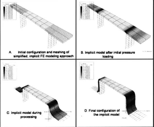
5.4 Implicit Versus Explicit Finite Element Approaches . . . 89
5.4.1 Introduction . . . 89
5.4.2 Implicit modeling of sample process . . . 91
5.4.3 Explicit modeling of sample process . . . 91
5.4.4 D iscussion . . . 95
5.5 Continuum Versus Shell Elements . . . 95
5.5.2 Shell element model of sample process . . . .
5.5.3 Comparison of shell and continuum explicit finite element models .
5.6 Shell-Continuum Element Submodeling . . . .
5.6.1 D escription . . . .
5.6.2 Shell-continuum element submodel of sample process . . . .
5.7 Recommendations for Modeling Sheet Forming Processes . . . .
5.8 Sample Implementation of the Continuum Constitutive Material Model .
6 CONSTITUTIVE MODEL PARAMETER FITTING
6.1 Continuum Parameter Fitting ...
6.1.1 Introduction ... ... 6.1.2 Axial/Fiber Tests ...
6.1.3 Transverse/Resin Tests . . . .
6.1.4 Completed Continuum Model . . . .
6.2 Transversely Isotropic Elastic-Plastic Model Fitting . . .
6.2.1 Axial Elastic Parameter Fitting . . . .
6.2.2 Plastic Parameter Fitting . . . .
6.2.3 Shear Parameter Fitting . . . .
6.2.4 Completed Approximate Model . . . .
6.3 Comparison of Constitutive Models . . . .
7 THREE-POINT BENDING SIMULATIONS OF
QUASI-POSITE LAYUPS
7.1 Experimental Setup ...
7.2 Quasi-Isotropic Experimental Results ...
7.2.1 Quasi-Isotropic versus Unidirectional Test Results
7.2.2 Temperature Dependence in Quasi-Isotropic Tests
7.2.3 Rate Dependence in Quasi-Isotropic Tests . . . .
7.3 Continuum Model Predictions . . . .
7.3.1 Introduction . . . . 7.3.2 Continuum Model Results . . . .
105 . . . 1 0 5 . . . 1 0 5 . . . 106 . . . 1 0 7 . . . 1 1 5 . . . 1 1 9 . . . 1 1 9 . . . 122 . . . 124 . . . 132 . . . 1 3 5 ISOTROPIC COM-137 . . . 137 . . . 141 . . . 141 . . . 143 . . . 144 . . . 146 . . . 146 . . . 146 . . . . 96 . . . . 98 . . . . 99 . . . . 99 . . . . 99 . . . . 99 . . . . 101
7.4 Approximate Model Predictions . . . 152
8 CONCLUDING REMARKS 158
8.1 Conclusions . . . 158
8.2 Recommended Future Work for Constitutive Model Development ... 159
List of Figures
1-1 Single lamina of the composite test material: (A) photograph of lamina and (B)
schematic description of photograph. . . . . 17
1-2 Schematic representation of a simple sheet forming process. . . . . 18
1-3 Deformation Modes in Composite Sheet Forming . . . 20
1-4 Photograph illustrating fiber wrinkling in a formed composite part. The length scale of this part is several meters long, with a thickness of approximately 5 mm, and fiber wrinkling on the order of 0.5 mm. . . . 21
3-1 Summary of material specifications provided by the manufacturer for a similar
prepreg com posite. . . . 36
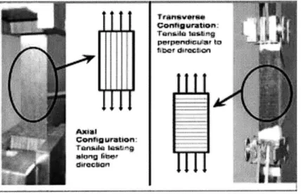
3-2 Photographs and schematics for (LEFT) Axial testing meant to isolate carbon
fiber behavior and (RIGHT) Transerve testing meant to isolate the thermosetting resin behavior . . . 38
3-3 Photograph and schematic representation of the unidirectional three-point
bend-ing experim ent. . . . 38 3-4 Summary of all temperature and strain rates for transverse testing. . . . 40
3-5 First samples photos of transverse configuration before (LEFT) and after (RIGHT)
tensile testing testing. . . . 41
3-6 Second sample photos of transverse configuration before (LEFT) and after (RIGHT)
tensile testing testing. . . . 42
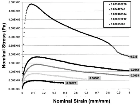
3-8 Typical resin test nominal stress-strain plot, consisting of two distinct regions. Region A represents an initial loading behavior dominated by elastic resin be-havior. Region B is dominated by the viscous resin behavior after a critical stress value has been surpassed. . . . 43
3-9 True stress-strain plot of the data presented in Figure 3-8. . . . 43
3-10 Comparison of observed resin stress-strain behavior with that of idealized
vis-coelastic behavior. . . . 45
3-11 Plots of four resin tests at one strain rate, but variable temperatures . . . 45 3-12 Close-up view of elastic resin behavior from the previous figure. Also shown are
the approximate, ideal elastic behaviors up to yielding for 35 and 40 degree trials. 51
3-13 Plots of four resin tests at room temperature, but variable strain rates. . . . 51
3-14 Summary of all temperature and strain rates for axial testing. . . . 52
3-15 Experimental plots from axial testing at a strain rate of 0.006/s and various
tem peratures. . . . 52
3-16 Photographs of fiber testing experiment: (A) before and (B) after fiber failure. . 53
3-17 Photographs of fiber test specimens: (Left) Sample material before tensile
test-ing, (Middle) Room temperature specimen after testtest-ing, and (Right) Several specimens from elevated temperature testing. . . . 53
3-18 Schematic representation of cross-sectional area fraction of fibers and matrix.
The fibers are represented as black in the figure, and surrounding matrix is white. 54
3-19 Plots of fiber test results at a fixed strain rate and various temperatures. . . . 54 3-20 Zoomed-in view of previous figure, illustrating consistency of elastic stress-strain
slope at all tem peratures. . . . 55
3-21 Plots of representative room temperature fiber test results, with various strain rates... ... 55 3-22 Zoomed-in view of previous figure, illustrating consistency of elastic stress-strain
slope at all strain rates. . . . 56
3-23 Summary of all calculated elastic moduli from fiber test trials. . . . 56
3-24 Representative plots of the elastic regime for all combinations of temperature and strain rates. . . . 57
3-25 Comparison between the manufacturer's specifications and experimentally
de-rived, effective fiber modulus and yield stress . . . 57
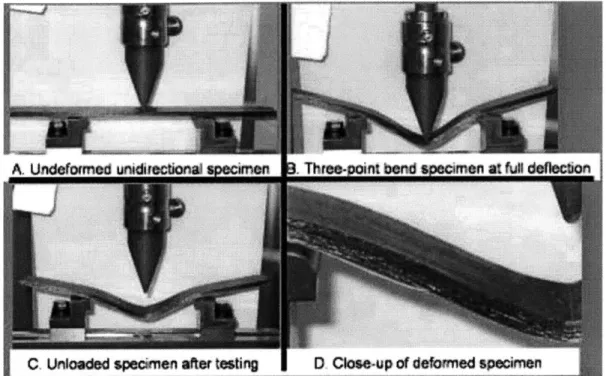
3-26 Photographs illustrating the three-point bending of a unidirectionally oriented com posite specim en. . . . .
58
3-27 Force-deflection results of unidirectional specimen three-point bending at three test temperatures. ... ... ... .58
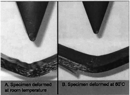
3-28 Photographs illustrating the ability of the composite to more evenly deform at elevated tem peratures. . . . 59
4-1 Kinematical description of deformation gradient . . . 62
4-2 Kinematical description of elastic-plastic decompositon . . . 63
4-3 Schematic description of continuum constitutive model. . . . 67
4-4 Schematic representation of the constitutive model . . . 68
4-5 Summary of variables defining material behavior in the constitutive model. . . . 76
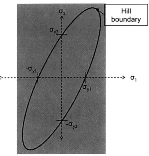
4-6 Schematic description of the three principal directions on the composite material. 76 4-7 Schematic, 2-D representation of the von Mises yield criteria. Yielding occurs outside the boundary, while behavior inside the boundary remains completely elastic. . . . 81
4-8 Schematic, two-dimensional representation of the Hill anisotropic yield criteria. . 83 4-9 Summary of all required material constants for the approximated model. . . . 85
5-1 Photograph of fiber buckling associated with failed sheet forming processes (cour-tesy of Boeing). . . . 87
5-2 Isometric views of sample part geometry, including: (A) the forming tool geom-etry alone and (B) the forming tool with heater plates that facilitate forming. . . 88
5-3 Top-view of sample part geometry, including inner and outer radii of curvature. . 89 5-4 Step-by-step depiction of sample sheet forming process. The deformation from steps (A)-(D) is driven by pressure applied to the top of the sheet and the downward travel of the heated plates. . . . 90
5-5 Step-by-step depiction of implicit implemenation of forming process. The asso-ciated material model is linear-elastic. . . . 92
5-6 Detail of the forming of the outer flange using an explicit FE approach. The
associated material is isotropic, linear-elastic. . . . 93
5-7 Plots of energies associated with the explicit model and the forming process.
These energies are as follows: AE is Artificial Energy, IE is Internal Energy, KE is Kinetic Energy, and SE is Strain Energy. . . . 94
5-8 Deformed configurations of the solid (left) and shell (right) element pull tests. . . 96
5-9 Comparative energy-time plots of each pull-test model. The plotted quantities
are Artificial Energy (AE), Kinetic Energy (KE), and Strain Energy (SE). . . . . 97
5-10 Results of the sample forming process using shell elements and an explicit FE
algorithm. The contour levels correspond to the bottom plane of the wedge. . . . 98
5-11 Contour plot results of the shell model and a solid submodel of its outer flange. .100 5-12 Plots illustrating the layup structure of estimated continuum composite model.
(A) Contour plot of the wedge configuration, where the plotted variable is the
x-component of the unit fiber vector, (B) Close-up of the contour plot, and (C) Schematic representation of the 16-layer composite. . . . 102
5-13 Mises contour plots of the inner flange of the 16-ply composite model. . . . 103
5-14 Detailed view illustrating ply-slippage in the outer flange during the forming process. . . . 104
5-15 Detailed view of the outer flange, including meshing, that indicates fiber buckling
has arisen during forming. . . . 104
6-1 Table summarizing the calculated elastic parameters at various test temperatures. 108
6-2 Plot of temperature versus calculated elastic moduli for the resin. The nature of
temperature dependence has been fit via an exponential model for the range of tem peratures of interest. . . . 109
6-3 Log-log plot of all resin testing data and the linear fits of isothermal material
behavior. . . . 111 6-4 Summary of linear fit lines shown in preceeding Figure. . . . 112
6-5 Log-log plot of all resin testing data and the corrected linear fits at constant
6-6 Summary of the values for parameter A and the associated temperatures with
each value. . . . 114
6-7 Plot of 1 versus A along with a linear fit of the data points. . . . 114
6-8 Summary of continuum material parameters and their calculated values. . . . 116
6-9 Plot of computer simulation results of axial testing model with Ef Af = 108.6GPa.
116
6-10 Comparitive plots of model versus measured stress-strain behavior at 40 C and
five different strain rates. . . . 117
6-11 Comparitive plots of model versus measured stress-strain behavior at a 0.74/s
strain rate and four different temperatures. . . . 117
6-12 Comparitive plots of model versus measured stress-strain behavior at a 0.37/s
strain rate and four different temperatures. . . . 118
6-13 Comparitive plots of model versus measured stress-strain behavior at a 0.002/s
strain rate and three different temperatures. . . . 118 6-14 Plots of axial test data (in gray), along with an estimated elastic modulus line
of 108.6 GPa. This estimate is applied to parameters in the approximate model at all temperatures and strain rates. . . . 120
6-15 Plots of transverse test data (in gray) at 50 'C, along with an estimated elastic
modulus of 1.65 MPa. This estimate is applied to parameters in the approximate model at 50 'C and 0.37/ s nominal strain rate. . . . 121
6-16 Plots of axial test data (in gray), along with an estimated "yield" stress line
equal to 1.0 GPa. This estimate is applied to parameters in the approximate model at all temperatures and strain rates. . . . 123
6-17 Plots of transverse test data (in gray) at 323 K, along with an estimated "yield"
stress of 66.5 kPa. This estimate is applied to the approximate model at 323 K and 0.37/ s nominal strain rate. . . . 123
6-18 Two views of the parts and geometry in the three-dimensional three-point
bend-ing finite element model. The modeled specimen is 25.4mm wide, 4.36mm thick, and spans 100mm between supports. . . . 125
6-19 TOP: Front-view photograph of three-point bending apparatus, including a 20-ply unidirectional composite specimen. BOTTOM: Same view of the finite
ele-ment model. Both images show a support-to-support separation of 100mm and specimen thickness of 4.36mm. . . . 126
6-20 LEFT: Close-up of the three-point bending apparatus. RIGHT: Same view of
the finite element model. . . . 126
6-21 Two views of the finite element model with the applied assumptions of symmetry
and plane strain behavior. LEFT: Isometric view. RIGHT: Cross-sectional view including the meshed composite specimen. . . . 127
6-22 Boundary conditions applied in the three-point bending finite element simulation.
The specimen dimensions are now 0.254mm wide, 4.46mm thick, and 50mm support-to-midplane separation. . . . 128
6-23 Plots showing experimental force-displacement bending behavior at 40 C and 60 0C, as well as the elastic behavior of the approximate model using estimated
shear moduli at 50'C and 60'C. . . . 129
6-24 Plots showing experimental force-displacement bending behavior at 40 0C and
60 0C, as well as the finite element model results approximating behavior at
500C and 60 . . . . 130
6-25 Contour plots comparing strain values during three-point bending. The two
tensile contours reflect zero plastic straining, while shear plastic straining reaches maximum values of 0.077 due to bending. . . . 131
6-26 LEFT: Deformed part shape from the modeling of three-point bending at 60 0C.
RIGHT: Photograph of deformed composite after bending at 60'C . . . 131
6-27 Plot comparing axial test data with the performance of the approximate
consti-tutive m odel. . . . 132
6-28 Comparative stress-strain plots of experimental transverse test data with the
behavior of the approximate model at 50 C and two strain rates. . . . 133
6-29 Comparative stress-strain plots between the approximate model and
experi-mental test data under conditions approximately equal to that sheet forming
6-30 Comparative stress-strain plots of constitutive models at a variety of strain rates
and at a temperature of 323K. . . . 135
6-31 Comparison of constitutive models at the approximately correct temperature and
strain rate of actual sheet forming processes. . . . 136
7-1 Photograph of three-point bending test apparatus, as well as a schematic
detail-ing some apparatus dimensions. . . . 138
7-2 Schematic diagram of the three-point bend apparatus, including the coordinate
system used to described the composite layups. . . . 139
7-3 Schematic representation of the composite layups employed during the
verifica-tion testing phase. . . . 139 7-4 Summary of three-point bend experiments performed, including displacement
rates and test temperatures. . . . 141
7-5 Plots comparing three-point bending force-displacement behavior of quasi-isotropic
and unidirectional specimens at 24 . . . 141
7-6 Plots comparing three-point bending force-displacement behavior of quasi-isotropic
and unidirectional specimens at 40 . . . 142
7-7 Plots comparing three-point bending force-displacement behavior of quasi-isotropic
and unidirectional specimens at 60 . . . 142
7-8 Photographs of three-point bend composite specimens after loading and
unload-ing at various temperatures. . . . 143
7-9 Representative force-displacement plots at the midpoint of three-point bend
spec-imens at a 12.7 mm/min loading rate and various test temperatures. . . . 145
7-10 Representative force-displacement plots at the midpoint of three-point bend
spec-imens at a 127 mm/min loading rate and various test temperatures. . . . 145
7-11 Photographs showing two three-point specimens deformed unter the following
conditions: (TOP) room temperature and 1.27mm/min displacement, and
(BOT-TOM) room temperature and 12.7 mm/min. . . . 147
7-12 Representative force-displacement plots at the midpoint of three-point bend
spec-imens at a room temperature (24 C) and loading rates of 1.27 mm/min, 12.7 mm/min, and 127 mm/min. . . . 147
7-13 Representative force-displacement plots at the midpoint of three-point bend
spec-imens at a 40 C and loading rates of 1.27 mm/min, 12.7 mm/min, and 127 m m /m in. . . . 148 7-14 Representative force-displacement plots at the midpoint of three-point bend
spec-imens at a 60 C and loading rates of 1.27 mm/min, 12.7 mm/min, and 127 m m /m in. . . . 148
7-15 For the quasi-isotropic, elastic-plastic transversely isotropic finite element model,
the unidirectional specimen is (A) partitioned and (B) the appropriate material
orientations are applied at each layer through the thickness. . . . 149
7-16 The continuum model utilizes state variables to define fiber orientations of the
quasi-isotropic layup. . . . 150
7-17 Matrix of verification tests conducted with the continuum constitutive model. . .150 7-18 Mises contour plots depicting the deformation of the continuum quasi-isotropic
model up until 5.5mm of midpoint deflection. . . . 151
7-19 Force-displacement response of the continuum model versus experimental data
at 40 C and a 12.7 mm/min displacement rate. . . . 152
7-20 Force-displacement response of the continuum model versus experimental data
at 24 C and a 12.7 mm/min displacement rate. . . . 153
7-21 Force-displacement response of the continuum model versus experimental data
at 40 C and a 127 mm/min displacement rate. . . . 153
7-22 Contour plots illustrating the elevated levels of shear strain versus tensile strain
in the composite at large deformations. . . . 154
7-23 Images depicting quasi-isotropic approximate model bending behavior. . . . 155
7-24 Plastic strain contour plots during the bending of a quasi-isotropic approximate m odel specim en. . . . 155
7-25 Comparison of (LEFT) a deformed quasi-isotropic specimen with (RIGHT) the
deformed shape of a quasi-isotropic, approximate model representation of the specim en. . . . 156
7-26 Closer investigation of approximate model behavior versus experimental data for
8-1 Three deformation modes available within composite sheets during processing. This figure was first given in Chapter 2. . . . 160
8-2 Two views of the simplified tool geometry used to test the accuracy of the
con-stitutive m odels. . . . 162
8-3 View examining the tool's secondary curvature, as well as its overall length and
width. . . . .. . ... .. . .... ... . .. . . . 162
8-4 View describing the sheet geometry that is formed onto the tools. . . . 163
8-5 Three views representing the orientation of sheet and die before forming takes
Chapter 1
INTRODUCTION
1.1
Preimpregnated Composites
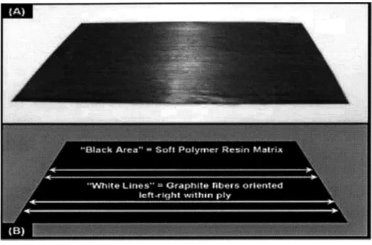
Fiber-reinforced composites are a successful class of materials that consist of lightweight, rela-tively weak matrix material(s) reinforced by stiff, usually systematically arranged, reinforcement fibers. Long-fiber composites are strong along their fiber directions while maintaining a rela-tively light overall weight. Among the most common composite materials used in aerospace applications are preimpregnated (prepreg) sheets of continuous, unidirectionally aligned (UD) graphite reinforcement fibers within either a thermoplastic or thermoset polymer matrix. Fig-ure 1-1 includes a photograph and schematic description of one such thermosetting prepreg ply, or lamina, manufactured by the Toray Corporation for aerospace applications. As visible in the figure, the matrix material accounts for a high percentage of the prepreg's volume. The many individual fibers, arranged linearly within the matrix (left-to-right in the photograph), are also noticeable as a "grain" pattern in the prepreg. Individual prepregs, such as the one in the figure, are quite thin (approximately t - 0.21 mm), flexible, with a slightly tacky matrix at room temperature. It is this tackiness that allows parts to be formed by stacking multiple layers (laminae) of prepregs into "lay-ups" of the desired shape and thickness. Each composite lamina within the formed part is oriented with fibers aligned along directions of desired material strength, with most lay-ups maximizing overall strength by having prepregs oriented in several different directions.
Figure 1-1: Single lamina of the composite test material: (A) photograph of lamina and (B) schematic description of photograph.
1.2
Forming Processes
Creating composite parts by manually stacking prepreg layers is called the "hand lay-up" process. Hand lay-up of composite parts, however, is expensive, slow, and can lead to personal injury for the numerous workers required to carefully stack and press hundreds or thousands of layers of prepreg sheets into one part. Companies have increasingly searched for more cost-effective and socially acceptable alternatives to hand lay-up, such as sheet forming (also called composite thermoforming), that automate processes, reduce costs, and greatly decrease the time required to create composite parts.
Sheet forming is the process of converting thin, flat sheets of material into useful parts with complicated, curvilinear shapes. Sheet metal forming has long been employed in areas such as the automotive industry, and composite sheet forming has been increasingly employed by the aerospace industry during the past 20 years. Sheet forming processes, in principle, are the same for all materials, as illustrated schematically in Figure 1-2. This example is one of the most common forms of sheet forming, with a sheet (typically metal) being subjected to
U *11 m. *m -
-pressure and forced onto a die until it deforms into a desired part shape. The one primary difference between the two processes of metal forming and polymer-matrix composite sheet forming, also called composite thermoforming, is that composite sheets are typically heated to above the polymer's melt temperature before forming. The melted polymer matrix also acts as a "lubricant", facilitating deformation of reinforcing fibers and decreasing the likelihood of buckling or wrinkling. Flat, S he e _ M ate rial - ,.Sheet -brought in to con ta ct w ith die
B. Sheet is pressed into die by tooling or
A. Sheet Forming Components applied pressures
Sheet
form ed into Final, formed part
die
C. Sheet is formed, and retains shape of the die once it has been removed.
Figure 1-2: Schematic representation of a simple sheet forming process.
Perhaps the most important industrial difference between these two types of processes is that sheet metal behavior during forming can be well described and modeled according to plastic flow theory[8], while composite sheet forming has historically suffered from a lack of ability to predict part formability and material behavior during forming. This difference implies that, while metal part formability can be tested and verified via inexpensive tools such as computer modeling, part formability for composite materials is much harder to predict. In addition to factors such as part geometry, processing conditions, and forming interactions, composite part formability is also dependent upon the complex material behavior and interaction of the composite's fibers and matrix. Poorly designed composite forming processes typically result in fiber defects, arising from buckling or wrinkling, or uneven matrix distribution within the
part. The design of successful forming procedures has traditionally involved costly trial-and-error methods requiring many iterations before an optimal solution can be determined. The development of proper analysis and modeling techniques, similar to those used in sheet metal forming, is vital for minimizing the costs associated with designing and manufacturing advanced composite parts through thermoforming.
1.3
Composite Deformation Behavior
One of the keys to successful composite sheet forming is the flowing nature of the resin matrix at the elevated temperatures of thermoforming. The melted resin facilitates fiber movement without twisting or buckling, as well as easier conformance of parts to tooling. While thermo-plastic and thermoset resins are quite different chemically, both flow similarly at their respective thermoforming temperatures. Thermoset resins require lower temperatures to begin forming, are generally less viscous than thermoplastics, and can be formed at lower costs. However, crosslinking reactions prevent reshaping of thermoset parts after curing. Thermoplastics, on the other hand, can be reheated and formed numerous times. The composites characterized in this thesis are thermosets, but thermoplastic matrices at forming temperatures can be mod-eled through similar approaches and the research presented in this document is therefore also relevant for these materials.
Proper forming, without wrinkling or buckling, of UD composite parts is dependent upon three available deformation modes: transverse fiber flow, intraply shearing, and inter-ply slippage [32]. Transverse fiber flow, or "squeezing" flow, is the outward migration of parallel fibers when ex-posed to a normal pressure (Figure 1-3A). Intraply shearing in a UD composite may occur along two planes (Figure 1-3B) and is characterized as the parallel movement of fibers in rela-tion to one another. Inter-ply slip is the mechanism of sliding between prepreg sheets during the formation of parts with non-zero curvature (Figure 1-3C). It has been found that resin-rich, lubricating layers form between prepreg sheets that facilitate inter-ply slippage during forming. Another vital parameter affecting forming conditions for composite parts is friction between part and tooling. Excessive friction can ruin parts by causing wrinkling or even tearing of the outer prepreg plies in contact with tooling. Improvement upon existing trial-and-error
de-A: "Squeezing" Flow, perpendicular to fibers, leading to fiber migration
B: Intra-Ply Shearing, characterized by parallel fiber movement within a composite sheet
C: Inter-Ply Shearing, characterized by movement between adjacent composite sheets
Figure 1-3: Deformation Modes in Composite Sheet Forming
sign methods requires proper understanding (and modeling) of material behavior, deformation mechanisms, and factors such as friction. For more comprehensive introductions to composites, their material behaviors, and forming processes, refer to Astrom[2], Gutowski[20], or Advani[1].
1.4
Motivation and Research Objectives
Accurate modeling of composite sheet forming can lead to faster and less expensive identification of optimal forming conditions for composite parts. Various modeling techniques, with varying degrees of success, have been developed over the past 20 years for the prediction of composite part formability. These models have addressed several concerns, such as the movement of fibers during forming, the locations of fiber wrinkling and buckling, characteristics of resin flow, or defects associated with certain part geometries. The objective of this research is to develop a constitutive material model for thermoset composites that accounts for the actual material behavior of the polymer matrix and carbon fibers. Once properly implemented, the material model is to be used for finite element modeling of sheet forming processes being developed and
utilized by the Boeing Company for its commercial airliners. The constitutive model is meant to describe forming behavior for an existing process, as well as serve as a tool for predicting new composite part forming procedures.
One of the greatest difficulties associated with this modeling development is the orders of magnitude differences between the size of the parts being modeled and the defects that arise during processing. A representative composite sheet, for example, has dimensions of 1 meter wide by 20 meters long by 5 millimeters thick. Defects arising in this part during formation, such as fiber wrinkling, will only occur through the sheet's thickness dimension. Figure 1-4 provides a cross-sectional photograph of one such formed composite part with fiber wrinkling through its thickness. As illustrated, the length scale of wrinkling behavior is several orders of magnitude less than that of part length. A primary objective, therefore, is to develop a suitable material model that also addresses concerns associated with the computer modeling of such a high degree of resolution of material behavior.
Figure 1-4: Photograph illustrating fiber wrinkling in a formed composite part. The length scale of this part is several meters long, with a thickness of approximately 5 mm, and fiber wrinkling on the order of 0.5 mm.
In light of these issues, the scope of this thesis includes not only the development of an accurate material model for composite sheet forming, but also the determination of an efficient means for accurately modeling part formation, as well as the evolution of defects, such as fiber wrinkling, during formation. With these goals in mind, this thesis includes the implementation of two separate composite material constitutive models that can be used independently or to-gether for modeling sheet forming processes. One model accounts for "approximate" composite
material behavior in order to model large scale processes with minimal description of the evo-lution of fiber wrinkling. The other model is much more computationally intensive and capable of describing small scale behavior such as fiber wrinkling. Also included in the thesis is the exploration of several finite element techniques for efficiently employing both material models in sheet forming process prediction.
1.5
Thesis Overview
Chapter 2 of this thesis is a review of existing modeling approaches for unidirectional compos-ites. The review includes a discussion of kinematic modeling techniques, constitutive modeling techniques, and published finite element implementations of UD composite material models. Kinematic techniques rely on simplifying assumptions about material behavior and approx-imate deformation patterns by assuming an ideal mapping of fibers from initial to deformed configurations. Kinematic modeling requires no knowledge of material behavior, and has proven effective at defining part geometries that may or may not be formed without fiber buckling. The drawback of kinematic modeling, however, is that it can only describe formability under ideal conditions of free fiber movement within the matrix- without friction or contact with other fibers. Constitutive modeling, by contrast, does account for material behavior during deformations. Like kinematic modeling, most successful constitutive models require material behavior simplifications. The popular Ideal Fiber Reinforced Fluid (IFRF) method, for exam-ple, assumes that the melted matrix acts like a perfectly viscous fluid instead of a viscoelastic polymer. Included in Chapter 2 is a review of the extensively published work on the finite element implementation of two particular constitutive modeling approaches. One approach employs an explicit finite element implementation of a modified IFRF constitutive model, and the other an implicit IFRF finite element implementation. Both of these modeling approaches, despite the simplifications of IFRF, have been successful at modeling various sheet forming procedures.
Chapter 3 presents a discussion of the thermoset composite's material behavior in laboratory tests. The tests consisted of two distinct tensile test configurations: one isolating the fibers and one isolating the matrix. Referred to as fiber and resin experiments, respectively, each test was
conducted in a controlled-environment chamber at a variety of test temperatures and strain rates. A sufficient range of temperature and strain rates were explored in the fiber and resin tests in order to fully characterize material behavior during sheet forming processes. Based upon observations from these tests, Chapter 3 outlines several conclusions about the nature of composite material behavior. It is suggested that fiber behavior can be appropriately modeled as elastic. Resin behavior is found to be dependent upon both temperature and strain rate, and its viscoelastic behavior may be adequately described via a power law relationship for the viscous response.
Chapter 4 includes two distinct constitutive modeling approaches for the UD composite.
Of primary interest is a continuum modeling approach that models fiber and matrix behavior
separately, but in a parallel network. Both sides of the network deform identically, and the total stress within the material is the summation of fiber and matrix contributions. In this modeling scheme, the fibers are represented as a linear elastic material, and the matrix is represented
by a non-linear elastic spring and non-linear viscous dashpot in series. Implemented into a
finite element code, this approach is successful but also computationally-intensive and time-consuming. For this reason, an approximate alternative modeling approach is also presented in this chapter. This approximate approach removes temperature and rate dependence from the matrix, and replaces the parallel network scheme with a phenomenological description of the composite behavior. The constitutive relationship in this approach uses orthotropic elasticity and anisotropic plastic yielding to differentiate between fiber behavior (along one direction) and matrix behavior (in the two directions perpendicular to the fibers). While less accurate, this approach can be used with shell finite elements to evaluate sheet forming models in a much less computationally demanding fashion.
Chapter 5 uses a simplified sheet forming model in order to illustrate possible approaches to optimize finite element modeling of composite sheet forming. Included are comparisons between explicit and implicit finite element algorithms, and the trade-offs between modeling with solid elements, shell elements, and a hybrid technique called solid-to-shell submodeling. Chapter
5 concludes with a preliminary implementation of the continuum constitutive model into the
simplified process model.
mod-els introduced in Chapter 4. Once appropriately fit, the newly implemented modmod-els are used in Chapter 7 to predict simple three-point bending experiments performed on prepreg layups. Predictions are then compared with actual results from laboratory three-point bending tests. Chapter 8 provides a summary of the work presented throughout this thesis, along with a dis-cussion of strengths and areas of future work for the constitutive modeling techniques. Included in Chapter 8 is a discussion of combining the approaches discussed in this paper with previous work performed at Boeing with composite sheet modeling predictions.
Chapter 2
UNIDIRECTIONAL (UD)
COMPOSITE SHEET FORMING
LITERATURE REVIEW
2.1
Introduction
During the past three decades, as the level of understanding of the material behaviors and deformation mechanisms has evolved, and available computing resources have increased, many attempts have been made at accurately predicting composite material behavior during sheet forming. All analysis techniques can be classified in one of the two following categories: consti-tutive approaches, which require material behavior definitions, or kinematic approaches, which do not. One of the earliest studies of modeling techniques, including both kinematic mapping and elastic/plastic constitutive theories, was performed by Spencer[50]. The literature on all forms of composites and composite forming has become so extensive in recent years that the review presented in the following sections is limited to the application of various techniques to the modeling of only unidirectional (UD) composite parts. A more general survey of both UD and fabric composite sheet forming was presented recently by Lim[30].
Constitutive models attempt to describe the entire composite sheet forming process, from initial to final configurations, based upon proper definition of material behavior, the loads
asso-ciated with the process, the initial geometry of the laminate, and the prepreg stacking sequence. These models are rich in information but require numerically-intensive, step-by-step calculations that are computationally intensive and time-consuming. Kinematic or "mapping" techniques,
by contrast, attempt to predict the formability of a composite without knowledge of its material
properties. They only require the geometry and dimensions of the initial sheet, including fiber orientations and spacing, and the final geometry and dimensions of the formed part. Kinematic approaches are older, relatively simple, and are much less computationally-intensive than ap-proaches relying on constitutive models. Both techniques have proven successful, within their own limitations, at describing the formability of composite parts, but the information yielded by kinematic approaches is limited to only "ideal" descriptions of the final part configuration. The following sections review kinematic and constitutive techniques from the past three decades, as well as several finite element implementations that have resulted from this work.
2.2
Kinematic Models
Kinematic mapping has been employed in several contexts, e.g., to predict the final fiber ori-entation of a part or to describe the formability of families of parts without failure, but all kinematic models require simplifying assumptions about the composite behavior that eliminate the requirement for the definitions of constitutive relationships, and reduce the forming process to a problem of mere mapping between initial and final sheet configurations. The primary kine-matic mapping assumptions are fiber inextensibility, material incompressibility, and even fiber distribution during deformation. The inextensibility assumption is approximately accurate due to the fact that the fiber stiffness is many times larger than that of the melted polymer matrix so that fibers are not significantly stretched during sheet forming. Incompressibility is also a good approximation, as the matrix deforms primarily through shearing. It will be shown that inextensibility and incompressibility are also vital assumptions in important constitutive models such as the Ideal Fiber Reinforced Material (IFRM) and Ideal Fiber Reinforced Fluid (IFRF) models. Kinematic mapping techniques further require that formed parts match smoothly and perfectly (without wrinkling) onto the forming tool, which limits its usefulness to describing only "ideally formable" parts under theoretically perfect forming conditions.
Kinematic mapping techniques of UD composites therefore require that (1) all deformation during forming occurs via shearing of the matrix along the fiber direction (intraply shearing) and (2) the sheet maintains a constant thickness during forming. Without material definitions, mapping methods cannot supply information about the forces involved or variables associated with the forming process itself, but only fiber movement between initial and final configurations. One of the earliest implementations of kinematic mapping that assumed inextensibility, incom-pressibility, and even fiber spacing was developed in 1971 by Pipkin and Rogers[44]. In 1988 Smiley and Pipes[49] applied a kinematic model to predict final fiber distributions for UD com-posite sheets formed into axisymmetric parts such as hemispheres and cones. In 1991, Golden et al.[13] presented a three-dimensional, continuum model for formed elliptical and hemispher-ical parts that predicted both fiber orientation and material thickness for both single-direction and multilayered, multidirectional composite lay-ups. Numerous other authors have further extended mapping models to both bidirectional and woven fabric composites.
Perhaps more informative of the applications and limitations of kinematic techniques is the mapping work performed at MIT during the 1990s under the supervision of Timothy Gutowski. In 1990, Tam and Gutowski[53] employed differential geometry to identify closed-form solutions that solved for the ideal fiber mapping at any stage of a forming process for a large group of complex-shaped, "topologically equivalent", parts. Gutowski et al.[18] then employed computer-aided techniques and extended this analysis to verify both the ideal formability of complex geometries as well as several singularities that prevent some geometries from being formed at all. They also showed that the formability of actual parts should be directly dependent upon the amount of in-plane shearing required during the kinematic analysis. Like all kinematic techniques, however, the results of these analyses did not quantify the physical likelihood that an ideally admissible shape could be formed into an actual part without wrinkling. Subsequent work, such as Chey's studies[7] of the development of wrinkling as a function of the deformation modes, was employed in an attempt to better understand the formability of ideal mapping solutions. Li and others[27,[19] developed "Forming Limit Analyses", which involved (1) the formation of a number of ideally admissible parts under various forming rates and forces, (2) noting which parts formed with and without failure, and (3) drawing guidelines for formability
while an attempt to add physical meaning to kinematic analyses, remained costly because they required the forming of numerous test parts in order to quantify formability. Due to the limitations of kinematic mapping methods, as well as improvements in computer technology, the group increasingly turned towards constitutive modeling by the end of the 1990s. See Li and Gutowski[28], 1997, for a more complete summary of this mapping and forming limit analysis work.
The primary benefits of kinematic mapping techniques is their relatively small computa-tional requirements and broad applications to families of part geometries. The primary draw-backs of mapping techniques is this same generality and the lack of information they provide. Kinematic mapping analysis is a therefore a useful tool for gaining knowledge of part formability under perfect conditions, but the lack of a constitutive description prevents further discerning between ideally formable and physically formable composite parts.
2.3
Constitutive Models
Constitutive modeling techniques attempt to define mathematical models that capture real material behavior during deformation. All such models choose to treat the material either as a stacking of distinct solid and viscous layers or as a continuum that combines the behavior of fibers and matrix without distinction. Aspects of both approaches have proven useful for forming analyses, but continuum approaches have been more powerful when implemented into finite element formulations. The rest of this section addresses published work about both types of models, with most attention paid to continuum models.
2.3.1 Continuum Models
Continuum models usually define UD constitutive models as transversely isotropic materials, with preferred material stiffness oriented along fiber directions. The local fiber orientation is often defined by unit fiber direction vectors that track local material orientation within the continuum. While all similar in this respect, the important difference between constitutive models lies in their treatment of matrix behavior during forming. Since the solid polymer matrix in the forming state flows like a fluid, constitutive models have been developed that
describe both solid and fluid matrix behavior and are categorized as follows: 1) solid elastic, 2) solid plastic, 3) viscous fluid, and 4) viscoelastic matrix behaviors. Theoretical development of these models occurred at similar times but, due to computing limitations and the flowing nature of the matrix, viscous models were most popular in earlier times. Subsequent research, however, has identified elastic, plastic, and yielding behaviors occurring in the composite's
forming state that are not adequately captured by viscous fluid models[15],[16],[55]. These
observations, combined with the availability of the increased computing resources necessary for more complex modeling, have led to increased development of solid-viscous models in recent years.
Solid Elastic (IFRM) and Plastic Models
In 1954 Ericksen and Rivlin[12] provided a treatment of elastic deformation of transversely isotropic materials. As mentioned earlier, Pipkin and Rogers'[44] 1971 paper presented the governing equations for plane deformations of ideal-reinforced materials given assumptions of incompressibility and inextensibility. From these foundations, the theory of Ideal Fiber Rein-forced Materials (IFRM) was derived. IFRM theory has been the most influential transversely isotropic model for composites. One of the clearest derivations of IFRM is provided by Spencer,
1984[51), and applied to both linear elastic and finite-elastic deformation behavior. IFRM
as-sumes the constraints of incompressibility and inextensibility, and defines the strain energy density of a UD composite as a function of invariants that, in turn, are functions of deforma-tion and local preferential direcdeforma-tions (fiber orientadeforma-tions) within the material. For finite elastic deformations, the Cauchy stress and strain energy density are defined as functions of the right Cauchy-Green deformation tensor, C, and the tensor product of the initial fiber orientation vec-tors, aogao. This general approach, as well as the associated continuum mechanics formulation, is similar to the primary constitutive modeling approach presented in Chapter 4 of this thesis. England[11] applied linearly elastic continuum theory, as described by Spencer, to solving plane problems such as three point bending and crack propagation in composites. At the elevated forming temperatures required for thermoforming, however, simplified linear elastic or even finite elastic constitutive models cannot adequately capture the effects of the viscous polymer matrix. More suitable constitutive techniques, such as the Ideal Fiber Reinforced Fluid (IFRF)
and viscoelastic models, have been derived via methods similar to IFRM, and are discussed below.
Spencer[50],[5 1], as well as Goshawk and Jones[14], have also extended transversely isotropic
elastic models to include plastic behavior via the application of standard plasticity theory. The application of plastic modeling is most applicable to the forming of metal matrix composites, not polymer matrices, however, and Lim[30] further observes that no published source has yet to extend any plasticity model beyond the constitutive relations level.
Viscous Models (IFRF)
Viscous constitutive models are based upon the assumption that, in its heated forming state, a composite behaves like a fluid reinforced by solid, systematically oriented fibers. A thorough description of flow behaviors and the modeling techniques for fiber-reinforced fluids is provided
by Hull et al.[23]. Included is a detailed derivation of constitutive models for a general,
trans-versely isotropic Reiner-Rivlin viscous fluid with fiber inextensibility and incompressibility, as well as the simplified, transversely isotropic Newtonian fluid relationship. Identically (and more simply), Rogers[45] showed that anisotropic viscous fluid behavior can be described by replac-ing the linear elastic moduli of IFRM equations with impulse functions. This model, the Ideal Fiber-Reinforced Fluid (IFRF) method, retains the assumptions of the IFRM, but replaces the solid matrix with that of a Newtonian fluid reinforced by inextensible fibers. Rogers and O'Neill[46] applied the IFRF model to find analytical solutions of simple, single curvature part forming. More recently, Martin et al.[10][31], have done extensive work comparing the forma-tion of 900 composite vee bends with the theoretical predicforma-tions of IFRF theory. As discussed
later,
O'Bradaigh
and others have implemented the IFRF theory into finite element softwarethat predicts the sheet forming of complex composite parts.
Due to its reasonable approximations of fluid matrix and solid fiber behaviors, IFRF theory has been one of the most important models to date in the successful modeling and prediction of complex composite sheet forming processes. Despite this, however, the assumptions of this theory introduce aspects of behavior that are not physically accurate. The assumption of fiber inextensibility, for example, allows an arbitrarily large stress to be exerted along the fiber directions with no associated strain. Also, an entirely viscous matrix definition does not
accurately describe the viscoelastic behavior of polymers in their melt state[6]. More accurate constitutive models must reflect the viscoelastic nature of the matrix behavior.
Viscoelastic Models
Viscoelastic, continuum UD composite models have been developed more recently, but appli-cations to forming simulations have been scarce and limited in scope. Holzapfel[21] has derived viscoelastic models in much the same manner as Spencer's work with elastic models. Constitu-tive relations are developed by defining a strain energy density as a function of invariants that are dependent upon deformation and fiber orientation. Viscous behavior is then accounted for
by the introduction of internal variables that cause dissipative stresses to arise during
deforma-tion. Holzapfel and Gasser[22] have implemented this model in such problems as the inflation of a fiber-reinforced balloon or the relaxation of a fiber-reinforced rubber bar. The technique is promising and appears to be flexible enough to include a number of different nonlinear elas-tic polymer behaviors[5]. Its primary drawback is that defining and tracking the dissipative internal variables, or even understanding the number of required internal variables, appears to be difficult without some experimental investigation. The constitutive modeling presented in Chapter 4 is consistent with the framework proposed by Holzapfel, where the treatment of the viscous polymer behavior relies on recent work on the mechanics of polymers at processing temperatures[[6], [9]].
2.3.2 Layer Slip Models
Discrete layer, or layer slip, models are meant to capture the viscoelastic nature of forming by considering composites as a stack of discrete viscous and elastic layers. Tam and Gutowski[52] developed a layer slip model consisting of alternating layers of linear elastic and Newtonian viscous slip layers. Neoh[33], modeling the draping of composite prepregs, refined the model
by examining both quasi-Newtonian and, more accurately, power law viscous resin behaviors.
Li[29] furthered these layered techniques by developing a conceptual model predicting composite laminate behavior under three-point bending. Each model proved adequate to match the simple deformations in question, but their accuracy remains limited to small deformations of known geometries that occur in only one plane. Another important application of discrete layer models
has been to explicitly account for the fact that resin-rich layers accumulate between plies when heated to forming temperatures. Kaprielian and O'Neill[24], in 1989, developed a modified layer slip model consisting of IFRF plies separated by viscous, resin-rich layers. Layer slip approaches can easily become too computationally-intensive, or even impossible to apply, as formed part geometries become increasingly complex.
2.4
Computer Implementations of Constitutive Models
For a primary reference on finite element modeling, including the development of implicit and explicit finite element (FE) formulations from constitutive relationships, refer to Bathe[3]. For the finite element modeling of non-composite processes, Koziey et al.[25] provides an overview of many FE thermoforming models, and Thompson et al.[54] serves as an in-depth reference for FE formulations dealing with most issues in sheet forming. For composite sheet forming, the following section provides a basic review of developments during the past fifteen years. FE approaches have included both continuum and multi-phase (layer slip) techniques, as well as both implicit and explicit FE formulations. While most successful approaches have been of the implicit type, the work of Pickett with the PAM-STAMP code has shown value associated with explicit analyses due to the large amounts of contact involved during thermoforming.
Scherer et al.[47] introduced one of the earliest FE formulations by modeling interply slip during forming of single curvature parts by using discrete elastic/plastic elements. Beaussart[4] furthered this by modeling transverse isotropy using implicit, thin shell elements, but Simacek et al.[48] demonstrated the method exhibited elemental locking at large elongational viscosity ratios. One of the more successful implicit implementations, meant to avoid such elemental locking, was the mixed penalty formulation begun by O'Bradaigh and Pipes in the early 1990s. Their implicit approach treats UD composites as both ideal transversely isotropic Newtonian
fluids (IFRF)[34] and as ideal transversely isotropic linear elastic solids (IFRM)[35]. Both
techniques assume the applied kinematic constraints of IFRM behavior, the material assumption of plane stress behavior, and were shown to solve simple beam bending problems. O'Bradaigh provides elsewhere[36][37], more thorough descriptions of the procedure used to implement the models into an implicit finite element scheme. In 1997, McEntee and O'Bradaigh[38] extended
the scheme to include large deformations of single-curvature IFRF composite parts. Within a year[39], they also added the modeling of the resin rich layers described above, as well as the effects of tool contact during forming.
Implicit algorithms are often preferred because, while more time consuming, they provide more exact solutions than explicit algorithms. Given extensive contact between tool and part, however, explicit algorithms may prove solvable where implicit ones are not. Picket et al.[40] have employed the PAM-STAMP finite element code for explicit modeling of UD composite forming. Their technique relies on simulating both intraply and interply shearing via a 'bi-phase' material quite similar to an IFRF model, except fiber inextensibility has been replaced with a linear elastic material description. Forming of single-curvature parts was simulated[41], with the composite lay-up represented by stacking thin shell elements with a viscous-dependent friction law between layers. In 1998[42], the implementation was extended to complex curvatures and its results were comparable with behavior in actual parts. A review of the years of work and current applications of these explicit models is provided by Pickett[43].
The work of O'Bradaigh and Pickett, respectively, illustrate successful implementations of both implicit and explicit models of composite sheet forming constitutive relationships. Both examples, however, are based upon purely viscous matrix behavior and not the viscoelastic behavior observed from experimentation. The examples of their work provide encouraging guidelines for further development of composite constitutive finite element modeling for wrin-kling predictions.