Publisher’s version / Version de l'éditeur:
Vous avez des questions? Nous pouvons vous aider. Pour communiquer directement avec un auteur, consultez la première page de la revue dans laquelle son article a été publié afin de trouver ses coordonnées. Si vous n’arrivez pas à les repérer, communiquez avec nous à PublicationsArchive-ArchivesPublications@nrc-cnrc.gc.ca.
Questions? Contact the NRC Publications Archive team at
PublicationsArchive-ArchivesPublications@nrc-cnrc.gc.ca. If you wish to email the authors directly, please see the first page of the publication for their contact information.
https://publications-cnrc.canada.ca/fra/droits
L’accès à ce site Web et l’utilisation de son contenu sont assujettis aux conditions présentées dans le site LISEZ CES CONDITIONS ATTENTIVEMENT AVANT D’UTILISER CE SITE WEB.
Research Paper (National Research Council of Canada. Division of Building
Research), 1972-02-01
READ THESE TERMS AND CONDITIONS CAREFULLY BEFORE USING THIS WEBSITE.
https://nrc-publications.canada.ca/eng/copyright
NRC Publications Archive Record / Notice des Archives des publications du CNRC : https://nrc-publications.canada.ca/eng/view/object/?id=9bc9a484-fd44-467d-8f4c-89df978559e1 https://publications-cnrc.canada.ca/fra/voir/objet/?id=9bc9a484-fd44-467d-8f4c-89df978559e1
NRC Publications Archive
Archives des publications du CNRC
This publication could be one of several versions: author’s original, accepted manuscript or the publisher’s version. / La version de cette publication peut être l’une des suivantes : la version prépublication de l’auteur, la version acceptée du manuscrit ou la version de l’éditeur.
For the publisher’s version, please access the DOI link below./ Pour consulter la version de l’éditeur, utilisez le lien DOI ci-dessous.
https://doi.org/10.4224/40000445
Access and use of this website and the material on it are subject to the Terms and Conditions set forth at
Field study of thermal performance of exterior steel frame walls
Sasaki, J. R.
FIELD
STUDY
A N A L Y Z E D
exterior
by
J. R.
Sasaki
R e s e a ~ c h Ofice,r, Division o f Building Resem'ch, National R e s e w c h Council o f Canada
In the past five years, a number of high-rise apartment buildings have been erected i11 Western Canacla that incorporate 11011- loadbearing exterior steel frame walls. Steel-stud manufacturers have recently been pressing the Central Mortgage and IIousing Corporation for the acceptance of these walls for more general use in residential construction. A major consideration in clc- termining the acceptability of steel wall systenls for cold- weather regions is their tlierinal performance. I11 order to pro- vide a rational basis for accep- tance anrl to assist the designers of steel ~vall systems, the Divi- sion of Cuilding Research uncler- toolc laboratory ailcl field inves- tigations on the thermal per- formance of steel frame walls.
The results of the field inves- tigation on a number of esisting buildings are presented in this paper.
Thermal Performance
The over-all thermal resis- tance (R,,) anel insicle surface temperature characteristic de- termine the cold-\veather therm- al performance of esterior n-alls.
(2, 3, 4) The conclensation and clust-marking potentials are, in turn, determined by the inside surface temperature characteris- tic.
The conclensatioil potential of a wall can be represented by the minimum insicle wall-surface temperature (t,,,,,,)
.
Condeilsa- tion will only occur, however, if the dew-point temperature of the a i r in the room is higher than the minimum surface tem- pcrature of the wall or window. Thus, a low minimum surface temperature indicates a greater potential for condensation, un- less the inside relative humidity is kept down.The rate of dust deposition on a wall is a function of the tem- perature difference between the mall surface and the adjacent room air, while differential dust marking is caused by sharp sur- face temperature gradients. (5) The dust marking potential of a frame wall can, therefore, be represented by the inside sur- face temperature over the stud (t,,,,,)
,
the horizontal surface temperature rlepression caused by the stud ( a t , , ) , and the in- side surface temperature depres- sion caused hy the fastenersholdiilg the interiol* wallboard to the studs ( ~t,,,,,)
.
The occurrence of severe dust marking, however, is dependent not only on the inside wall-sur- face temperature characteristic, but also on the cleanliness of the indoor a i r ; the duration and se- verity of the cold weather es- perienced; and the normal fre- quency of c 1 e a n i n g and redecoration.
DBR Investigations
The purpose of the laboratory investigation was to determine the over-all thermal resistance and the condensatioii and dust marking potentials of a small number of steel frame walls, and to compare their performance with that of wood frame walls which have proved to be satis- factory in practice. ( 1 )
The purpose of the field inves- tigation was to determine how \\re11 the surface temperature characteristics of wood and steel
contin?i~(l. o n page 26
Table 1 see pages 22,23 l'igs. 2 and 3 see pages 24, 25
T A B L E I
THERMAL PERFORMANCE O F WOOD AND S T E E L FRAME WALLS - LABORATORY STUDY
*
S t e e l s t u d s
-
Open-web, expanded channel11
8 . 7/
8 9 . 0 1 6 . 21
3.9 1 7 5 . 0 (A) FRAME WALL PERFORMANCE (2-in. insulation, Ri--
8)Wood s t u d s
-
Open-web, welded r o d s11
8. 3I
90.
0 1 3 . 8 1-
1 7 6 . 5- Light channel, louvred
11
7 . 9 1 8 9 . 5 1 3 . 7 1 - 1 7 5 . 5Insulation Adjacent t o Cold-Side B o a r d - Light c h a n n e l
11
7 . 1 1 8 4 . 0 ) 1 0 . 0 1 6.0 1 7 5 . 5 R~ 10. 5 'Iscrew 1. 8 - Heavy channel(6)
E F F E C T O F INCREASING AIR S P A C E RESISTANCE Light-channel s t u d s-
With 2-in. i n s u l a t i o n( C ) E F F E C T O F INCREASING FACING RESISTANCE (With +-in. f i b r e b o a r d , Rf a 1. 3) Imin 90. 3 'stud 93. 5 - With 3-in. i n s u l a t i o n ( D l - 4)
Expanded channel
-
p l a s t e r b o a r d o n both f a c e s of w a l l11
8 . 7 1 8 9 . 01
6 . 21
3.9 1 7 5 . 0 0. 2 6 . 6 7. 1 1 .-
2-in. f i b r e b o a r d i n p l a c e of c o l d - s i d e p l a s t e r b o a r d (AR = 0.8) I1 I I I I 8. 3Light channel - p l a s t e r b o a r d on both f a c e s of w a l l
80.0
84.0
I
- *-in. f i b r e b o a r d added on cold s i d e ( & = 1. 3)11
8 . 1 1 8 7 . 2 1 6 . 7 1 - 1 8 1 . 0 78. 31
Heavy c h a n n e l - p l a s t e r b o a r d o n both f a c e s of wall11
6 . 6 1 8 0 . 0 l 1 3 . 5 1 7 . 6 1 7 5 . 5 13. 5 10.0 1 . - ,-in. f i b r e b o a r d i n p l a c e of c o l d - s i d e p l a s t e r b o a r d ( B = 0. 8) 16. 3 - 1-in. f i b r e b o a r d i n p l a c e of c o l d - s i d e p l a s t e r b o a r d (AR = 2. 1) 7 . 6 6 . 0 75. 5 75. 5-
*
T e s t Conditions: W a r m - s i d e a i r t e m p e r a t u r e = 7 0 ° F C o l d - s i d e a i r t e m p e r a t u r e = - 2 0 ° F Insulation Adjacent to W a r m - S i d e B o a r d 7 7 . 3 W a r m s u r f a c e conductance ~ 1 . 4 ~ t u / h r f t 2 " F Ro 1 0 . 5 8. 3 7.9 7 . 3 6 . 8 Cold s u r f a c e conductance ~ 4 . 5 ~ t u / h r f t 2 O F R = t h e r m a l r e s i s t a n c e 'stud 91.0 85. 5 8 3 . 3 7 6 . 5 71.0-
-
1 1 o r - , h r f t 2 O F / B ~ U Conductance U I s t e m p e r a t u r e index 4 . 1 8. 1 1 1 . 1 1 8 . 3 23.3 22 Specification A s s o c i a t e ~ o v e m b e r / ~ e c e m b e r 1971 2 3 'Iscrew 3-
--
-
I . m i n 87.8 7 3 . 3 6 8 . 3 72.0 70.0COLD SlDE
WARM SlDE
HORIZONTAL SECTION OF W A L L
STUD SPACE STUD
TOP S T E E L TRACK I I I o - THERMOCOUPLES
+ P
E
= aJ I I BLOCKING Ii
Ii
-
-1 r - 0 I : . I - L - -a-
I-
I I-
- - - - -1-
- - - - - - - ,I
t '8'
-
0"'
\BOTTOM STEEL TRACK ( 0 . 0 2 2 ~ 1 '1m i n.r
WALL FACE
-
WARM SlDEFIGURE
I
S T E E L - STUD W A L L - T E S T CONFIGURATION
S E C T I O N A
-
A38/8'21GHT CHANNEL STEEL STUD (Z 0.022")
SHEATHING
AND BUILDING 2 '/*" FRICTION-FIT
PAPER GLASS FIBRE INSULATION
METAL LATH
'/, " PLASTERBOARD
O U T S 1 D E
CONTROL JOINT
RIGID
INSULATION CONCRETE FLOOR SLAB
STEEL TRACK
V E R T l C A L S E C T I O N
F I G U R E 3 B U I L D I N G A , E X T E R I O R W A L L . D E T A I L
26 Specification Associate
c o r l t i r ~ r i c d
f
laoal page 21f r a m e walls in builclings corn- pal-ed with the corresponding temperatu1-e characteristics me- asured in the laboratory; and to determine ~ v h e t h e r condensa- tion and dust mal.king problems have occurred on these ~ v a l l s un- der actual conditioils of occu- pancy and exposure.
I11 comparing the sui-face tcm- perature characteristics nleas111.- ed in the laboratory and in the fielcl, t1r.o facts must be noted. First, t h e field measurements of surface temperature were made uncler quite different conditions' of a i r temperature and surface heat-transfer coefficient t h a n the laboratory test conditions.
The difference in a i r temper- a t u r e conditions bctwecn field and lal)ol*atory has been accom- inodated by expressing all sur- face temperatures a s a perceiit- age of the ail. temperature difference occurring across t h c wall a t t h e time of measure- m e n t ; t h a t is, by expressing surface temperature a s a non- dimensional temperature index, I, defined a s : t - t c I = - x 100 t,,
-
t c where,t
= measured inside s u r f a c e temperaturet,.
= outcloor or cold-side a i r temperaturet , = room cir waim-side temper- a t u r e
Thus, I,,,,,, ,,,,,
,,
AI,, allrl A I,,,,,, a r e the temperature indi- ces corresponding to t,,,,,,, t,,,,,,at,,
andat ,,,,.,,
respectively.The inside and outside a i r t e m l ~ e r a t u r c s in the field study were judged to be reasollably constant with time while the s u r - face temperatures were being measured.
The difference in surface heat- ti.ansfci. coeficients hetween fielrl and lal~oratory h a s not been accon~modated. The outsirlc su1,- face corflicicnt d~ll.iilg t h e whole firlrl study was cstimatcd t o be lower tllaii t h r cold-side cocfti- c i c i ~ t used in the laboratory study. This fact should make the ficlcl silrfacc temperature indic- cls higller than the c . o ~ . ~ . e s p o ~ ~ ( l -
* A T T A C H M E N T SCREW INDICES
I
' HEATER TURNED OFF \
F
l G U R E 4 B U l L D l N G A, INSIDE SURFACE TEMPERATURE INDICESing laboratory values.
The insicle surface coefficient in the field study depended on whether the baseboard heaters were on or off. With the heaters turned off, the surface coefficient should have been similar to that in the laboratory study. With the baseboard heaters turned on, however, the indoor convection condition would be quite differ- ent from that in the laboratory study; and the inside surface temperatures should be warmer than in the laboratory study, es- peciallv near the wall base.
The second fact to note is t h a t
the over-all thermal resistance of a wall studied in the field should be greater than that of a corresponding laboratory speci- men, because the latter was test- ed with no exterior cladding. The insicle surface temperature indices measured in the field should, therefore, be higher than the laboratory values.
LABORATORY
INVESTIGATION SUMMARY
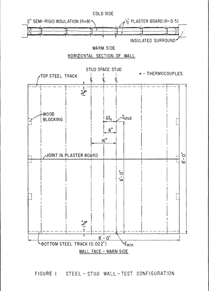
The thermal evaluation tests on the wood and steel frame walls were conducted in the DBR/NRCL Wall Panel Testing Unit. (6) The steel frame walls were constructed a s shown in Fig. 1; the steel studs investi- gated are shown in Fig. 2. The wood walls were constructed a s in Fig. 1 with nominal 2-in. by 4-in. wood studs. Table I sum- marizes the wall configurations tested, and the over-all thermal resistance and surface temper- ature characteristics measured.
The thermal performances of the steel frame walls were not as good a s those of the woocl walls, a s might be expected. Walls with the open-web studs compared more favourably with the wood walls than the solid-channel stud walls, because the open- web studs had a higher thermal resistance.
When the insulatioll thickness was less than the stud depth, wall thermal performance was affected by the location of the insulation. The dust marking p o t e 11
t i a 1 s (I,,,,,, AI,, and
AI,,,,,~) and condensation poten-
tial (ImI,,) of the steel walls were better with the insulation ad- jacent to the cold-side sheathing than with the insulation adja- cent to the warmside wallboard. Although the minimum sur- face temperature indices mea- sured on the steel walls were lower than the values for the ivood walls, they do not appear to be low enough to create any serious condellsation problems. Some coildensation should be an- ticipated, however, on the screw heads of the nralls with poor theimal performance, when the outdoor a i r temperature drops below O°F. while the indoor re- lative humidity is above 35 per cent.
S E C T I O N A
-
A '/2" PLASTERBOARD SHEATHING A N D BUILDING PAPER AIR SPACE VERTICAL A L U M I N U M O U T Sl
D E TORBALCONY CONCRETE FLOOR SLAB
V E R T l C A L S E C T 1 O N
3'/: LIGHT CHANNEL STEEL STUD (~0.022")
3'/2" FRICTION-FIT
GLASS FIBRE INSULATION
'Ip " PLASTERBOARD
I'IE:I,I) INVESTIGATION
The inside surfacc tempcrtl- tu1.e characteristics of steel frainc walls were measured with a scanning infrared rarliomctcr in f o u r highrise apartincnt buildings (Buildings A, B, C and D) in Edmonton during the win- t e r of 1971. A s a comparison, the temperature characteristic o C a wood frame wall was mea- s u ~ e d in a two-storey h o u s e
(B~liltling E ) in Ottawa. The four apartment buildiilgs stutlicd wcl-e similal. in design. They all had a concrctc struc- tural frame, an esterior steel- f r a m e infill \\,all, and hot-water baseboard convectors. The build- ings differed in the type of steel stud and exterior cladding used in the exterior wall. I n all f o u r buildings, the studs were doub- led adjacent to windows ant1 sliding patio doors, to provide greater structural support.
Details of the walls in Build- ings A, B. C, D, 1.: a r e sho~irll in Figures 3, 5, 7, 9 and 11, re- spectively. The walls in Ruild- ings A and C nscd light-channel steel st~irls (approximately 0.022 in. thick) ; thosc in Bui1dinfi.s C: and D used open-web welded-rod steel studs. The wall in Cuilding
E was a conventional frame of %in. by 4-in. ~vood studs.
The tcml)e~.atul.cs measul.cd
011 the inside surface of thc
walls, floors anrl ceilings in the five baildinrrs a r e shown a s in- dices in F1gs.4, 6, 8, 10 and 12. The baseboard heaters were off while surface temperatures were being measured in Cuilclings A,
E and E ; the heaters mere on in Euilrlings C and
I).
The measnre- ments in Buildings A and D were made with indoor anrl out- door a i r temperatures of all- proximately 70°F. and 30°F., respectively; measurements in Euilding E were made ~ v i t h in- door and ontdooi a i r temper- a t w c s ol' 70°F. and 10°F., rc- ~pectively.F I G U R E 5 B U I L D I N G B , E X T E R I O R W A L L D E T A I L
Some colt1 s t u d spaces occnr- red in this lvall; the cold spots were probably caused by impro- per installation of the insulation, ~vhich loas thinner than the 28 Specification Associate
BALCONY
-. . . . - - - .
INTERIOR
11
BALCONYD E T A I L A
C R E TE - S ~ A B - E X T
F l GU RE 6 B U l L D i N G B , INSIDE SURFACE TEMPERATURE INDICES
depth of the stud space. The minimum temperature index of
69 occurred over the intersec- tion of the window frame and the supporting double steel stud. Other cold locations were the wall surface adjacent to the elec- trical outlet ; the intersection of wall and concrete floor; and the stucls adjacent to the poorly in- sulated stud spaces.
llTllen these cold spots were ignored, the stud temperature indices were similar to the val- ues mcasured in the laboratory on the light-channel steel-stud trall. The space-centre indices, however, were much lower than the laboratory values and, a s a ~.csult, the fielcl value of AI,,,
which varied between 2 and 6, was smaller than the laboratory value of 10.
The surface temperature de- pression caused by the attach- ment screw ( A I,,,,,) was also much smaller than the labora- tory value of 6.
Building A llad been occupied for five years a t the time of the field study. Quite noticeable dust marking resulting from the heater was evident on the inside wall surface of a number of apartment units but there nras no apparent dust marking re- sulting from the steel studs.
.A more ,sr~.ious p~,oblem in
tllis and the other three apart-
ment buildings was the occur- rence of vertical cracks in the inside wallboard of the exterior walls and horizontal cracks a t the intersection of the wall and the plastered ceiling. The verti- cal cracks generally extended up- wards from the floor to the win- dow and from the window to the ceiling.
The most probable cause of the cracking was the transfer of load from the concrete structural frame to the inside plasterboarcl and/or the steel studs. The loat1 transfer b e t IV e e 11 structural
frame and infill wall was suffi- cient to break the fixed pane of
S E C T I O N
A
-
A-
3'18" OPEN-WEB WELDED-RODSTEEL FURRING
--
STEEL STUD ( ~ 0 . 1 5 " )STRIPS
SHEATHING A N D 3'12'' FRICTION
-
FITBUILDING PAPER GLASS FIBRE INSULATION
'12'' PLASTERBOARD
BASEBOARD CONVECTOR
RIGID INSULATION CONCRETE FLOOR SLAB
V E R T I C A L S E C T I O N
F I G U R E
7
B U I L D I N G C, E X T E R I O R W A L L D E T A I L* A T T A C H M E N T S C R E W INDEX
E X T E R I O R
WALL1
F GUR E
8
B U I L D
I NG
C,INSIDE SURFACE TEMPERATURE IYOICES
continued
f
?-om page 20glass in a numher of ~vindows. The wall cracking problem ap- pears to be characteristic of the s t ~ u c t u r a l system rather than the wall system, and might be rectifier1 by providing more ac- commotlation f o r movement a t the connection I~etnreen structure and wall.
Building I3 (Fig. 6 )
The wall inspected was relit-
til-fly f1.c~ of cold stud spaces.
This was probably the result of llsing an insulation t h a t com- plettly filled the stud space. SL11tl-sl)nc.(. tt>illl)ot.ntu~-c indictls
were slightly lower than the corresponding laboratory values f o r the light-channel wall, but the stud temperature indices were much higher than the la- boratory values. Itepresentative values of I,,,,, and AI,, were 87 and 4, respectively, con~pared with laboratory values of 78 and 16.
Tlle lon.cst surface tempt-t-a- f.urrs were measured a t ~ v a l l in- tersections and a t the intersec- tion of the mall and the A o o ~ slab above, which extended out- side t o form the balcoiiy. The wall surfaces adjacent to t h ~ clcctrical outlet ant1 o\,el. t h c
double studs supporting the n ~ i n - clow were also cold.
Building I3 hacl been occupied f o r two years a t the time of the study. There was no apparent dust mai-king resulting froin the steel studs, but cracks had oc- cburrecl on the inside wall sur- face. I11 one apartment, a crack \ r a s visihle in the floor slab im- medi;itely above a vertical crack
in the n~a11: the slab rl-ack was c o n t i n o ~ ~ s from inside to outside. This suggested that creep deflec- tion of the concrete Aoor slab may he one cause of the wall cracks.
S E C T I O N A
-
A
3'1~" OPEN-WEB WELDED-ROD STEEL STUD ( = 0.15") N O SHEATHING OR BUILDING PAPER 3'12" FRICTION-FITGLASS FIBRE INSULATlON AIR SPACE
'I2 " PLASTERBOARD
PRECAST CONCRETE
O U T S 1 D E
PRECAST BASEBOARD CONVECTOR
CONCRETE PANELS
CONCRETE FLOOR SLAB
SEAL
V E R T l C A L S E C T I O N
F I G U R E 9 B U I L D I N G D , E X T E R I O R W A L L D E T A I L
* A T T A C H M E N T S C R E W INDEX
continuer1 f ~ o m page 31 Building C (Fig. 8 )
The inside wall surface in this building was uniformly warm. Stud temperature indices were much higher than the values an- ticipated from t h e laboratory tests on the wall with open-web, welded-rod studs. This was par- tially due to the baseboard heat- ers being left on during the tein- perature measurements. Repre- sentative values of I
,,,,,
,
and AI,, were 89 and 2, respectively. The only cold location was the iiiter- section of the wall and the struc- tural column.Building C hacl beell occupied lor six years at the time of the study; the apartments had been
O U T S l D E FIBREBOARD SHEATHING AND BUILDING PAPER HORIZONTAL ALUMINUM SIDING
repainted three years previously and were due for another re- painting. There was no dust marking caused by steel studs, but noticeable dust marking had been caused by the heaters. The inner wall surfaces had the char- acteristic cracks.
Building D (Fig. 1 0 )
The stud-space temperature illdices were slightly lower than might be expected for a wall with full-thickness insulation. The stucl i~idices nrei-e lower than the values ineasured on the wall of Building C tliat had the same open-web, welclecl-1.0~1 studs. This was probably clue to the abseiicc of sheathing on the out- er face of the studs. Rel~i~eseu- H O R I Z O N T A L S E C T I O N
F I G U R E 11 B U I L D I N G E , E X T E R I O R W A L L D E T A I L
*
tative values of 1
,,,,,
and A l,, were 8.5 and 5, respectively.Cold wall surfaces occurred over the double studs support- ing the patio door, a t the inter- section of the wall and ceiling, and adjacent to the electrical outlet.
Euiltiiiig D had beell occupied Sol. three years at the time of the study, ant one of the apart- ments that had qot been repaint- cd during this period sho~ved light dust marking over the studs. The dust marking was so slight that it would probably not become objectionable before the next repainting.
Wall cracks and water stain marks caused by rain penetra- tion were much more objection- able. The dust marking in this one apartment could have been a reflection of the occupancy rather than the design of the wall system, since the tempera- ture performance of this wall differed very little from those of the walls in Buildings A and B. I N S 1 D E
2" x 4" WOOD STUD
2 I/," PAPER-BACKED
GLASS FIBRE INSULATION
.---
-
-.
* -.- .,-
, -- \ .- -. 1.
--. L 1---.. , / ,.
,-
,_
-
\ - - --
\. , Building E (Fig. 12)#I-
'/2" PLASTERBOARD L=Y----
*The temperature over the in- side wall surface was quite uni- form, but low temperature indi- ces occurred where the wall in- tersected the floor, the ceiling or another wall. The wall surface adjacent to the electrical outlet was also cold.
-<.
<
\ \ *>'
..
-
-.-
I -SUMMARY17 ( 1 ) The temperature perfor- mances of the steel walls in thc
' S \Irere
four apartment building
quite similar. None of the ~valls experienced horizontal temper- ature differences as large a s those indicated by the laboratory tests.
Cold spots occurred where there \\-ere iiisulation flaws, ~ v h e r e insulation was nlissing or where a i r was leaking inwarcls. These were usually located near electrical outlets, arouiicl the windon. perimeter, and a t the in- tersectioil of the exterior wall alid the floor, ceiling or another wall.
None of the walls experienced inside surface temperat~wcs that
F I G U R E 12 B U I L D I N G E , WOOD STUD WALL, INSID.€ SURFACE TEMPERATURE INDICES
were low enough to create a po- tential condensation problem, unless the outdoor a i r tempera- t u r e dropped well below O ° F . I t is quite possible, however, t h a t condensation would occur with- in the wall space a t electrical out- lets and around window perimet- ers where moist indoor a i r could leak outwards.
O ( 2 ) The laboratory investi- gation indicated t h a t a low dust marking potential could be achieved by using a n insulation with a thicliiless less t h a n the depth of the stud space and by locating this insulation against the outside sheathing board.
The field study showed, how- ever, t h a t such a n insulation lay- e r was more difficult to install correctly in a wall t h a n a thicker insulation layer t h a t completely filled the stud space.
( 3 ) The field study indicated
t h a t exterior f r a m e walls built with light-channel or open-web steel studs and having either fully insulated stud space or
2% in. of insulation towards the
cold side a r e no more suscep- tible t o dust marking or conden- sation than a wood f r a m e wall with 21/!! in. of insulation to- wards the w a r m side.
Walls, such a s t h a t in Build- ing C, with fully insulated stud spaces, low conductance steel studs, and added thermal resis- tance on the outerface of the studs appear to perform even better t h a n a wood wall such a s t h a t in Building E.
( 4 ) The study shpved t h a t better accommodation of move- ment must be provided between non-loadbearing infill walls and a coilcrete structural f r a m e in order to prevent cracking of the inside wall finish.
REFERENCES
1. Sasaki, J. R. Thermal perform- ance of steel-stud exterior walls. Na- tional Research Council of Canada, DBR Building Research Note, No. 77, August 1971.
2. Handegord, G. 0. and N. B. Hut- cheon. Thermal performance of frame walls. ASHVE Trans., Vol. 58, 1952, p. 171.
3. Handegord, G . 0. and N. B. Wut- cheon. Thermal performance of frame walls, Part 11, ASHVE Trans., Vol. 59, 1953, p. 449.
4. Handegord, G . 0. Thermal per-
formance of frame walls, Part 111. ASHRAE Journal, Heating, Piping and Air Conditioning, June 1957, p. 145.
5. Nielsen, R. A. Dirt patterns on walls. ASHVE Trans., Vol. 46, 1940, p. 247.
6 . Solvason, K. R. Large-scale wall
heat-flow measuring apparatus. ASH- RAE Trans., Vol. 65, 1959, p. 541.