HAL Id: hal-02086009
https://hal.univ-lorraine.fr/hal-02086009
Submitted on 1 Apr 2019
HAL is a multi-disciplinary open access
archive for the deposit and dissemination of
sci-entific research documents, whether they are
pub-lished or not. The documents may come from
teaching and research institutions in France or
abroad, or from public or private research centers.
L’archive ouverte pluridisciplinaire HAL, est
destinée au dépôt et à la diffusion de documents
scientifiques de niveau recherche, publiés ou non,
émanant des établissements d’enseignement et de
recherche français ou étrangers, des laboratoires
publics ou privés.
Spin transfer torque magnetization reversal in a
hard/soft composite structures
M Kuteifan, C.-H Lambert, M Lubarda, V. Lomakin, E. Fullerton, S. Mangin
To cite this version:
M Kuteifan, C.-H Lambert, M Lubarda, V. Lomakin, E. Fullerton, et al.. Spin transfer torque
magnetization reversal in a hard/soft composite structures. AIP Advances, American Institute of
Physics- AIP Publishing LLC, 2018, 8, pp.015024. �10.1063/1.5009589�. �hal-02086009�
AIP Advances 8, 015024 (2018); https://doi.org/10.1063/1.5009589 8, 015024 © 2018 Author(s).
Spin transfer torque magnetization reversal
in a hard/soft composite structures
Cite as: AIP Advances 8, 015024 (2018); https://doi.org/10.1063/1.5009589
Submitted: 17 October 2017 . Accepted: 09 January 2018 . Published Online: 25 January 2018 M. Kuteifan , C.-H. Lambert, M. V. Lubarda, V. Lomakin, E. E. Fullerton, and S. Mangin
ARTICLES YOU MAY BE INTERESTED IN
Estimation of thermal stability factor and intrinsic switching current from switching distributions in spin-transfer-torque devices with out-of-plane magnetic anisotropy
AIP Advances 8, 015011 (2018); https://doi.org/10.1063/1.5002139
Efficient micromagnetic modelling of spin-transfer torque and spin-orbit torque
AIP Advances 8, 056008 (2018); https://doi.org/10.1063/1.5006561
Spin-orbit torque-induced switching in ferrimagnetic alloys: Experiments and modeling
AIP ADVANCES 8, 015024 (2018)
Spin transfer torque magnetization reversal in a hard/soft
composite structures
M. Kuteifan,1,2,aC.-H. Lambert,1M. V. Lubarda,3,2V. Lomakin,2
E. E. Fullerton,2and S. Mangin1,2
1Institut Jean Lamour, UMR CNRS 7198, Universit´e de Lorraine, 54506 Vandoeuvre l`es Nancy,
France
2Center of Memory and Recording Research, University of California, San Diego, California
92093-0401, USA
3Faculty of Polytechnics, University of Donja Gorica, Oktoih 1, 81000 Podgorica, Montenegro (Received 17 October 2017; accepted 9 January 2018; published online 25 January 2018)
Current induced magnetization manipulation in a spin valve structure where the free layer is a magnetic hard/soft composite structure is studied using micromagnetic sim-ulations. In this structure where the hard layers has strong perpendicular magnetic anisotropy, a domain wall can be nucleated in the soft layer due to the spin trans-fer torque effect. Depending on the magnetic properties of the layers and the current intensity the domain wall can induce the free layer reversal or be pinned by the hard layer. For these non-uniform magnetic configurations both bulk and interface spin transfer torques need to be considered. The potential reduction of the critical current observed in this geometry is of potential technological interest. © 2018 Author(s).
All article content, except where otherwise noted, is licensed under a Creative Commons Attribution (CC BY) license (http://creativecommons.org/licenses/by/4.0/).
https://doi.org/10.1063/1.5009589
It is now well established that due to spin transfer torque (STT), a polarized current can induce magnetization switching or precession. Those effects are promising technologies for two different application STT-MRAM (magnetic random access memories) and STT-NO (nano-oscillators). One of the present challenges to implement STT-MRAM lies on the reduction of the critical current whereas STT-NO depends on the maximum output power and the narrower frequency bandwidth of the oscillations possible. To improve these two technologies many studies have been performed to find optimal materials and geometries. For instance perpendicular magnetic anisotropy (PMA) materials have shown to improve both switching current for STT-MRAM1,2and the output power for STT-NO.3,4However up to now, most of the studies have considered free layers with uniform magnetization.
More complex structures like hard/soft magnetic bilayers were studied for their interesting magnetic properties5,6 and magnetic recording performance.7–10 In this case using an external magnetic field and depending on the bilayer structure a domain wall nucleated in the soft layer can be pinned or propagate through the hard layer. If pinned the domain wall can then be com-pressed on the energy barrier created by the hard layer.6 For applications, it was shown using a macrospin model that such structures could provide a lower switching field for a given thermal stability.11
In this Letter, we are studying the effect of spin transfer torque on a perpendicular hard/soft structure. Our goal is to answer basic questions such as can a domain wall be nucleated, pinned, and compressed by a polarised current as it is possible with a magnetic field? Do we have to consider both interface and bulk spin transfer torques? As well as more technology related questions such as how is the switching current affected by the hard/soft structure?
aemail:[email protected]
015024-2 Kuteifan et al. AIP Advances 8, 015024 (2018)
We used the FastMag micromagnetics code12to simulate the behaviour of a spin valve containing a hard/soft composite free layer under an applied polarized current. The z axis is defined as the direction along the magneto-crystalline anisotropy axis, perpendicular to the film plan. Current is regarded as positive when electrons are flowing in the +z direction.
The first sample geometry considered is a pillar structure with a 5x5 nm2section. Its magnetic
structure is divided in two blocks: a 5nm-thick polarizer (reference layer) and a 7 to 20 nm-thick composite free layer, separated from each other by a 1 nm non-magnetic spacer. The reference and free layers are considered fully decoupled with respect to the exchange interaction, which allows us to focus on the influence of the polarized current flowing through the composite free layer. All layers have PMA along the z axis. The composite free layer is made of a soft and hard sublayer having respectively a uniaxial magnetic anisotropy constants KS = 1.5⇥104 erg/cm3 and KH = 1.5⇥107
erg/cm3, and a saturation magnetization M
S= 800 emu/cm3and MH= 200 emu/cm3, respectively.
The damping parameter was chosen to be ↵=0.05. The initial magnetization of the reference layer and the free layer are along -z and +z directions, correspondingly.
The micromagnetic simulations are based on the solution of the Landau-Lifshitz-Gilbert-Slonczewsky (LLGS) equation modified to take into account the effect of both the spin-transfer torque in the bulk13 as well as the spin-transfer torque at the interface.14The LLGS equation is written as: @M @t = ⇣ Heff + Hstt ⌘ ⇥ M +M↵ SM ⇥ @M @t u @M @z + u MSM ⇥ @M @z
where M is the magnetization, is the gyromagnetic ratio, Heffis the effective field derived from the
energy functional, Hsttis the field derived from the Slonczewsky formulation for interfacial STT
effects, ↵ is the damping parameter, MS is the saturation magnetization, is the non-adiabatic
spin-transfer parameter. The parameter u depends on the current density J and is defined as
u= gJµBpB/(2eMS), where g is the Land´e factor, µBis the Bohr magneton, e is the electron charge,
and pbis the polarization factor of the current in the bulk of the material. The interfacial STT field is
written as Hsst= jpi~/(2etMS)M ⇥ p where piis the polarization factor of the current at the interface,
~is the reduced Planck constant, t is the effective thickness related to the mesh size14and p is the magnetization of the reference layer. The finite elements simulations were done using a cell size of 1 nm.
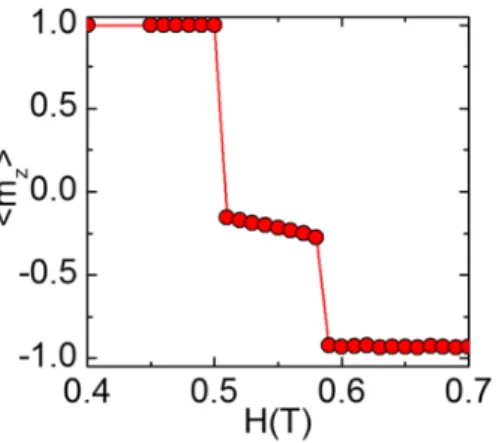
For purposes of later comparison, we first consider the magnetization response of a 15-nm-thick soft layer and a 5-nm-thick hard layer under the influence of an external magnetic field and in the absence of current through the stack. Figure1shows that an external field applied to this structure can lead to a DW nucleation in the free layer, compression of the DW when the field is increased, represented by the fact that the average z component of magnetization gets lower, and eventually its propagation through the hard layer when the field becomes strong enough. All these observations are in accordance with typical calculations involving applied magnetic fields.6,15
FIG. 1. Average of the z component of the magnetization in the 5x5x20nm3composite free layer as a function of a field applied along the z axis, in the absence of current.
015024-3 Kuteifan et al. AIP Advances 8, 015024 (2018)
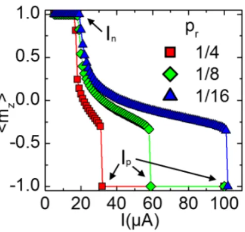
FIG. 2. Average of the z component of the magnetization in the 5x5x20nm3composite free layer as a function of applied current for different polarization ratios pr..
Figure2shows that similarly to an applied field, current can lead to DW nucleation, compression and propagation6owing to spin transfer torque. Since the magnetization along the thickness of the free layer is not uniform, continuous spin transfer torque within this layer has to be accounted for in the calculations. In our model, the interfacial and bulk contributions to the spin transfer torque are modulated separately by introducing an efficiency coefficients for the STT in the bulk of the layers and for STT at the interface. Two distinct STT polarizations, therefore, appear in the model:
pifor the interfacial STT and pbfor the bulk STT. The relative efficiency of bulk STT with respect
to interfacial STT we represent using the ratio pr = pb/pi. For these cases piwas chosen to be 1.
The physical behaviour of the DW is qualitatively similar for various values of pr. However this
parameter can be tuned to adapt the device to adequate values of applied current depending on different technology and materials.
From the reversal curves in Fig.2, two characteristic current values can be extracted: the nucle-ation current Inthat corresponds to the minimum current required to nucleate a domain wall in the
structure corresponding to hmzi<1, and the propagation current Ipthat indicates the complete reversal
of the free layer. Between the two stages, the pillar is in a current-sustained state which exhibits a domain wall in the soft part of the free layer. The bulk STT tends to push the DW towards the hard layer and compress it, while the exchange interaction opposes this compression. Similarly to what happens under an applied field, DW compression becomes greater when the current (and hence bulk STT) is increased. The bulk STT, therefore, has a large impact on Ipwhere larger values of pr will
lead to reversal at less current.
Figure3highlights the influence of the soft sublayer thickness tSon Inand Ipfor two values of pr
while keeping the hard sublayer thickness constant to 5 nm. Increasing the soft layer thickness from a small value strongly decreases Inand Ipas the switching is facilitated. For tS>10nm, Inbecomes
relatively stable. The nucleation of a tilt in the free layer essentially comes from the interfacial spin transfer interaction with the reference layer, hence the small difference between pr = 1/4 and pr= 1/8. On the other hand, Ipstrongly depends on bulk STT to push the domain wall through the
hard sublayer. For this reason Ipis greatly reduced for pr= 1/4. We can observe that Ipsaturates for
large enough values of tS.This is explained by the fact that once a domain wall is fully nucleated, it
can be pushed through an arbitrarily long distance by bulk STT in an ideal case with no defect. In the case of magnetic field-driven reversal, composite structures can improve the efficiency of the switching process.15–20Calculations were performed in order to investigate the role of hard and soft thicknesses on optimization of switching current and thermal stability of such systems. The model involves a 7-nm-thick free layer with tSranging from 0 to 7 nm and tH= 7 nm -tS. The cross
sectional area of the stack is 5x5 nm2and the reference layer is 3-nm thick. The anisotropies for the
hard and soft layers being used are KH= 1.5⇥107erg/cm3and KS= 1.5⇥106erg/cm3, respectively.
015024-4 Kuteifan et al. AIP Advances 8, 015024 (2018)
FIG. 3. Evolution of the nucleation current Inand the propagation current Ipdepending on the soft sublayer thickness for two values of the polarization ratio pr.. The cross section is 5x5nm2and the hard sublayer thickness is 5nm.
free and reference layer are 800 emu/cc and 200 emu/cc, respectively. The damping parameters were chosen to be ↵f=0.02 for the free layer and ↵r=1 for the reference layer.
For each structure corresponding to the different values of tS, the thermal stability was
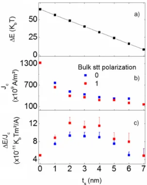
calcu-lated by the nudged-elastic-band (NEB) method using FastMag simulator.12,21This method finds the minimum energy path between the initial (free layer up) and final (free layer down) states of the stack, from which we obtain the energy barrier E (Fig.4a). This barrier gives the thermal stability of the system. It corresponds to the minimum amount of thermal energy required to switch the free
FIG. 4. (a) Energy barrier E of the minimum energy path for the reversal of the composite free layer as a function of soft layer thickness. (b) Eritical current density Jcfor reversal of the free layer as a function of soft layer thickness for a bulk stt polarization of 0 and 1. (c) switching efficiency defined as E/Jc. Figures obtained for the case of a 5x5x7nm3free layer.
015024-5 Kuteifan et al. AIP Advances 8, 015024 (2018)
layer. The mode of thermally driven reversal for the modelled structures is uniform rotation of the magnetization, and E decreases linearly with tS, as expected.
The critical current density for switching Jcwas obtained by solving the LLG equation for two
cases: in one case, the bulk STT polarization was set to 1, and in the other case, it was ignored (polarization set to 0). In both cases the interfacial STT polarization was set to 1. Comparison of the two cases will highlight the effect of the bulk STT on the reversal process.
For tS= 0 or tS = 7 (completely hard or completely soft free layer) there is no magnetization
gradient along the thickness during the reversal of the layer. For this reason the bulk STT has no effect on this process and the critical current densities are identical for the two cases considered. For intermediate values of tS, nonuniformities of magnetization can develop, due to the interface
between the soft and hard layers. In these cases, bulk STT helps the magnetization configuration of the free layer to propagate into the hard layer, making it easier to switch. As a result, Jcis smaller
when the bulk STT polarization is 1 instead of 0 (Fig.4b). Figure4cshows E/Jcas a function of tS.
This ratio is commonly regarded as the switching efficiency:22a high value indicates a device less effected by the trade-off between thermal stability and critical current necessary for switching (power consumption). For both considered polarization values, it is shown that there is a peak in switching efficiency for tSbetween 2 and 4 nm. The efficiency is greater when bulk STT is taken into account.
This can be explained by looking at the reversal mechanism. The polarizer is interfaced with the soft part of the free layer, where the electrons induce the switching. In these cases the exchange interaction keeps the magnetization uniform through the soft layer, however the difference in anisotropy with the hard layer creates a small angle between both magnetization vectors: it takes longer for the hard layer to switch. When bulk STT is added to the system, the electrons tend to polarize the hard layer (into which they flow) towards the same direction as the soft layer (from which they come), thus effectively helping the switching process.
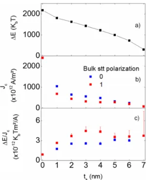
Hard/soft composite structures with a larger cross sectional area of 50x50nm2have been studied,
as well, in order to highlight the effect of lateral size on device characteristics (see Fig.5). The same
FIG. 5. (a) Energy barrier E of the minimum energy path for the reversal of the composite free layer as a function of soft layer thickness. (b) Critical current density Jcfor reversal of the free layer as a function of soft layer thickness for a bulk stt polarization of 0 and 1. (c) Switching efficiency defined as E/Jc. Figures obtained for the case of a 50x50x7nm3free layer.
015024-6 Kuteifan et al. AIP Advances 8, 015024 (2018)
thickness of 3 nm was kept for the reference layer. The free layer thickness, as in the earlier case was 7 nm, with tSranging from 0 to 7nm and tH= 7-tS. The anisotropies for the hard and soft layers
were KH= 3.0⇥107erg/cm3and KS= 3.0⇥106erg/cm3, respectively. The anisotropy of the reference
layer, saturation magnetization and damping constant were kept the same as the previous case. The minimum energy paths for the reversal of these structures were calculated by the NEB method as for the smaller model, from which the energy barriers E we obtained (Fig.5a). Unlike the results for the 5x5-nm2cross-section model, the thermal reversal mode for the larger structures is no longer
uniform magnetization rotation, except for ts = 7 nm where the entire free layer is magnetically
soft. As soon as the hard sublayer is introduced, the optimal reversal path involves domain wall propagation across the pillar in the lateral direction, as detailed elsewhere.23As a consequence, the gain in switching efficiency is much less apparent. When the bulk STT polarization is set to 1, a maximum can be observed for a soft layer thickness around 3 nm. However, the efficiency is only slightly decreased if bulk STT is excluded all together. These results emphasize how the reversal mode, properties of each sublayer, and their interaction can come to bear in the design of devices optimized for low power consumption and high thermal stability.
In conclusion we have shown that composite layers made of sublayers with different anisotropy values can enhance the switching properties under an applied current in order to reduce the critical switching current and keep a good thermal stability. Moreover, the switching threshold and range of domain wall stabilization depend on the bulk spin transfer torque polarization as well as the interfacial spin transfer torque polarization coefficients. The gain in current efficiency in hard/soft structures studied is larger when lateral sizes are smaller and the current-driven reversal is more uniform.
This work was supported by the French Agence Nationale de la Recherche, ANR-10-BLANC-1005 “Friends” by the ANR-NSF Project, ANR-13-IS04-0008-01, "COMAG" by the ANR-Labcom Project LSTNM, by the European Project (OP2M FP7- IOF-2011-298060) and by the Universit´e de la Grande, Institut Carnot ICEEL, the Region Grand Est and Grand Nancy. Work at UCSD supported by the NSF award DMR #1312750.
1S. Mangin et al.,Nature Mat.5, 210 (2006). 2S. Mangin et al.,Appl. Phys. Lett.94, 012502 (2009).
3D. Houssameddine et al.,Nature Materials6(6), 447–453 (2007). 4Z. Zhongming et al.,Scientific Reports3 (2013).
5E. E. Fullerton et al., Phys. Rev. B 58, 00742 (1998). 6S. Mangin et al.,Phys. Rev. B58(5), 2748 (1998). 7N. F. Supper et al.,IEEE Trans. Magn.41, 3238 (2005). 8E. E. Fullerton et al., U.S. patent 7,425,377 (Sept. 16, 2008). 9R. H. Victora et al.,IEEE Trans. Magn.41, 2828 (2005). 10D. Suess et al.,Appl. Phys. Lett.87, 12504 (2005). 11I. Yulaev et al.,Appl. Phys. Lett.99, 132502 (2011).
12R. Chang et al.,Journal of Applied Physics109(7), 07D358 (2011). 13A. Thiaville et al.,Europhys. Lett.69(6), 990–996 (2005). 14J.-G. Zhu, IEEE Trans. on Magnetics 40(1) (2004). 15A. Dobin et al.,Appl. Phys. Lett.89, 062512 (2006). 16D. Goll et al.,Phys. B403, 338–341 (2008). 17D. Suess,Appl. Phys. Lett.89, 113105 (2006).
18S.-S. Yan et al., J. Mag. Magn. Mat. 210, 309–315 (2000). 19J.-P. Wang et al.,Appl. Phys. Lett.86, 142504 (2005). 20K. Mibu et al.,J. Mag. Magn. Mat.163, 75–79 (1996). 21D. Suess et al.,J. Mag. Magn. Mat.321, 545–554 (2009). 22J. Z. Sun et al., Phys. Rev. B 88, 104426 (2013).