HAL Id: hal-02330910
https://hal.archives-ouvertes.fr/hal-02330910
Submitted on 24 Oct 2019
HAL is a multi-disciplinary open access
archive for the deposit and dissemination of
sci-entific research documents, whether they are
pub-lished or not. The documents may come from
teaching and research institutions in France or
abroad, or from public or private research centers.
L’archive ouverte pluridisciplinaire HAL, est
destinée au dépôt et à la diffusion de documents
scientifiques de niveau recherche, publiés ou non,
émanant des établissements d’enseignement et de
recherche français ou étrangers, des laboratoires
publics ou privés.
3D Hybrid Model of the Axial Flux Motor Accounting
Magnet Shape
Théo Carpi, Yvan Lefèvre, Carole Hénaux, Jean-François Llibre, Dominique
Harribey
To cite this version:
Théo Carpi, Yvan Lefèvre, Carole Hénaux, Jean-François Llibre, Dominique Harribey. 3D Hybrid
Model of the Axial Flux Motor Accounting Magnet Shape. COMPUMAG, Jul 2019, Paris, France.
�hal-02330910�
3D Hybrid Model of the Axial Flux Motor Accounting Magnet Shape
T. Carpi, Y. Lefèvre, C. Hénaux, J.F. Llibre and D. Harribey
Laboratoire Plasma et Conversion d’Energie (LAPLACE), University of Toulouse, CNRS, 31000 Toulouse, France
This paper presents a generalization of an analytical model of an axial flux permanent magnet machine to any magnet shape. It uses an existing model which computes the 3D magnetic flux density by the separation of variables and finite difference method. The original magnet shape is modified by adding a radial dependence to the arc pole. It will be shown that this radial dependency has no impact on the problem’s resolution. As an example, the model will be computed for a circular magnet shape and will be compared to a finite element analysis.
Index Terms— Axial flux, finite difference method, Fourier series, magnetic scalar potential, magnet shape, permanent magnet,
separation of variables.
I. INTRODUCTION
HE structures of Axial Flux Permanent Magnet (AFPM) machine structures are still under development [1]. Thus, modeling some of their particularities is becoming an issue. In axial flux surface mounted permanent magnet machines, permanent magnets are often considered as sector shaped magnets (trapezoidal form like in Fig. 1). However others magnet shapes can be found in some AFPM structures [1], [2]. Nevertheless, considering 3D analytical modeling, despite the variety of the methods used, only sector shaped magnets have been considered [3], [4], [5].
This paper proposes to generalize the model described in [5] which considers sector shape magnets with regard to different magnet shape. A radial dependence of the arc pole is put forward. From the mathematical point of view, it will be shown that this radial dependency of the arc pole has no impact on the development of the initial solution. Subsequently, the solution will be computed for circular shaped magnets and compared to FEA.
II. THE AXIAL FLUX SURFACE MOUNTED PERMANENT
MAGNET MACHINE
A representation of a pair of poles of a surface mounted permanent magnet axial flux motor is shown in Fig. 1.
The 3D hybrid analytical finite difference (FD) model presented in [5] is easy to set up. Furthermore, it is also valid for modeling multi-stage machines thanks to the image method. This paper proposes to extend this model to more complex magnet shapes.
Fig. 1. A 3-D representation of a pair of poles of the AFPM machine.
III. GENERALIZATION OF THE MAGNET SHAPE
In [5], the arc pole αp is constant. The method can be extended to complex magnet shapes as the example shown in Fig. 2. For this type of magnet shape the arc pole can be described as a function of the radial position r. This paper will compute the axial magnetic flux density Bz in the same way it is done in [5] adding this radial dependency of the arc pole
αp(r). The arc pole is computed for each discretized radius. This discretization is performed by the 1D FD method developed in [5].
Fig. 2. Complex magnet shapes with arc pole depending on radial position.
As in [5], the following assumptions are made:
- Because of the air-space between the magnets, we assume that the permeability of magnets and the air is the same and equal to µ0.
- Back-irons have infinite permeability so the boundary conditions (BC) at the planes z = 0 and z = hm + g are taken as normal flux boundary conditions. Where g is the airgap width and hm the permanent magnet width.
- The problem is limited in the radial direction with parallel flux boundary conditions on cylinders at r = R0 and r = R1.
Using magnetic scalar potential formulation (MSP), Ω, the partial differential equation to be solved is deduced from Maxwell equations:
∆Ω = 𝑑𝑖𝑣 𝑴 (1) To reduce the number of regions to consider, the image method is used to replace the normal flux BC by a periodical extension in the axial direction. This leads to a double Fourier
series description of the magnetization of the permanent magnets in the azimuthal and axial directions:
𝑀𝑧(𝑟, 𝜃, 𝑧) = ∑∞𝑛=1,3,5 ∑ 𝑀𝑛𝑘(𝑟) cos 𝑛𝑝𝜃 . cosℎ𝑘𝜋 𝑚+𝑔𝑧 ∞ 𝑘=1 + ∑∞𝑛=1,3,5𝑀𝑛0cos 𝑛𝑝𝜃 (2) with
𝑀
𝑛𝑘=
𝑛𝑘𝜋8 𝑀2sin (𝑘𝜋
ℎ𝑚 ℎ𝑚+𝑔) sin (
𝑛𝜃𝑝(𝑟) 2)
(3)𝑀
𝑛0=
ℎ𝑚 ℎ𝑚+𝑔 4𝑀 𝑛𝜋sin (
𝑛𝜃𝑝(𝑟) 2)
(4)where p is the number of pole pairs and Mnk and Mn0 are the Fourier series coefficients.
Therefore, there are three regions to be considered separated by cylindrical surfaces at r = Rint and r = Rext. Air regions I (Rint ≥ r ≥ R0) and III (R1 ≥ r ≥ Rext), and the PM region II (Rext
≥ r ≥ Rint). The new magnet shape has to be included in the magnet region between Rint and Rext. The radial dependency of
αp(r) implies that the Fourier series coefficients are now r dependent.
All the magnets are axially magnetized. Therefore, the magnetization 𝑴 has only a component in the axial direction. The second member of the equation is reduced to:
𝜕𝑀𝑧 𝜕𝑧 = ∑ ∞ 𝑛=1,3,5 ∑ (−ℎ𝑘𝜋 𝑚+𝑔) 𝑀𝑛𝑘(𝑟)𝑐𝑜𝑠(𝑛𝑝𝜃) . 𝑠𝑖𝑛 ( 𝑘𝜋 ℎ𝑚+𝑔𝑧) (5) ∞ 𝑘=1
Here, the partial derivative in accordance with the axial coordinate has no influence over the arc pole αp(r).
The method of separation of variables used in [5] is still valid even if the arc pole αp(r) depends on the radial position. The final expression of the axial magnetic flux density is now:
𝐵𝑧= −𝜇0(∑∞𝑛=1,3,5 ∑ 𝑣𝑛𝑘cos(𝑛𝑝𝜃) . (ℎ𝑘𝜋 𝑚+𝑔) cos ( 𝑘𝜋 ℎ𝑚+𝑔𝑧) ∞ 𝑘=1 + 𝑀𝑧(𝑟, 𝜃, 𝑧)) (6)
where vnk are functions of 𝑟. Differential equations are solved by FD method for each azimuthal n and axial k harmonics to compute these functions. The 1D FD method discretizes the problem in the radial direction.
IV. COMPARISON WITH FEA
As an example, circular magnet shape will be considered in this study as shown in Fig. 3. For each discretized radius, the arc pole is calculated in order to create a circular shape.
Fig. 3. 3-D view of the AFPM machine with circular shaped magnets.
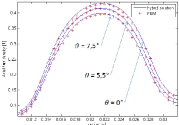
Fig. 4. Axial flux density as a function of the radial coordinate computed by hybrid analytical-FD method and FEM.
The FEA is carried out on ANSYS/Emag 3D [6] and based on a magnetic scalar potential formulation. The FEA is done under the same condition as the model, that means on one pair of poles of the machine and the same assumptions are made (the permeability of the magnets and BC).
Both computation methods are compared on a radial line at
z = hm + g/2 and for several angles θ = 0 (in front of the symetrical axis), θ = 5.5° and θ = 7.5°.
The results are computed for 16 harmonics. The root mean square (RMS) error between the hybrid model and the FEA on Fig. 4 are about 1.2% for the three plots. The RMS errors are below 2% if we consider the influence of θ and z independently. Back electromotive force and torque can be easily computed from the Bz component of the magnetic flux density [5].
V. CONCLUSION
This paper presents a generalization of a 3D analytical model of AFPM with sector shaped magnets to AFPM with more complex magnet shapes. The method is validated with circular shaped magnets.
VI. REFERENCES
[1] M. Shokri, N. Rostami, V. Behjat, J. Pyrhönen, M. Rostami, "Compari-son of performance characteristics of axial-flux permanent magnet syn-chronous machine with different magnet shapes", IEEE Trans. Magn., vol. 51, December 2015.
[2] M. R.A. Pahlavani, Y. S. Ayat, A. Vahedi, "Minimisation of torque ripple in slotless axial flux BLDC motors in terms of design considerations", IET Electr. Power Appl., 2017, Vol. 11, Iss. 6, pp. 1124–1130.
[3] Y. Huang, B. Ge, J. Dong, H. Lin, J. Zhu, Y. Guo, "3-D analytical mod-eling of no-load magnetic field of ironless axial flux permanent magnet machine", IEEE Trans. Magn., vol. 48, no. 11, pp. 2929-2932, Nov. 2012.
[4] Ping Jin, Yue Yuan, Miyi Jin et al., "3-D analytical magnetic field analy-sis of axial flux permanent magnet machine", IEEE Trans. Magn., vol. 50, no. 11, pp. 3504-3507, 2014.
[5] T. Carpi, Y. Lefevre, C. Henaux, “Hybrid Modeling Method of Magnetic Field of Axial Flux Permanent Magnet Machine,” 2018 XIII
Interna-tional Conference on Electrical Machines (ICEM), Alexandroupoli,
Greece Sept. 2018.
[6] ANSYS Mechanical APDL Low Frequency Electromagnetic Analysis 215 Guide. Release 17.2 documents, Aug. 2016.