30 to 50 ns liquid-crystal optical switches
The MIT Faculty has made this article openly available.
Please share
how this access benefits you. Your story matters.
Citation
M. W. Geis, R. J. Molnar, G. W. Turner, T. M. Lyszczarz, R. M. Osgood,
and B. R. Kimball (2010). 30 to 50 ns liquid-crystal optical switches.
Proc. SPIE 7618: 76180J/1-5. ©2010 COPYRIGHT SPIE--The
International Society for Optical Engineering
As Published
http://dx.doi.org/10.1117/12.840281
Publisher
SPIE
Version
Final published version
Citable link
http://hdl.handle.net/1721.1/58583
Terms of Use
Article is made available in accordance with the publisher's
policy and may be subject to US copyright law. Please refer to the
publisher's site for terms of use.
30 to 50 ns Liquid-Crystal Optical Switches
M. W. Geis, R. J. Molnar, G. W. Turner, and T. M. Lyszczarz
Lincoln Laboratory, Massachusetts Institute of Technology, Lexington,
Massachusetts 02420-9108, USA
R. M. Osgood and B. R. Kimball
Natick Laboratory Army Research, Development and Engineering Center
Natick, Massachusetts 01760-5000, USA
ABSTRACT
The optical switching times of liquid-crystal cells using 5CB, 5OCB and PCH5 liquid crystal materials have been characterized as a function of applied voltage, V, and temperature, T. The transition time from 90 to 10 % transmission scales as V-2 and is limited to 50 to 30 ns by the breakdown electric field, ~ 106 V cm-1 of the liquid crystal. The time
from the initial voltage step to 90 % transmission, delay time, decreases with increasing voltage and approaches a constant value at higher electric fields, >105 V cm-1. Both the transition and delay times decrease with increasing
temperature. The minimum transition times at temperatures a few degrees below the nematic-isotropic temperatureare 32, 32, and 44 ns and delay times are 44, 25 and 8 ns for 5CB, 5OCB, and PCH5 respectively.
Keywords: liquid crystal, optical switches
1. INTRODUCTION
Large area, > 0.1 cm2, fast, < 1 ms, optical shutters have applications in recording images of laser and
chemically driven explosions. Mechanical shutters have frame rates of up to 25x106 fps for 125 frames1 and the simpler
and more compact electronic shutters using a gated charge-coupled-device, CCD, array have frame rates of 2x10⁶ fps
for 50 frames.2 This article reports on a simple twisted-nematic liquid-crystal shutter with demonstrated shutter times of
30 to 50 ns. This fast switching when combined with a CCD array could represent a third approach with frame rates exceeding 106 for more than a 1000 frames.
Liquid crystal shutters are limited by two time constants: the switching time to rotate the liquid-crystal directorate under the application of an electric field and the recovery time after the electric field is removed. While the recovery time is entirely dependent upon the properties of the liquid crystal, the switching time also depends on the applied electric field. For repetitive optical systems, as with flat panel displays, both the switching and recovery times are important, but for recording one-time images only the switching time is important. This article addresses the limitations in the switching times for twisted-nematic liquid-crystal, 5CB, 5OCB and PCH5, shutters.
2. EXPERIMENT
The liquid-crystal cells used with these experiments have an active area of 0.1 cm2 and gap thickness of either 5 or
10 μm. The cell walls consisted of 10 Ω/square ITO-coated 2.5x2.5-cm glass plates from a commercial source. Small surface hillocks in the ITO, which limited the cell breakdown voltage, were removed using a syton polish. Standard photolithography and wet chemical etching using one of several etching solutions,3 5 ml of HNO
3, 20 ml HCl, and 75
ml DI at 60 °C, were used to pattern the ITO film. A stencil mask and E-beam evaporation were used to form a patterned metal film, comprising 10 nm Ti, 100 nm Al, and 10 nm Ti, which provided electrical contact and decreased the cell resistance. Additional lithography was used to define a 5 μm-thick photoresist spacer and the 0.1 cm2 active
area. Just before assembly, the plates were rubbed on a lint free cloth to obtain a 90°-nematic-twist cell. The cells were assembled by placing the desired liquid crystal in the active area of one glass plate, heating the assembly a few degrees above the nematic isotropic temperature, TN-I, and clamping a second plate on top in a vacuum, < 10 Pa. If both
plates have the 5-μm-photoresist spacers then the gap thickness is 10 μm. If only one plate has a spacer then the gap is 5 μm. The spacing was checked by measuring the change in cell capacitance as a function of AC bias voltage.
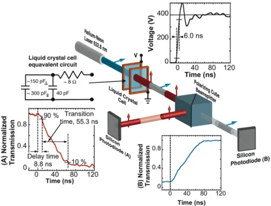
The measurement system consisted of a HeNe laser producing ~ 10 mW of 632 nm polarized light. The light passes through a liquid-crystal cell and into a polarizing-cube-beam splitter. The intensity of each beam was monitored by a fast Si photodiode and recorded by a digital oscilloscope with a 2 ns rise time. Figure 1 shows the experimental setup.
Figure 1. Experimental setup and the definition of delay time and transition time. One of the shortest measured delay times is shown using liquid crystal, PCH5. The cell equivalent circuit (for a cell gap of 5 μm) and the circuitry used to drive the cell are discussed elsewhere4. The output from the Si photodiodes is recorded on a digital oscilloscope,
which is triggered by the rising portion of the voltage applied to the liquid-crystal cell.
Prior to optical switching the liquid-crystal cell is biased with the application of an AC or in some cases a DC voltage, of 1 to 2 V to cause a pretilt of the liquid-crystal directorate which significantly reduces the delay and transition times. This bias has an undesirable side effect of reducing the optical transmission by ~10%. A drive voltage of 10 to 900 V is applied to the liquid crystal cell to change the polarization of light, diverting the light from photodiode A to photodiode B, as shown in Fig. 1. Once the liquid crystal cell is optically switched the drive voltage is removed.
3. SIMPLE MODELING
The transition time of a twisted-nematic liquid-crystal cell for electric fields, >104 V cm-1, is given by eq. 1.5
2 o E γ τ ε ε ≈ Δ (1)
Where E = V/d, the drive voltage, V, across the cell divided by the cell gap, d, γ is the rotational viscosity, Δε is the change of the dielectric constant between the directorate perpendicular and parallel to the electric field.
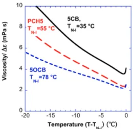
Figures 2 shows the rotational viscosity γ 6 divided by the change in dielectric constant Δε7,8 as a function of
temperature for the three liquid crystals considered here and Figure 3 shows the correlation between the calculated and measured transition times as a function of temperature.
Figure 2. Ratio of the rotational viscosity and dielectric constant change as a function of temperature. The Δε was obtained using the equations in ref 8.
Figure 3. Calculated and measured transition times as a function of temperature for 5CB and 5OCB. PCH5 exhibits a similar agreement. εο=8.85x10⁻¹² F m-1
4. RESULTS
The drive voltage pulse was varied from 20 to 900 V and the delay and transition times were measured as depicted in Figs. 1, 4, 5, and 6. The transitions times monotonically decrease with increasing drive voltage, but the delay times approach a constant value at high electric fields. For 5CB the overall switching time, delay plus transition time, is dominated by the delay time, thus an increase in drive voltage will have a reduced effect on the switching time. However, the delay time for PCH5 continues to decrease with increasing electric field and its switching time is dominated by the transition time for electric fields up to 106 V cm-1.
Fig. 4. Transition times for three liquid crystals as a function of applied electric field. The lines are a least squares fit to the data. The cell gap was 10 μm for 5CB and 5OCB and 5 μm for PCH5.
Fig. 5. Delay time for three liquid crystals as a function of applied electric field. The lines are a general fit to the data.
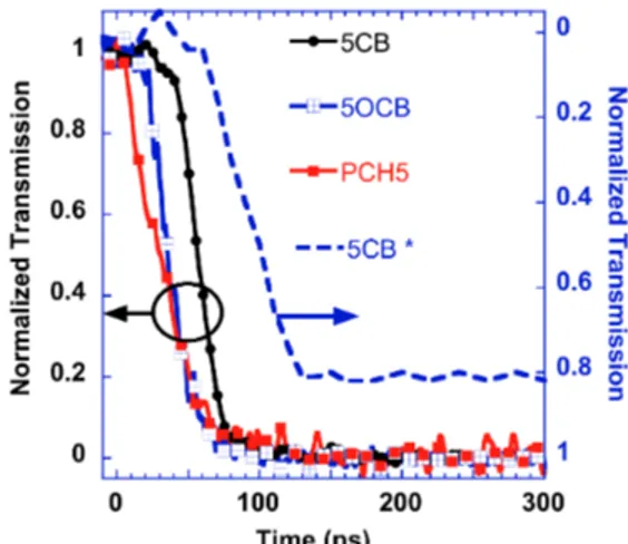
Figure 6 shows the best times obtained for the three liquid crystals tested. The very short delay time for PCH5 is comparable to the rise time of the voltage pulse. The switching time of 5CB is dominated by the delay time for electric fields >5x10⁵ Vcm-1
Figure 6. The best switching times for the three liquid crystals. The electric fields were between 8 and 9 x10⁵ V cm-1. The
cell gap was 10 μm for 5CB and 5OCB and 5 μm for PCH5.
5. DISCUSSION
The application of very large electric fields on liquid crystal cells demonstrates that the liquid crystal transition time is dependent upon the ratio of the rotational viscosity to the change in the dielectric constant, γ /Δε, and varies as ~E-2.
The transition time is limited by the electric field break down ~ 106 V cm-1 for these experiments. At high electric fields
the delay time for 5CB and 5OCB is limited by a property of the liquid crystal. Several groups have correlated the switching time of a liquid crystal with its dielectric response.9,10 The dielectric response time near the T
N-I temperatureis
the shortest for 5OCB, 2.5 ns, followed by PCH5, 6.0 ns, and finally 5CB at 16 ns.11 We are uncertain that our results
can be attributed to the dielectric response time.
Comparison of our result with those of Clark et. al.12 is shown in Figure 7. He uses a larger switching electric field,
1.2x10⁶ V cm-1. The largest electric field that would give consistent results for our set up was 8-9x10⁵ V cm-1. In spite
of this, our delay and transition times were shorter. This may be a result of the bias voltage we used to pretilt the liquid crystal for this report. Clark used a rubbed polymer giving a fixed the pretilt. The polymer reduces the electric field applied to the liquid crystal and might not result in the optimum pretilt.
Fig. 7. The same data as shown in Fig. 6 with the addition of the fastest switching time known in the literature *ref. 12. The incomplete switching, ~ 80%, shown in ref 12 is not understood.13
6. ACKNOWLEDGMENT
The Lincoln Laboratory portion of this work was sponsored by the U. S. Army Natick Soldier Research Development and Engineering Center under Air Force Contract FA8721-05-C-0002. Opinions, interpretations, conclusions, and recommendations are those of the authors, and do not necessarily represent the view of the United States Government.
REFERENCES
[1] "http://www.cordin.com/index.html"
[2] Reich, R. K., Rathman, D. D., O'Mara, D. M., Young, D. J., Loomis, A. H., Osgood, R. M., Murphy, R. A.,
Rose, M., Berger, Tyrell, B. M., Watson, S. A., Ulibarri, M. D., Perry, T., Weber, F., and Robey, H., "Lincoln Laboratory high-speed solid-state imager technology," Proc. SPIE 6279, 62791K (2007).
[3] Lan, J.-H., Kanicki, J., Catalano, A., Keane, J., denBoer, W., and Gu, T., "Patterning of transparent conducting oxide thin films by wet etching for a-Si:H TFT-LCDs," J. Electron Mat. 25(12), 1806-1817 (1996).
[4] Geis, M. W., Molnar, R. J., Turner, G. W., and Lyszczarz., T. M., "30 to 50 ns liquid-crystal optical switches," to be submitted for future publication.
[5] Huh, Il-K., and Kim, Y.-B., "Electro-optical Properties of Liquid Crystal Mixtures Containing
Fluoroisothiocyanated Compounds," Jpn. J. Appl. Phys. 41(11), 6484–6485 (2002).
[6] Bock, F. -J., Kneppe, H., and Schneider, F., "Rotational viscosity of nematic liquid crystals and their shear viscosity under flow alignment," Liquid Crystal 1(3), 239-251(1986).
[7] Simões, M., Simeão, D. S., de Campos, A., and Palangana, A. J., "Corresponding states of nematic
birefringence: an order parameter universality," Philosophical Magazine 87 (33), 5237–5247 (2007).
[8] Simões, M., Simeão, D. S., Domiciano, S. M., and de Campos, A., "Nematic universality," Phys. Lett. A 372, 5346–5351 (2008).
[9] Gu, M., Yin, Y., Shiyanovskii, S. V., and Lavrentovich, O. D., "Effects of dielectric relaxation on the director dynamics of uniaxial nematic liquid crystals," Phys. Rev. E 76, 061702 (2007).
[10] Rathman, M., Hsieh, C.-W., Wang, C.-T., Jian, B.-R., and Lee, W, "Dielectric relaxation dynamics in liquid crystal-dye composites", Dyes and Pigments 84(1), 128-133 (2010).
[11] Urvban, S., Gestblom, B., Kuczyński, W., Pawlusd, S., and Würflinger, A., "Nematic order parameter as
determined from dielectric relaxation data and other methods," Phys. Chem. Chem. Phys. 5, 924–928 (2003).
[12] Takanashi, H., Maclennan, J. E., and Clark, N. A., "Sub 100 Nanosecond Pretilted Planar-to-Homeotropic
Reorientation of Nematic Liquid Crystals under High Electric Field," Jpn. Appl. Phys. 37(5), 2587-2589 (1998).