Advanced Satellite Communication Technology for
Oceanic Air Traffic Control by
Edward H. Kim
Submitted to the Department of Electrical Engineering and Computer Science in Partial Fulfillment of the Requirements for the Degree of
Master of Engineering in Electrical Engineering and Computer Science at the Massachusetts Institute of Technology
May 14, 1998
Copyright © 1998 Edward H. Kim. All rights reserved.
The author hereby grants to M.I.T. permission to reproduce and distribute publicly paper and electronic copies of this thesis
and to grant others the right to do so.
Author
Department of Electrical Engineering and Computer Science
/ . May 14, 1998
Certified by
U Val M. Heinz
MIT Lincoln Laboratory Thesis Supervisor Certified by _
/ Dr. Thomas J. Goblick
MIT Lincoln Laboratory Thesis Supervisor
Certified by _ _
Prof6ssor James K. Roberge Departmeito Electrica and CmputerScience Accepted by
- " Arthur C. Smith Chairman, Department Committee on Graduate Theses
Advanced Satellite Communication Technology
for
Oceanic Air Traffic
Control
by
Edward H. Kim Submitted to the
Department of Electrical Engineering and Computer Science May 14, 1998
In Partial Fulfillment of the Requirements for the Degree of Master of Engineering in Electrical Engineering and Computer Science
ABSTRACT
The current oceanic Air Traffic Control (ATC) system suffers from many inefficiencies, mainly because of infrequent position updates from aircraft. Satellite communication technology shows great promise in solving many of oceanic ATC's problems. In this thesis, we explore available methods for more efficient data transmission in support of oceanic ATC. After examining different types of communication protocols (slotted and random access), multiple access schemes (Time Division Multiple Access and Code Division Multiple Access), bandwidth utilization (spread spectrum and non-spread spectrum), and communication modes (burst and continuous), we separate and identify possible candidate systems, each a unique combination of the previously mentioned communication system concepts, and compare and contrast them in terms of a set of system requirements and criteria deemed critical for oceanic ATC. Throughout the thesis, a special focus is given to CDMA because of its potential capacity advantages. The trade-offs between the candidate systems are considered, and we conclude that TDMA burst systems have a clear advantage over continuous CDMA systems in oceanic ATC. The choice among the various TDMA systems depends on which oceanic ATC criteria are viewed as the most important.
Thesis Supervisor: Val M. Heinz
Title: Technical Staff, MIT Lincoln Laboratory Thesis Supervisor: Dr. Thomas J. Goblick Title: Consultant, MIT Lincoln Laboratory Thesis Supervisor: James K. Roberge
Table of Contents
1. Introduction ... 8
1.1 O verview ... . ... 8
1.2 Basic System Options ... ... 1.3 System Requirements ... ... 9
1.4 Thesis Goal ... 9
2. Current Oceanic Air Traffic Control Procedures ... 11
2.1 Airspace Definitions ... 11
2.2 ATC Communication ... 12
2.3 Shortcomings of Current ATC System ... ... 13
2.4 Inmarsat: A Possible Solution ... 16
2.5 Free Flight ... ... 18
3. Spread Spectrum and CDMA ... 20
3.1 Introduction to Multiple Access and CDMA ... ... ... . 20
3.2 Pseudo-noise (PN) Codes ... 23
3.3 Spread Spectrum Modulation Techniques ... ... ... 24
3.4 Multiple User Access Issues ... ... ... 28
3.4.1 Channel Sharing ... .. .. 28
3.4.2 Continuous vs. Burst Transmission ... 29
3.5 Use of Cellular Telephone Technology for ATC ... 30
4. T D M A ... . ... 36
4.1 Preamble Detection for Burst Mode ... 36
4.2 TDMA Communication Protocol: Slotted vs. Random Access ... 39
4.3 System Architecture Tree ... ... ... 40
5. Comparative Evaluations ... 42
5.1 System Options for ATC Satcom Architecture ... ... 42
5.2 Evaluation Criteria ... 43 5.2.1 Latency ... 44 5.2.2 Spectral Efficiency ... ... 49 5.2.3 Demodulation Complexity... 53 5.2.4 Demodulator Synchronization ... ... 55 5.2.5 Message Security ... 56 5.2.6 RF Interference ... 57
5.2.7 Vulnerability to Multi-User Interference ... 58
5.2.8 Satellite Diversity ... 59
5.2.9 Multipath Interference... 61
6. Evaluation of Candidate Systems and Conclusions ... 64
6.1 Evaluation of Candidate Systems ... 64
6.2 C onclusion ... 68
List of Figures
Figure 2-1. Alaskan airspace ... ... 12
Figure 2-2. New York airspace... 13
Figure 2-3. O akland airspace... ... 14
Figure 2-4. ATC-Pilot communication via ARINC. ... . 15
Figure 2-5. North Atlantic eastbound track structure ... 15
Figure 2-6. Inmarsat satellite fields of view ... ... 17
Figure 3-1. Three multiple access schemes... ... 20
Figure 3-2. A pseudo-noise code sequence ... 22
Figure 3-3. Direct sequence spread spectrum modulation ... ... ... .. 25
Figure 3-4. Frequency hopping spread spectrum modulation ... 26
Figure 3-5. Multiple access decision tree ... ... 29
Figure 3-6. Continuous and burst transmission modes ... ... 30
Figure 3-7. Cellular telephone system. ... 31
Figure 3-8. Air traffic control system ... 31
Figure 3-9. Aircraft multipath signals ... ... ... 33
Figure 3-10. Inmarsat satellite spot beams ... 34
Figure 4-1. A burst message within a time slot ... ... .. . 36
Figure 4-2. Hierarchy of system concepts... . 38
Figure 4-3. Diagram of a fixed preamble detector ... 38
Figure 4-4. Minimum time separation to distinguish two preambles ... 39
Figure 4-5. System architecture tree.. ... 41
Figure 5-1. Statistical latency of the random access protocol ... 45
Figure 5-2. Relationship between the number of users and the probability of collision-free transm ission ... ... 46
Figure 5-3. Overlap of two messages resulting in possible data loss. ... 47
Figure 5-4. Latency of a CW mode message ... ... 48
Figure 5-5. Definition of bandwidth. ... ... 50
Figure 5-6. Diagram of a burst mode receiver. ... 54
Figure 5-7. Diagram of a CW mode receiver... 55
Figure 5-8. Satellite diversity. ... 60
Figure 5-9. Multipath interference in oceanic ATC... 62
List of Tables
Table 3-1. Capacity comparison of three multiple access schemes ... 23
Table 3-2. Communication considerations. ... 32
Table 5-1. Latency of Each System Option ... 49
Table 5-2. Bandwidth of Each System Option ... 53
Table 5-3. Demodulator Complexity of Each System Option ... 55
Table 5-4. Receiver Synchronization of Each System Option ... ... 56
Table 5-5. LPD/LPI of Each System Option ... 57
Table 5-6. RFI Vulnerability of Each System Option ... 58
Table 5-7. MUI Vulnerability of Each System Option... ... 59
Table 5-8. Satellite Diversity of Each System Option ... ... 61
Table 5-9. Multipath Vulnerability of Each System Option... ... 63
Table 6-1. Comparative evaluation of candidate systems ... 65
List of Acronyms
A/C ARINC ARTCC ATC BW CDMA CW DS FAA FANS FDMA FH FSR GEO GES GPS HF ICAO INS LPD/LPI ML MP MUI PG PN RFI SS TDMA TRACON TOA VHF AircraftAeronautical Radio, Inc.
Air Route Traffic Control Center Air Traffic Control
Bandwidth
Code Division Multiple Access Continuous-Wave
Direct Sequence
Federal Aviation Administration Future Air Navigation Systems Frequency Division Multiple Access Frequency Hopping
Feedback Shift Register Geosynchronous Earth Orbit Ground Earth Station
Global Positioning System High Frequency
International Civil Aviation Organization Inertial Navigation System
-Low Probability of Detection / -Low Probability of Intercept Maximum-Length
Multipath
Multi-User Interference Processing Gain Pseudo-Noise
Radio Frequency Interference Spread Spectrum
Time Division Multiple Access Terminal Radar Approach Control Time of Arrival
Acknowledgments
I would first like to thank MIT Lincoln Laboratory and Group 41, in particular, for sponsoring my work and thus making this thesis possible. I would also like to thank my thesis advisor, Professor James K. Roberge, for his support and advice.
Next, I wish to thank Mr. Raymond R. LaFrey, the Associate Division Head of Division 4, for supporting my thesis work. I also thank Dr. Jerry D. Welch, Group Leader of Group 41, for giving me a chance to work in Group 41 for the past 3 years as a 6-A student and supporting me as a Research Assistant for the past year.
My sincerest thanks go to my supervisors, Val Heinz and Dr. Tom Goblick, who always believed in me and helped me through difficult times when getting this thesis completed didn't seem feasible. Working on this thesis with them has been an invaluable experience for my professional and personal growth, and I will never forget all the great lessons I have learned from it.
I also thank the staff at Lincoln Laboratory who helped make my thesis a reality: Dr. William Harman, Randy Wiken, John O'Rourke, Kyle Cochran, Mark Hanson, Ted Roe, Harald Wilhelmsen, Mary Ann Lippert, Tom Petrillo, Chuck Crone, Jim Murphy (thanks for all those rides!), Mary Carey, Gary Hackett, and Kathy Campbell.
Last, but not least, I would like to thank my parents and my sister for their endless support and encouragement. Nothing would have been possible without them!
1. Introduction
1.1
Overview
The Air Traffic Automation Group, Group 41 at Lincoln Laboratory, is investigating new concepts for using satellite communications in reporting aircraft position while the aircraft are flying over the ocean outside of radar coverage. Unlike domestic Air Traffic Control (ATC), which uses radar to track aircraft, oceanic ATC relies on aircraft to periodically, approximately once per hour, transmit their current position to land-based controllers using High Frequency (HF) radio. This is an inefficient system that results in wasted fuel by the aircraft and less efficient use of the airspace. The next-generation approach for reporting aircraft position uses Inmarsat, a constellation of four satellites in geosynchronous orbit. The communication protocol used by the Inmarsat satellites, however, is inefficient for rapidly reporting the positions of many aircraft.
Frequent transmission of aircraft position data to air traffic controllers may allow aircraft to fly oceanic routes more efficiently. Fleet-wide fuel savings on the order of $220M per year may be possible, along with other savings. Instead of using the current communication protocol, other approaches should be explored. One approach uses Code Division Multiple Access (CDMA) combined with spread spectrum broadcast, and another uses Time Division Multiple Access (TDMA) on a standard Inmarsat communications channel. Chapter 2 describes the Inmarsat satellite system in more detail.
1.2 Basic System Options
Chapter 3 provides a high-level introduction to candidate communication protocols and multiple access schemes. One candidate protocol, called random access, is useful because it does not require aircraft to coordinate amongst themselves. There is no need for a master scheduler activity that coordinates communication resources, nor must aircraft synchronize to the same clock. In a system that uses random access coupled with CDMA, aircraft simply broadcast their positions periodically, with each aircraft having been assigned a separate, orthogonal pseudo-noise (PN) code (Chapter 3) to be used for the CDMA encoding. This allows multiple users to transmit at the same time without the problem of user messages being lost when the messages collide, i.e., overlap in time. Chapter 5 includes explanations and discussions of these candidate systems.
A related approach involves sharing a TDMA channel among several aircraft. The channel would remain continuously open, with aircraft assigned to specific time slots within the channel based on their proximity to other aircraft. This approach requires more coordination among the various aircraft but is worthy of further study because of its simplicity and cost-effectiveness.
1.3 System Requirements
We wish to define a set of system requirements before exploring our candidate satcom ATC systems. Comparing and contrasting the candidate systems in terms of the same set of requirements serves to put all the candidate systems on an equal footing. The following are the major system requirements:
* 500 simultaneous aircraft per satellite
* 150-bit messages with 150 bits of forward error correction (FEC) coding
* 30-second position update interval
* 10 bits/sec average data rate per aircraft
* An average of one bit error in 10,000 bits, i.e., bit error rate (BER) = 10- 4
1.4 Thesis Goal
As stated in the overview section, the current oceanic ATC system can be greatly enhanced by using satellite communication technology; we want to explore available methods for more efficient data transmission in support of oceanic ATC. Exactly what type of technology, which communication protocol, multiple access scheme and communication mode should be used, remains to be determined, and this thesis will address each of these issues. The goal of this thesis is to separate and identify a number of possible candidate systems for the current oceanic ATC system, and compare and contrast them in terms of the system requirements we have established in this chapter. The thesis will conduct these comparative evaluations in relation to a set of criteria deemed to be important in oceanic ATC (Chapter 5); the evaluations will be general enough so that a different set of system requirements will simply prompt minor modifications to the thesis results, without having
to make drastic changes or redo the evaluations. Throughout the thesis, a special focus will be given to CDMA, a promising technology that has recently seen great success in civilian applications such as cellular phones. Furthermore, we want to describe any trade-off that might exist between the candidate systems.
The thesis is organized as follows: Chapter 2 will introduce the current oceanic ATC system and its procedures - it discusses oceanic ATC shortcomings and areas of potential improvement. This chapter also introduces a concept called "Free Flight," which is seen as one of the ultimate goals in oceanic ATC, and gives explanations as to how a satcom approach would help achieve this goal.
Chapter 3 gets into the heart of the thesis material; it focuses on the communication issues, and introduces the communication multiple access schemes, protocols, and modes that will be used extensively in the comparative evaluations.
Chapter 4 elaborates on TDMA, and concludes by putting the relevant system concepts together in a system architecture tree, which is a taxonomy tree showing the hierarchy and the relationship of all of the communication concepts.
Chapter 5 justifies the choice of the seven most suitable options from the system architecture tree and performs a comparative evaluation of these seven options. Wherever possible, trade-offs between these options will be discussed and illustrated.
Finally, Chapter 6 identifies the best candidate systems for oceanic ATC among the seven options chosen in Chapter 5.
2. Current Oceanic Air Traffic Control Procedures
2.1 Airspace Definitions
Airspace controlled by the Federal Aviation Administration (FAA) falls into three major categories: domestic en route, terminal area and oceanic. The means for tracking aircraft, i.e., surveillance, and communication, vary between each category. This leads to differences in how aircraft are separated to maintain safety.
Most areas of the United States are covered by en route airspace. Radars with a 12-second sweep period continuously monitor aircraft movement, while pilots and controllers communicate instantly using VHF (Very High Frequency) radio. Aircraft at the same altitude are allowed to pass within five nautical miles (nmi) of each other, but if they will pass closer than that, altitude separation must be established. A separation of 1000 feet is adequate below 29,000 feet, but above that altitude a 2000-foot separation must be maintained.
Many busy airports make use of a Terminal Radar Approach Control (TRACON) facility to help organize the traffic flow for efficient use of the runways. A dedicated radar with a five second sweep period allows smaller separations than in en route airspace.
The United States is responsible for operating large areas of oceanic airspace from three oceanic ATC facilities. The Anchorage, Alaska facility is responsible for all aircraft flying in and around Alaska, and relies on radar to provide position data for aircraft in most of that airspace. There is a gap in radar coverage in the airspace leading toward the Far East, and oceanic separation rules apply in that region. Figure 2-1 shows the airspace controlled by Alaska (dashed lines denote radar coverage).
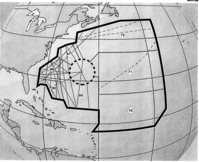
The New York Air Route Traffic Control Center (ARTCC), located in Ronkonkoma (Long Island), New York, is responsible for oceanic airspace in the western part of the North Atlantic (approximately 3 million square miles), as shown in Figure 2-2. Most of this airspace lacks radar coverage, except for an area around Bermuda. The United States Navy used to operate the Bermuda radar, but as part of the military downsizing they have turned responsibility for that radar over to the FAA. Radar data is transferred by telephone line from Bermuda to New York Center for use by air traffic controllers.
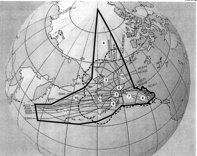
The Oakland Air Traffic Control Center located in Fremont, California (south of San Francisco) is responsible for most of the North Pacific airspace (see Figure 2-3). Except for radar coverage around the Hawaiian Islands and Guam, this airspace is operated
entirely under oceanic separation rules. Oakland Center is responsible for over 20 million square miles of airspace, nearly 10% of the Earth's surface.
24*ALLb7
Figure 2-1. Alaskan airspace.
2.2 ATC Communication
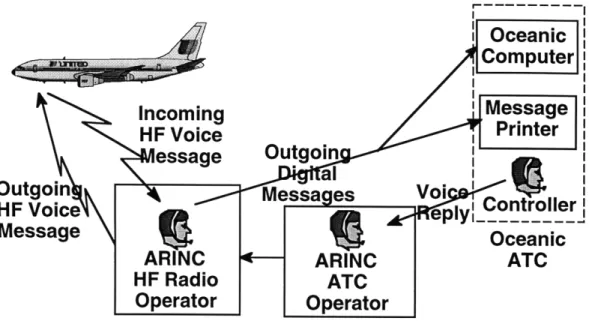
Pilots and controllers must communicate using HF (High Frequency) radio, since line-of-sight VHF radio communication is not possible over the ocean. VHF communication is possible around most of Alaska, as well as the islands of Hawaii, Guam, and Bermuda. A non-profit company called ARINC (Aeronautical Radio, Inc.) is responsible for handling the actual HF communications between pilots and air traffic controllers. For example, when a pilot wants to climb to a higher altitude, they make that request to the ARINC HF Radio Operator. If the operator is busy talking with other aircraft, the pilot must wait their turn. The operator takes the pilot's request and logs it into the ARINC Message Data Base, and then relays it via redundant communication channels to the air traffic controllers. The controller, who is also responsible for many aircraft, must
deal with the request as time permits. Once the controller determines what to do, the decision is relayed by voice back to the ARINC ATC Operator. This operator accesses the data base to retrieve the original request, appends the reply to it, and sends the package back to the ARINC HF Radio Operator, who relays the reply to the pilot. Several minutes can elapse while this entire process unfolds (see Figure 2-4).
Sht6b4B
Figure 2-2. New York airspace.
2.3 Shortcomings of Current ATC System
Oceanic travel today is characterized by a track structure which is set up twice daily to take advantage of, or avoid, the prevailing winds. Aircraft are separated procedurally by assigning them to specific tracks at specific altitudes, and separating the tracks so that aircraft are unlikely to drift onto a neighboring track. No radar coverage is provided over the ocean, therefore large separations are established between aircraft as they begin their flights. These large separations help insure that aircraft do not accidentally collide during the course of their journey. The inertial navigation systems (INS) that aircraft use to
determine their position "drift" approximately one nautical mile per hour over the ocean, because there are no fixed, ground-based radio beacons available to update the INS. Oceanic travel takes many hours to complete, because of the large distances that must be traveled. For each hour of flight, the distance between an aircraft's actual position, and the INS estimated position, will grow by about one nautical mile. Oceanic tracks are separated horizontally to accommodate this drift rate, and aircraft are metered onto each track to provide adequate along-track separation. A typical North Atlantic eastbound track structure is shown in Figure 2-5.
Figure 2-3. Oakland airspace.
The emphasis on safety is clearly justified, but this rigid, procedural approach to oceanic ATC forces aircraft to fly long distances at inefficient altitudes, which wastes fuel. This ATC system has evolved around the limitations of HF radio. The FAA and airlines currently pay over $40 million per year to maintain the HF radio system used to control oceanic aircraft flying in the western Atlantic and the Pacific.
Oceanic
Computer
aIncoming
Message
HF Voice
Printer
essage
Outgoin
Outgoin
IVoi
Otgo"
Messa
es
o
HF Voiceply
MessageOceanc
ARINC
ARINC
ATC
HF Radio
ATC
Operator
Operator
Figure 2-4. ATC-Pilot communication via ARINC.
312524-6B8 700 N 50°N 30ON 900W 60°W 30oW 00 Longitude
2.4 Inmarsat: A Possible Solution
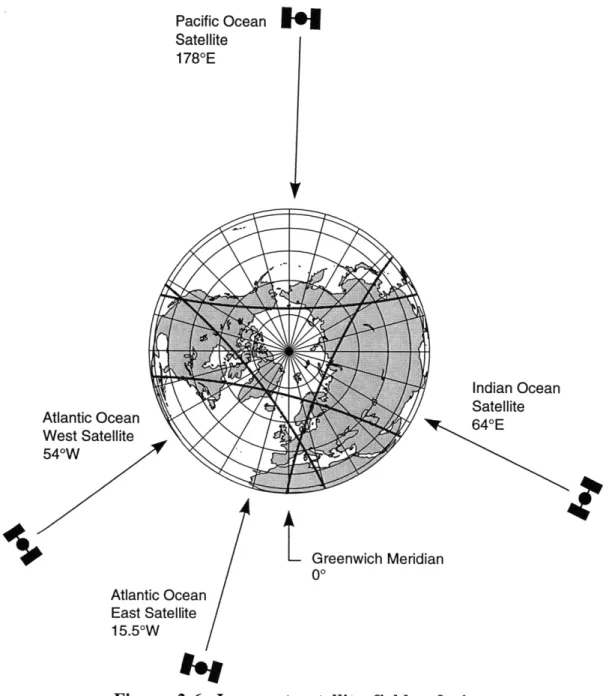
Inmarsat is an international consortium of over 80 countries that operates a constellation of four communication satellites in geosynchronous orbit. The satellites are spaced around the Earth so that they can provide overlapping coverage of the ocean areas up to a latitude of around 70 degrees. Inmarsat recently changed its name from the International Maritime Satellite Organization to the International Mobile Satellite Organization to reflect its intention to compete against Iridium, GlobalStar, and other systems that will offer communication services to mobile users. However, the Inmarsat acronym is so well known that it was decided not to change it.
Inmarsat, whose U.S. signatory is Comsat, has recently launched their third generation of satellites into orbit to replace the second generation equipment. These satellites utilize spot beams to achieve a higher communication capacity by frequency reuse. In order to maintain a minimum of 100 elevation between the satellite and the horizon,
aircraft communicating through Inmarsat must be flying within ± 700 latitude, and ± 700 in longitude from the satellite's longitudinal position. The fields of view of these satellites are shown in Figure 2-6 (Note: distances between Earth and the satellites are not to scale).
Communication between satellites and ground stations is conducted at C-band (4.19 - 6.43 GHz), while L-band (1.53 - 1.64 GHz) is used between the satellite and mobile user (ship or aircraft). Over 20,000 ship operators use Inmarsat as an alternative to HF radio, and over 1500 aircraft are also equipped to communicate using Inmarsat satellites.
Satellites provide an alternative to HF radio for ATC-pilot communications. Aircraft could automatically determine their position using Global Positioning System (GPS) satellites, and relay this data via Inmarsat for display on controller's computer screens. This concept of utilizing satellites for air traffic control is called "FANS-1," with "FANS" being an acronym for Future Air Navigation Systems, and "1" signifying that this is an initial effort. FANS is the result of a collaborative effort led by ICAO, the International Civil Aviation Organization, which seeks to promote worldwide standardization of air traffic control.
The FANS-1 system is designed around standard Inmarsat voice and data communication protocols. Voice circuits are allocated by a request channel: this is a pre-defined frequency that is available to all users, and is accessed using a slotted Aloha
protocol. Voice circuits can take tens of seconds to set up, and they operate at 10.5 Kbps. Data services can be established at slower data rates of 600, 1200 and 2400 bps, and use either a low or high-gain antenna, depending on the data rate. Packet transmission times can range into the tens of seconds.
312524-58 Pacific Ocean Satellite 1780E Atlantic Ocean West Satellite 540W
I.'
Indian Ocean Satellite 640Et
Greenwich Meridian 00 Atlantic Ocean East Satellite 15.50WVoice circuits require the use of a high-gain (phased array) antenna mounted on the top of the aircraft fuselage. These antennas can support from 2 to 6 simultaneous telephone conversations depending on the equipment complexity, thus making satellite voice service available to both pilots and passengers. The satellite ground station connects the mobile user to the public switched telephone network: pilots can talk with air traffic controllers, and passengers can talk with their office, home, etc. Once a voice channel has been set up between an aircraft and a ground station, it remains active until either party hangs up.
High-gain antennas and their accompanying electronics are costly to install and maintain. Unless the equipment is installed during aircraft construction, it is necessary to take the aircraft out of revenue service for several days while installation occurs. The equipment cost alone is several hundred thousand dollars per aircraft, with the exact price dependent on the number of data and voice channels desired.
To recover the cost of installing and maintaining the satellite communication (satcom) equipment, airlines typically charge their passengers $8/minute for telephone calls. The airline keeps about one third of this, and the remainder goes to Inmarsat for the satellite and ground station services.
2.5 Free Flight
Without more frequent position data, ATC will be reluctant to let aircraft operate with reduced separation distances. Instead, aircraft will be kept on a track system, and will be forced to fly long distances at inefficient altitudes. However, airlines want to operate their aircraft economically, and their approach for doing this is called "Free Flight." Under this proposal, airlines would be free to fly any route or altitude they desire, with ATC only monitoring the situation to help resolve conflicts. This implies tactical control of aircraft instead of the procedural control used now for oceanic flights. Aircraft would fly fuel-efficient cruise-climb profiles that minimize fuel usage. Horizontal separations would be reduced from 50-60 nautical miles down to a few miles to permit better utilization of "best
wind" altitudes.
To make Free Flight happen over the ocean, frequent position reports will be required and satcom must replace HF radio. However, as was discussed earlier in the Inmarsat section, the current FANS-1 system doesn't offer the right kind of communication
protocol. This thesis explores more promising approaches: Time Division Multiple Access (TDMA) and Code Division Multiple Access (CDMA).
3. Spread Spectrum and CDMA
3.1 Introduction to Multiple Access and CDMA
Communication costs are minimized when multiple users are allowed to efficiently share a common communication channel. The three most common methods that exist for accommodating multiple access are Frequency Division Multiple Access (FDMA), Time Division Multiple Access (TDMA), and Code Division Multiple Access (CDMA).
In FDMA, each user is assigned a unique sub-channel within the available frequency band (Figure 3-1). There is no need for synchronization of signals among users since each sub-channel is dedicated exclusively for each user. The receiver has a bank of demodulators, with one demodulator assigned to each sub-channel. The sub-channels are separated by guard-bands in order to prevent signals from interfering with those in other sub-channels. This multiple access scheme is the oldest and the most basic of the three, and is still widely used in satellite communication today for its simplicity. Its main disadvantage is that cost increases linearly with the number of users. Also, even with guard-bands there still can be a substantial amount of sub-channel cross-talk, called intermodulation or RF interference.
312776-1 Frequency Division Multiple Access (FDMA) Time Division Multiple Access (TDMA)
Sub-Channel
I
S Sub-Channel 2 u Sub-Channel 3 Time Code Div ur1) 0 a-L. Figure 3-1. 0 C C C C Time ision Multiple Access (CDMA)Sub-Channel I Sub-Channel 2 Sub-Channel 3
Time
In TDMA, each user is assigned a time slot during which signals are transmitted. A master scheduler arranges the time slot assignment beforehand, and each user is permitted to transmit their signal only during their assigned time slot. As shown in Figure 3-1, the time slots alternate so that the user can repeatedly send out the same information (such as position reports), or send out segments of a longer message. Segmented messages would be recombined at the ground station receiver. In between the time slots are guard-times which accommodate the unavoidable inaccuracies in timing and synchronization of the time slots. TDMA also avoids FDMA's intermodulation problem.
Compared to FDMA and TDMA, CDMA is unique in that the signals are superimposed on top of each other both in time and frequency. Each user is assigned a unique pseudo-random or pseudo-noise (PN) code, which is a binary sequence of ones and zeroes that serves to identify each user and hence distinguish their message from other users. In order for CDMA to work properly, bandwidth expansion of its signals is required, hence the term "spread spectrum."
PN codes play a crucial role in achieving bandwidth expansion. A PN code is used to expand the bandwidth of a signal by phase modulating the original signal according to the value of the bits of the PN code. The portion of the signal in which the carrier phase is made to correspond to a single digit of the PN code is called a "chip." The chipping rate is the number of PN bits used per unit time to change the carrier phase. The chipping rate thus determines the spreading of the spectrum of the original signal (Figure 3-2).
One important parameter in a spread spectrum system is the processing gain:
Tb PG = T
where Tb is the bit time of the signal and T is the chip time of the PN code [10]. Thus, the shorter the chipping time, which means the chipping rate is high, the greater the processing gain. As we shall see, the processing gain plays an essential role in correctly demodulating the signals at the receiver end.
312776-2
Time
-1
Figure 3-2. A pseudo-noise code sequence.
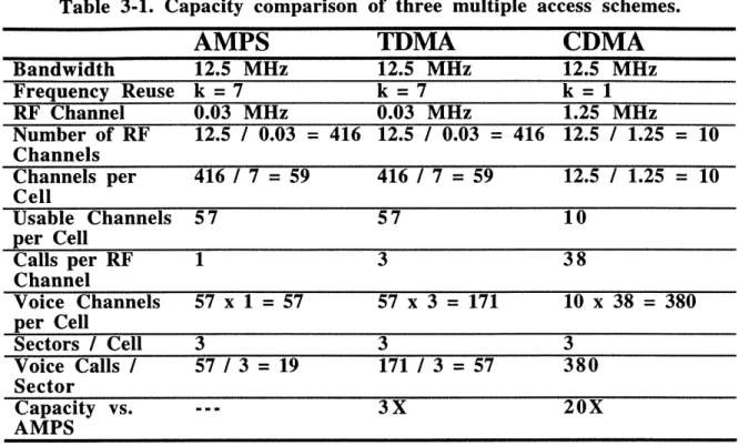
In the past, CDMA systems have been widely used in military applications because of their security and low probability of detection properties. The key advantage, however, that CDMA has over FDMA and TDMA is its potential for higher capacity. This advantage is shown in Table 3-1, which compares AMPS (an FDMA implementation), TDMA and CDMA telephone systems [2]. A typical AMPS system allows 19 telephone calls per sector. TDMA triples this capacity, and CDMA increases the capacity by a factor of 20. Further increases are not possible because of self-interference issues associated with CDMA [8]. Processing gain is used to suppress the multiple-user interference caused by the PN-encoded signals that reside in the same spectrum. Thus, high processing gain is desired, but it is impractical to build a demodulator with a processing gain greater than 104
[19].
Table 3-1 includes frequency reuse constraints, which is why AMPS can accommodate only 19 calls/sector [2].
Table 3-1. Capacity comparison
AMPS
of three multiple access schemes.
TDMA
CDMA
Bandwidth 12.5 MHz 12.5 MHz 12.5 MHz Frequency Reuse k =7 k = 7 k = 1 RF Channel 0.03 MHz 0.03 MHz 1.25 MHz Number of RF 12.5 / 0.03 = 416 12.5 / 0.03 = 416 12.5 / 1.25 = 10 Channels Channels per 416 / 7 = 59 416 / 7 = 59 12.5 / 1.25 = 10 Cell Usable Channels 57 57 10 per Cell Calls per RF 1 3 38 Channel Voice Channels 57 x 1 = 57 57 x 3 = 171 10 x 38 = 380 per Cell Sectors / Cell 3 3 3 Voice Calls / 57 / 3 = 19 171 / 3 = 57 380 Sector Capacity vs. --- 3X 20X AMPS 3.2 Pseudo-noise (PN) CodesA PN code consists of a series of bits. The total number of possible PN codes for a series of "n" bits is 2". In practice, however, only a small subset of the total number of possible codes can be used for CDMA communication. This is because the codes must exhibit certain features in order to be useful for CDMA. The codes must:
* be easy to generate * have a long period
* have desireable randomness properties (autocorrelation and cross-correlation)
PN codes must be easy to generate because the ground station receiver needs to generate a local PN code in order to demodulate the signal. A long period (i.e., a large number of bits) is needed to maximize the total possible number of PN codes, so that a reasonably-sized family of codes with suitable properties (as described below) can be extracted. For security reasons, it should not be possible to reconstruct an entire PN code from a short code segment [14].
The ideal autocorrelation would be an impulse function centered around zero. This helps the local PN code synchronize and lock on the incoming signal, and also helps resist multipath interference [14].
Illll I
User separation is achieved by correlating the received signal with the appropriate locally-generated PN code. Therefore, zero (orthogonal) or low (non-orthogonal) cross-correlation is required to insure that the receiver correctly associates the locally generated PN code with the proper user.
One popular way of generating PN code sequences is by the use of feedback shift registers (FSRs) [10]. Because a desired property of a PN code is a long period, a popular sequence generated by FSRs is the maximum-length (ML) FSR code. The period of a ML code is given by 21 - 1, where 1 is the number of shift registers used. For ML codes of
length L, the autocorrelation function, R(,), can be shown to be
(1 T = 0, L,2L,... otherwise
The number of ML FSR codes is limited. Additional codes can be generated by adding two different ML codes by modulo-2 addition. The resulting codes are called Gold codes, arguably the most popular codes in use today [14]. Note that Gold codes are nonlinear in nature which makes analysis of these codes difficult.
An important parameter involving PN codes is the ratio of the maximum cross-correlation coefficient and the autocross-correlation coefficient [14]. This ratio is important because it is a measure of how well a PN code can reject interference from other users' codes; the smaller the ratio, the better is the rejection of interfering users. For Gold codes, the maximum cross-correlation coefficient is given by
K2 (n+1) 2 + 1
K 2(n+2) /2 + 1
where n is even. The maximum auto-correlation coefficient of Gold codes is the length of the code. Hence, for a Gold code generated by a 5-stage FSR, the ratio comes out to be 0.29, compared to 0.23 for the corresponding ML code and 0.43 for a corresponding non-ML code [14].
3.3 Spread Spectrum Modulation Techniques
CDMA must use one of the following spread spectrum modulation techniques to achieve bandwidth expansion. It is important, however, to note that the use of spread spectrum does not necessarily imply CDMA. The defining characteristic of a CDMA
system is "code division," i.e., the system uses codes to separate the users, and this need for codes requires spread spectrum.
Direct Sequence (DS)
In the DS spread spectrum modulation, the data sequence is directly multiplied by a pseudo-noise (PN) code sequence, and the resulting signal is transmitted (Figure 3-3). The frequency of the PN code, which consists of chips that undergo rapid phase changes, is greater than that of the data sequence. Since the chipping rate is approximately equal to the bandwidth, the transmitted signal occupies more bandwidth than does the original data sequence, hence the term spread spectrum. At the receiving end, the data signal is extracted by multiplying the received signal by a locally generated PN code sequence which is identical to the original PN code. The operations involved in Direct Sequence are thus relatively simple - a simple multiplication of the signal with a PN code is all that is required
- which makes it a cost-effective option. Its simplicity and cost-effectiveness have made DS a huge success in the civilian cellular telephony industry, as evidenced by Qualcomm's DS-CDMA cellular phone system.
312T6-3B
1 1
ime Time
Signal I Pseudo-Noise Code
Time
-l
Spread Signal
Frequency Hopping (FH)
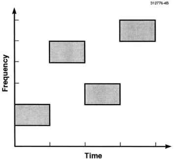
The data signal is modulated with a carrier frequency which is not constant but is hopped to different frequencies; the hopping pattern is dictated by the PN code (Figure 3-4). Thus, at any one time, the modulated signal occupies a small portion of the frequency spectrum. FH is spread spectrum since the hop-set, which is the collective set of all the frequencies over which the signal is hopped, ranges over the entire channel bandwidth. There are two types of FH, fast and slow, depending on the rapidity of the frequency change. In fast FH, one bit is transmitted in several hops, whereas in slow FH, one or more bits are encoded in a single hop.
One advantage of FH is in the exponential increase of orthogonal code users that can be achieved with increasing chipping rate [5]. This is superior to DS which has only a linear increase of capacity with increasing chipping rate. The exponential factor in capacity of FH can be seen in the following expression for K, the capacity factor:
K < 2R I Rh
where Rcis the chipping rate and Rh is the hopping rate.
312776-48
I -.
Figure 3-4. Frequency
Time
hopping spread spectrum modulation.
However, there are several disadvantages for FH, and that is perhaps why the vast majority of current CDMA systems, at least for civil applications, use the Direct Sequence method. One disadvantage of FH is that it puts a severe constraint on the frequency
hopping generators, which must be accurate enough to ensure that there are no errors in decoding. Also, frequency resolution of generators must be quite exact; even a slight deviation from the frequency set can cause errors in decoding. Moreover, the hopping time, which is the time needed for the hopper to make a jump from one frequency to the next, needs to be very short, or otherwise there would be an energy degradation in
decoding, given by the expression, (1- _E)2 , where E is the hop settling time and To is
the hopping period [5].
Time Hopping (TH)
This approach is similar to FH, but in TH the PN code dictates the time intervals of bursts of the data signal to be transmitted within a frame; the time axis is divided into frames which are, in turn, divided into a certain number of yet smaller time intervals called slots. The transmission occupies the entire frequency spectrum. With synchronization among the users, TH becomes straight TDMA if the PN code doesn't allow more than one user per slot at any one time. As we shall see later, TH is a form of burst mode communication which will provide another set of options for the satcom system.
Hybrid Modulation
This consists of different combinations of the methods mentioned above, for example, a combined DS and FH system. This option is excellent for complementing the advantages of each method, but hardware can get very complex with hybrid modulation.
Looking at the aforementioned spread spectrum modulation techniques, we have decided to explore the Direct Sequence method further, mainly because of its simple yet reliable nature and cost-effectiveness, which are two important qualities for any ATC system. When considering FH as an option for the satcom system, there is a concern of complexity of accurate frequency generators and the need to keep them synchronized for multiple users.
Section 3.2 introduced the concepts of orthogonal and non-orthogonal CDMA. Orthogonal CDMA means that the PN codes have zero cross-correlation with each other. This method of CDMA requires strict synchronization between the received code and the local code to ensure proper demodulation; synchronization is essential for orthogonal
CDMA since even a slight error in synchronization would misalign the chips of the local and the incoming signals and thus lose some of the received energy. An advantage of orthogonal CDMA is that with proper demodulation, other user's signals are orthogonal to the desired signal, which insures correct decoding. For the orthogonal system, capacity increases linearly with satellite power and RF bandwidth [5].
Non-orthogonal CDMA uses codes with low, but not zero, cross-correlation, and has less stringent synchronization requirements. A disadvantage of the non-orthogonal method is that it needs higher power levels to achieve the same level of performance as an orthogonal system [5]. Also, this code family would be hard to construct for a large number of users, and therefore is not of interest to this thesis.
3.4 Multiple User Access Issues
Allowing multiple users to access a communications channel is not simply a matter of choosing a multiple access scheme, such as FDMA, TDMA or CDMA. This section examines several issues that must be addressed when choosing a multiple access approach.
3.4.1 Channel Sharing
Figure 3-5 shows an approach for addressing multiple access issues. The first decision that must be made is whether to dedicate a satellite transponder channel for ATC communication, or instead to allow ATC communication to share transponder bandwidth with other users. These decisions have technical, economic and political implications.
A dedicated channel is attractive because it can be sized to support the expected communication traffic load. If the expected load can be accurately estimated, channel bandwidth can be minimized, which helps reduce costs. Ensuring that the bandwidth is protected for aviation use only, so that position reports and other data can be transmitted without interference, is important from a safety standpoint. A dedicated channel could be operated in either a spread spectrum or non-spread spectrum mode.
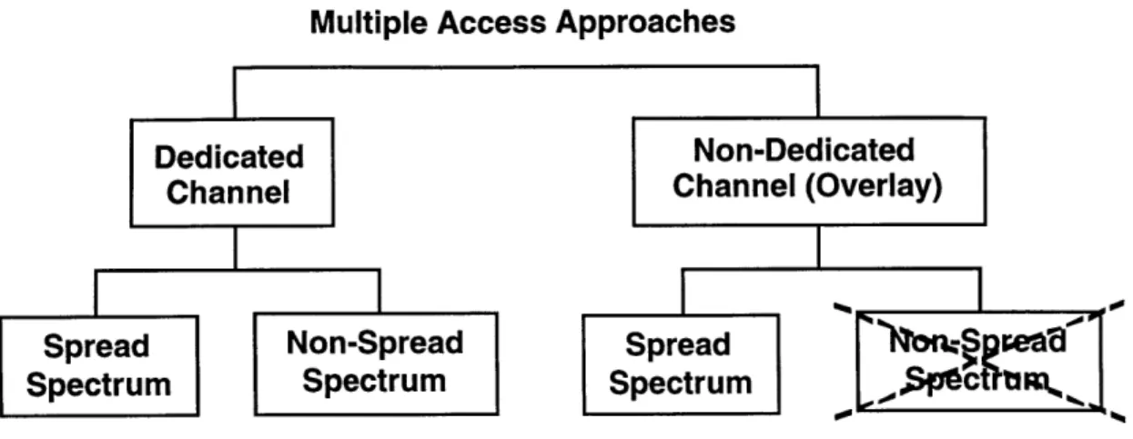
Multiple Access Approaches
Figure 3-5. Multiple access decision tree.
A dedicated ATC channel will probably require 20 -50 KHz of bandwidth. This is only a small portion of the 10 MHz aeronautical L-Band bandwidth available on an Inmarsat-II satellite. This bandwidth is currently shared among users of aeronautical voice and data services.
A non-dedicated channel approach would overlay ATC communications on the existing Inmarsat voice and data services. This approach is only feasible if spread spectrum technology is used, because 1) ATC communication must not interfere with the other services, and 2) processing gain is needed to combat the "interference" generated by those other users, to ensure that ATC communication succeeds. The cost of such a service would have to be negotiated with Inmarsat, since it falls outside their existing set of standard services.
3.4.2 Continuous vs. Burst Transmission
Earlier, Figure 3-5 showed three feasible multiple access approaches:
* Dedicated Channel, Spread Spectrum * Dedicated Channel, Non-Spread Spectrum * Non-Dedicated Channel, Spread Spectrum
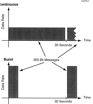
Each of these communication modes may be further subdivided into two types of transmission: continuous and burst. These transmission types are illustrated in Figure 3-6. Continuous transmission uses a low instantaneous data rate, while burst uses a high rate. In the figure, continuous transmission requires almost 30 seconds in which to transmit the
message (long latency), while bursts require much less time (short latency). Continuous transmission is sometimes referred to as "continuous wave," or CW.
312776-7
Continuous
ca
Burst 300 Bit Messages
Time 30 Seconds
Figure 3-6. Continuous and burst transmission modes.
3.5 Use of Cellular Telephone Technology for ATC
A popular use for CDMA technology is in cellular telephone systems. Qualcomm, the world leader in CDMA cellular systems, has delivered over one million handsets to consumers worldwide. It is reasonable to ask if cellular telephone systems offer an approach that might also be useful for oceanic ATC. Figures 3-7 and 3-8 illustrate the cellular and ATC environments, respectively.
In a cellular telephone system, users communicate via handsets to base stations located throughout the service area. Once a link is established, communication is continuous until either party hangs up. If a similar approach is used for ATC, the aircraft population would communicate via satellite with the ATC facility. Continuous communication would exist throughout the oceanic portion of the flight.
312776-5B
9.6 kbps
20-30 Users/Sector
Figure 3-7. Cellular telephone system.
Although these two systems are similar on a conceptual level, there are important differences. Several important communication considerations are listed in Table 3-2, along with a description of how these differ between cellular and ATC.
312T6-6B
300-Bit Message Every 30 sec
500 Aircraft
Figure 3-8. Air traffic control system.
Shadowing occurs when an object, such as a building, obscures the direct line of sight between a user and a base station. A related problem is multipath interference, where the signal can bounce off a building, creating multiple signal paths between the user and the base station. The different signals can combine constructively or destructively at the destination. Destructive interference would require that the message be retransmitted.
Table 3-2. Communication considerations.
Considerations
Shadowing Multipath interference Hand-offCellular
Causes multipath interference and signal loss.
Significant in urban environments. Happens frequently.
ATC
Not a factor.Only one bounce off surface of ocean.
Not a factor for GEO global beam; minor factor for spot beam. Would happen
frequently with LEO satellite. Power control Real-time control (20 ms Non real-time control (minutes).
frame).
Doppler effects Important factor. Minor factor for GEO satellites; important factor for LEO satellites.
Link budget Low power handset, small High power transmitter, large distances, omni antenna. distances, directional antenna.
PN codes Need -32 unique Each aircraft requires a unique
codes/sector. code (500 - 1000 codes). Message characteristics Short-term, continuous, Long-term, repetitive (favors
highly variable, burst over continuous).
Shadowing and multipath interference are problems for cellular users in dense urban environments, but are not problems for ATC. Satellite antennas for aircraft are mounted on the top of the aircraft fuselage, and generally have an unobstructed view of the satellite. The aircraft tail may provide some shadowing, but only at extreme (low elevation) view angles. If the aircraft is operating at an extreme northern or southern latitude, it is possible that it will experience a single multipath bounce off the ocean surface, as illustrated in Figure 3-9. However, since the unwanted signal will travel at a negative elevation angle as viewed from the aircraft, this situation can usually be avoided by proper antenna pattern design.
312776-21
#01 (Delayed)
Path #2 ,
Ocean
Figure 3-9. Aircraft multipath signals.
Hand-off for cellular telephone users is done when a user moves between sectors and needs to switch from one base station to another. In order to successfully execute a hand-off, the base stations need to carefully monitor the power level of each user to determine which sector they are in. ATC users have the option of using either a global beam, or one of several spot beams. Figure 3-10 shows the Earth as viewed from the geosynchronous Earth orbit (GEO) Inmarsat satellite located in the Atlantic-East orbital position (150 West longitude). The global beam allows communication from roughly ±
700 latitude, and ± 700 in longitude from the orbital longitude. Spot beams, shown in the figure as ellipses, provide additional power to areas of high traffic. If aircraft use the global beam, hand-off is not an issue. If aircraft use the spot beams, hand-off may be necessary, but it will occur on a scale of hours (vs. minutes for cellular telephone users). For low Earth orbit (LEO) satellites such as Iridium or Globalstar, hand-off would be similar to a cellular system because an individual satellite would be within view of an aircraft for only a few minutes.
Power control is done in a much more tightly coupled manner for cellular telephones than would be needed for ATC. Since the distance between a mobile user and a cellular telephone base station can vary quickly, Qualcomm uses a 20 msec cycle for adjusting power levels, so that each user's power at the base station is approximately equal [17]. For an ATC application, the distance between an aircraft and the satellite does not vary rapidly, simply because of the large distance involved (-20,000 nautical miles). Power control would be needed every few minutes. For similar reasons, Doppler shifts are more of an issue for cellular users than they would be for a satellite-based ATC system.
Link budgets are another area of difference. Cellular telephone handsets transmit in the milliwatt to a few watts range, while aircraft transmitters use tens of watts. Cellular base stations have essentially unlimited power available, while satellites are limited by the efficiency of their solar cells and batteries. Satellite systems operate over distances thousands of times farther than cellular systems, and can make use of directional antennas (vs. cellular omni antennas). All of these factors greatly affect link budget calculations.
N Centr
NW /
Figure 3-10. Inmarsat satellite spot beams.
For a continuous communication system, the number of pseudo-noise (PN) codes that are needed is the same as the number of users. The user population is divided among cells and sectors (3 sectors / cell) in the telephone system, and since self-interference limits the number of users that can be serviced in a given sector, only about 32 PN codes are required [7]. An ATC system would require as many codes as there are aircraft (500
-1000), unless spot beams are used, in which case frequency reuse between spot beams would reduce the number of codes.
Finally, there are many differences in message characteristics. Cellular conversations generally last only a few minutes, while oceanic flights travel for several hours. Conversations vary widely in content, whereas ATC messages repeatedly report aircraft ID, position, altitude and time. If ATC messaging were done on a continuous basis, like cellular, this would increase message latency. However, increased latency increases a controller's uncertainty about aircraft location, which would result in an undesirable increase in aircraft separation requirements.
Even though the cellular telephone communication technology, with CW CDMA, does not appear to be compatible with the ATC application, it will be evaluated later in Chapter 5.
4. TDMA
In this chapter, we elaborate on one of the multiple access schemes, TDMA, which was briefly discussed in Chapter 3. At the end of the chapter, we present a system architecture tree that brings together and establishes the hierarchy of the concepts presented in Chapters 3 and 4.
4.1 Preamble Detection for Burst Mode
Unlike the continuous mode of communication, which uses continuous synchronization-tracking (synch-tracking) of the incoming messages, the burst mode requires a mechanism that can detect the arrival of a message - without mistakenly recognizing a non-message as a message - and properly demodulate the message. Such a mechanism must make use of a message preamble, which is a header-like portion of the message that is used to detect the arrival of a message and establish its time of arrival (TOA), and provide the demodulator with bit timing information.
312776-8
i-rame
Slot # Slot #2 Slot #N
- Preamble Data Block
CR
BTR
UW
Slot Time
CR = Carrier Recovery BTR = Bit-timing Recovery
UW = Unique Word
Figure 4-1. A burst message within a time slot.
Figure 4-1 shows a message within a time slot which is divided into its preamble and data parts [5]. The number of bits allocated for the preamble should be shorter than for the actual data block. The preamble efficiency, or overhead, is defined as:
Guard Time
Number of preamble symbols 7=P Total number of symbols per slot
This parameter gives a measure of the efficient use of bits for a preamble, and is around 10 percent or less for typical TDMA systems [5].
The preamble detector is a matched filter that detects the preamble of an incoming message. A matched filter, also called a correlator, is the optimum detector for detecting pulses that have been corrupted by channel noise, and minimizes the effects of noise and enhances detection of the original pulse signal [10]; the name "matched" comes from the fact that the impulse response is the time-reversed and delayed version of the pulse signal,
i.e.,
hopt( t) = kg(T - t)
where g(T - t) is the pulse waveform with the delay T, and k is an arbitrary constant. When a preamble is detected, the matched filter produces a big "spike" that exceeds a preset threshold value, signaling the arrival of a preamble. The time of arrival of the preamble is then estimated from the preamble spike time, and is used to synchronize the demodulation process. After the preamble detection phase, the data stream is sent to the appropriate demodulator to be decoded.
In spread spectrum burst systems, the preamble detector must have the ability to detect preambles that have been decoded with PN codes and thus resemble noise. Two options exist for spread spectrum burst systems: fixed preamble detection and programmable preamble detection (Figure 4-2).
314296-1
Spread Spectrum
Continuous Burst
Fixed Preamble Prog
Pr
rammable eamble
Figure 4-2. Hierarchy of system concepts.
In a fixed preamble system, only one PN code is used for all time. The preamble detector is set up with a PN code that allows it to detect PN-coded preambles. The PN code is used as a spreading mechanism to mitigate the effects of interfering signals, e.g., for an overlay channel with users of other type of services, or in a multiple access mechanism (Figure 4-3). 312776-10 PN Code Key
A AA
Preambles Preamble Detector DemodulatorFigure 4-3. Diagram of a fixed preamble detector.
In a programmable preamble system, a number of PN codes are used by the system, each being valid only in a specific time interval. A single, programmable, preamble detector that can be configured with a different PN code for every time period, is used to process all the preambles. Hence, complexity is an issue for programmable preambles because not only must the preamble detector be able to change the PN code, but all of the users must change their PN code as well in each time period. Thus, during any one time period, programmable preamble detection effectively becomes fixed preamble detection, with the next time period simply using a different PN code for all of the users.
If some messages are deemed more important than others, one preamble detector can be dedicated for that particular message or type of messages only, with other detectors being used for other types of messages. Such use of multiple preamble detectors effectively creates additional channels that can improve the system's spectral efficiency.
4.2 TDMA Communication Protocol: Slotted vs. Random Access
In a burst mode system, two or more preambles may collide, or arrive at the receiver at the same time. Unless a way to distinguish these preambles exists, all of the overlapping preambles would go undetected and the subsequent data streams would get lost. With partially overlapped preambles, however, it is still possible to distinguish one message from another. This separation in time, however, must be at least twice the chip duration, which is the minimum time that the preamble detector needs to resume its search for preambles after having detected the first one (Figure 4-4). The chip duration of a signal is a critical factor in preamble detection. The chip duration can be made shorter to reduce the chance of collisions, which is why spread spectrum offers a big advantage in this regard. More discussion on this point appears in the multipath interference section of the comparative evaluation section (Chapter 5).
314298-2
At > 2Tchip
2Tchp
Time
Figure 4-4. Minimum time separation to distinguish two preambles.
Two methods are used to cope with this collision problem: slotted and random access, which are two protocols for time sharing a communication channel. These protocols apply only to TDMA systems since in a CW system, message collisions are occurring all the time at the receiver. In the slotted protocol, each burst is sent in a time slot; only one user is permitted to transmit during any one time slot. In the random access protocol, the bursts are sent randomly, i.e., at any time a user wishes to transmit, without
any coordination amongst the users. If the message is received without any collision, then the user gets an acknowledgment of successful transmission from the receiver. If a collision occurs, the acknowledgment is not obtained and the user must re-transmit the message after a certain wait period that is randomized so as to minimize the chances of having a second collision with the same user. The ALOHA system, developed in Hawaii in the early 1970's, is an example of a random access system [9]. A hybrid combination of random access and slotted, the slotted Aloha system, also exists and is used extensively with Inmarsat satellites.
4.3 System Architecture Tree
Figure 4-5 shows a taxonomy tree that brings together all of the system concepts introduced thus far: dedicated vs. shared channels (channel sharing), spread spectrum vs. non-spread spectrum (bandwidth utilization), burst vs. CW (mode of communication), slotted vs. random access (communication protocol), and fixed vs. programmable preamble detection (PN code usage). The use of a shared channel requires spread spectrum, and thus no further branches are connected to the Shared/Non-SS node. The Dedicated/Non-SS/CW leaf node is FDMA. In Chapter 5, we will explore the rest of the leaf nodes by conducting a comparative evaluation study of them.
314298-4
#3: Communication Mode
Communication Protocol
-4-- #.5: PN Code
Usage
Figure 4-5. System architecture tree.
CW: Continuous
R.A.: Random Access
F.P.: Fixed Preamble Detection
P.P.: Programmable Preamble detection
5. Comparative Evaluations
In this chapter, we take a set of system alternatives from the system taxonomy tree, and define seven different system options that will be considered for oceanic ATC. The evaluation methodology is first introduced. The evaluations are performed with respect to a set of criteria that are critical in oceanic ATC.
5.1 System Options for ATC Satcom Architecture
The system architecture tree, which was presented in Chapter 4, deals with the following issues, each constituting a layer of the tree. We have already indicated preferences for some of these issues that are best suited to the needs and requirements for the ATC system:
* Channel sharing (overlay vs. dedicated channels): both overlay and dedicated channels are explored, even though overlaying would be hard to implement with existing satellite communication systems, such as Inmarsat, because of practical problems
* Bandwidth utilization (spread spectrum vs. non-spread spectrum): spread spectrum preferred for potential capacity and LPD/LPI reasons
* Communication mode (burst vs. continuous)
* Communication protocol (slotted vs. random access -for burst mode only)
* PN code usage (fixed vs. programmable preamble -for spread spectrum only)
* Spread spectrum modulation (DS vs. FH): see Chapter 3 -DS preferred
Using these layers, we can define the following seven system configurations for the ATC system:
1) Non-SS -burst -slotted TDMA (no PN codes)
2) Non-SS -burst -random access TDMA (no PN codes) 3) SS -burst -slotted -fixed preamble TDMA (one PN code)
5) SS -burst -random access -fixed preamble TDMA (one PN code)
6) SS -burst -random access -programmable preamble TDMA (multi-PN codes) 7) SS -CW CDMA (multi-PN codes)
5.2 Evaluation Criteria
The candidate systems, i.e., the seven options, will be compared with respect to a number of criteria that are relevant to oceanic ATC. Each evaluation criterion will first be defined and explained in this section. The following parameters are used in all of the comparative evaluations:
* M = number of users = 500 users
* Pm = Probability[500 messages get through with no collision] > 0.9 * T,,te= message update interval = 30 seconds
* Average data rate = 300 bits / 30 sec = 10 bits / sec
* crn = minimum energy-to-noise density for reliable communication = 5 (7 dB)
* ndatabits= number of data bits in message = 150 bits
Snbits/slot,= number of bits per slot = 2 x ndatabits +100 bits = 400 bits (Note: we assume 100 bits of overhead, which include preamble bits)
* Jamming margin (i.e., the amount of intentionallincidental interference that the system must be able to withstand) = 100 (Note: a jamming margin of 100 means that the system should operate reliably with- < 100 at the receiver
P input, where J is jamming power and P is signal power)
The following evaluation criteria will be considered:
* Latency
* Spectral efficiency (total bandwidth)