HAL Id: hal-02298374
https://hal.archives-ouvertes.fr/hal-02298374
Submitted on 26 Sep 2019
HAL is a multi-disciplinary open access
archive for the deposit and dissemination of
sci-entific research documents, whether they are
pub-lished or not. The documents may come from
teaching and research institutions in France or
abroad, or from public or private research centers.
L’archive ouverte pluridisciplinaire HAL, est
destinée au dépôt et à la diffusion de documents
scientifiques de niveau recherche, publiés ou non,
émanant des établissements d’enseignement et de
recherche français ou étrangers, des laboratoires
publics ou privés.
Distributed under a Creative Commons Attribution - NonCommercial - NoDerivatives| 4.0
International License
Toward simplified electrochromic devices using silver as
counter electrode material
Abdelaadim Danine, Laura Manceriu, Cyril Faure, Christine Labrugère,
Nicolas Penin, Anastasia Delattre, Guy Eymin-Petot-Tourtollet, Aline Rougier
To cite this version:
Abdelaadim Danine, Laura Manceriu, Cyril Faure, Christine Labrugère, Nicolas Penin, et al.. Toward
simplified electrochromic devices using silver as counter electrode material. ACS Applied
Materi-als & Interfaces, Washington, D.C. : American Chemical Society, 2019, 11 (37), pp.34030-34038.
�10.1021/acsami.9b12380�. �hal-02298374�
Abdelaadim Danine
, Laura Manceriu
, Cyril Faure
, Christine Labrugère
, Nicolas Penin
, Anastasia
Delattre
†, Guy Eymin-Petot-Tourtollet
†and Aline Rougier
*
CNRS, Univ. Bordeaux, Bx INP, ICMCB UMR 5026, F-33600 Pessac, France PLACAMAT, UMS 3626, CNRS-Université Bordeaux, F-33600 Pessac, France
†CTP, Domaine Universitaire, BP 251, 38044 Grenoble, Cedex 9, France
KEYWORDS. Electrochromic Displays, Silver layer, PEDOT, Device Architecture, Optical modulation,
*: Corresponding author: aline.rougier@icmcb.cnrs.fr
ABSTRACT:
Novel design of electrochromic devices ECDs, known for their ability to modify their optical properties under an applied voltage, based on a minimization of the number of layers is reported. The use of a metallic electrode, playing the role of both the conductive layer as well as the counter electrode allows to simplify the assembly of commonly 5 layers battery type device to 4-layers ECD. Further minimization of the number of layers is achieved by using a conductive and electrochromic material. The novelty of the device configuration is illustrated using poly(3,4-ethylenedioxythiophene) PEDOT based materials as EC layer, lithium based ionic liquid as electrolyte and Ag as counter electrode. Such 4- or 3-layer ECD deposited on paper substrate switches from light to deep blue in a narrow 0.7 V voltage window. Preliminary investigations of the mechanism indicate traces of Ag on the PEDOT layer upon cycling. Finally, the printed ECD is successfully activated using a mobile phone.
Electrochromism is known as a reversible modulation of the op-tical properties when an electrical voltage is applied 1-4. This
property exhibited by a wide range of materials from organic to inorganic was initially mentioned by Diesbach 5 on a dye based
on metal complexPrussian Blue 6. The latter is a part of the
fer-ric ferrocyanide compounds Fe7 (CN)18 (H2O)x, where x varies
from 14 to 18, giving rise to three different colors (green, brown or blue) 7-9. The discovery by Deb 10 of the switching properties
of evaporated WO3 thin films from transparent to deep blue
state under an electric field has considerably raised interest on this technology for applications. Reported as the first commer-cialized product, rear view mirrors from Gentex company 11,
came out in the late eighties followed by aircrafts windows 12,
smart glasses 13, and more recently "smart" windows 14, 15. These
applications depend on the modification of the optical proper-ties either in a transmittive 16-20 way or a reflective 19, 21-23 one.
Indeed, the ability to modulate the specular and diffuse reflec-tance can be used to provide ideal non-emissive displays with superior viewing properties than those of liquid crystals 24.
In the past few years, the field of printing electronics has emerged as a key market for new applications suitable for flex-ible substrates and low temperature deposition. Among new substrates, the textile has been particularly investigated. Indeed, Kelly et al. reported a solid state electrochromic device using on one side a flexible polyethylene terephthalate, PET, textile
substrate 25. Paper substrates are another category of huge
inter-est for which electronic functionalities are now requinter-ested. Sev-eral applications in electronic paper have been developed as electrophoretic displays 26, 27. In the field of electrochromics, it
is worth mentioning the pioneer work of the Ynvisible company using inkjet printing technology 28. Electrochromic materials
in-clude a wide variety of compounds: from organic materials to inorganic materials including transition metal oxides and metal hydrides4, 29, 30. Until the mid-1990s, inorganic electrochromic
materials based on transition metal oxides, were classified into two families: cathodic oxides such as WO3, colored in the
re-duced state, and anodic oxides such as IrOx and Ni1-xO, colored
in the oxidized state. In parallel, organic materials with similar or even better electrochromic properties than electrochromic oxides, more particularly π-conjugated polymers31-33 have been
largely investigated. In recent years, the great interest of semi-conductor polymers comes mainly from their low cost fabrica-tion at low temperature for flexible substrates34-37. Among the
usual electrochromic polymers, poly (3,4-ethylenedioxyseleno-phene) (or PEDOS)38, poly (3,4-propylenedioxythiophene) (or
PProDOT)37, and poly (3,4- ethylenedioxythiophene)
(PEDOT)39 are often considered. Screening other materials,
vi-ologens considered as derivatives of 4,4'-bipyridine40-43 are
2
They switch reversibly from the colorless state (oxidized bipyr-idinium: bipm2+) to intense blue-purple (bipyridinium radical:
bipm+•), and to light blue (bipyridinium neutral: bipm0)43-47.
Addressing the field of printed materials and devices, C. Costa et al. demonstrated promising color switch based on WO3, V2O5
and PSS-doped PEDOT (poly(3,4-ethylenedioxythiophene) poly(styrenesulfonate)) 48. Utilizing similar inket jet-printing
technology, Wojcik et al. emphasized high performances appli-cations for WO3/TiO2/WOx films 49. In our group, using a novel
room temperature method based on a UV treatment, Danine et al. demonstrated high optical contrast in reflectance for WO3
thin films deposited on paper 50. Aiming at developing
tech-niques suitable for large area, ACREO investigated the roll to roll printable technology and was able to demonstrate a rela-tively simple manufacturing process on photographic paper substrate, and a parallel horizontal structure 51. Choosing
differ-ent architecture and category of electrochromic materials, namely viologen-modified mesoporous films, NTERA devel-oped a vertical multilayered structure working at low voltage.52
In summary, the large spectrum of applications 11-15 requires to
adjust the nature and properties of the EC materials and device configuration. Based on laminated or monolithic fabrication, Electrochromic Devices, ECDs, are still very often described as a battery type architecture consisting in a five layers stack, sche-matized by the TCO/EC1/Elec./EC2/TCO chain4, 53 in which
TCO stands for Transparent Conducting Oxides layer, EC1 and EC2 for Electrochromic layers and Elec. for electrolyte. In our group, aiming at reducing the cost and ease the process of ECDs, the combination of layer properties (i.e conductivity and electrochemical/electrochromic activity) was chosen. Such ap-proach leads to a reduction of the number of layers, from five to three when using conductive electrochromic active or/and counter electrode material. In this paper, the fabrication of a printable electrochromic device using PEDOT on ITO/PET or PEDOT:PSS on PET and silver metal film with a PMMA poly-mer ionic liquid at room temperature is discussed. Further im-provement in the electrolyte composition and process allows the realization of ECDs on paper substrate of which activation is demonstrated thanks to a modern life everyday tool, namely a smartphone. In addition, very preliminary understanding of the mechanism of the silver based device is investigated using x-ray photoelectron spectroscopy.
2.1. Samples preparation and characterization
Electrochromic electrodeposited PEDOT films on ITO/PET conductive substrate (R ≈ 60 Ω/□) and commercial Orgacon ICP 1050 (Agfa®) PEDOT: PSS films printed by roll to roll process on PET substrate were used. Silver films were printed on paper by flexography (Flexiproof 100, RK Print) from a vis-cous silver ink (SUN CHEMICALS, d ~ 1.14 g.cm-3, η ~ 15. 5
Pa.s) with a speed of about 0.83 ms-1. After deposition Ag films
were dried in air at room temperature.
The surface morphology and layer thickness were characterized by scanning electron miscroscopy SEM (Hitachi Tabletoop mi-croscope TM-1000) and by Atomic Force Microscopy AFM (Digital Instrument DI300, Veeco Co).
XPS measurements were carried out using a ThermoFisher Sci-entific K-Alpha spectrometer with a monochromated Al Kα
source (E = 1486.6 eV). The X-Ray spot size was 200 μm and charge compensation was used on all samples. The spectrome-ter was calibrated with gold and silver monocrystalline layer (84.0 eV for Au 4f7/2 and 368.25 eV for Ag 3d5/2). Surveys were
acquired at a 200 eV pass energy and the high resolution spectra with a pass energy of 40 eV. Ar ion sputtering was achieved up to 300 s of erosion corresponding to a thickness of 60 nm (i.e. 0.02 nm/s).
The electrolyte layer consisting of (0.3 M) Lithium bis(trifluo-romethanesulfonyl)imide (LiTFSI) in 1-butyl-3-methylimidaz-olium bis(trifluoromethanesulfonyl)imide (BMITFSI) ionic liq-uid (commercialized by Solvionic, purity > 99.99%) 54 mixed
with 40% of poly(methyl methacrylate) PMMA, was deposited by Doctor Blade between PEDOT based and silver films in am-bient atmosphere and dried for 2 h at 80 °C to remove butanone solvent exhibiting hydrophobic and sticky lithium conducting layer of solid-state displays.
2.2. Electrochromic measurements
The electrochemical measurements were performed at room temperature using a Voltalab PG201 potentiostat in three-trode cell configuration using a platinum foil as counter elec-trode and Hg/HgO (E vs NHE/V = 0.098 at 25°C), as reference electrode for single films and two-electrode mode for device measurements. Cyclic Voltammograms (CVs) were recorded with a 10 mV.s-1 scanning rate. Chronoamperograms (CAs) at
-0.7 V and 0 V for periods of 60 s were coupled to in-situ diffuse reflectance measurements performed on a Varian Cary 5000 spectrophotometer at 550 nm wavelength and optical contrast ΔE* in CIE*L*a*b* colorimetric space was characterized by Konica Minolta CM-700D spectrophotometer.
3.1. Electrochromic Device configuration including choice of materials
Electrochromic devices are still often described as a stack of successive layers in between which the control of the quality of the interfaces is a key issue. High control of the interfaces is usually achievable using physical vapor deposition techniques, including in particular sputtering55-57. However, a minimization
of the number of layers is highly desirable to facilitate the full process. An efficient approach lies in the consideration of layers having more than one function, that is to say an electrochromic layer that is conductive and a counter electrode both active and conductive. For instance Shankar et al.58 reported a 4-layer
elec-trochromic device containing coordination-based molecular as-semblies as EC layer and gel electrolyte layer sandwiched be-tween two Indium-tin oxide-glass substrates. Another well-known route is to use conductive polymers (CEC) such as PEDOT-PSS. The latter is electrochemically active and exhibits cathodic electrochromic properties (i.e. colored in the reduced state) making it suitable as the active and conducting element in ECDs applications. Herein, the minimization of the number of layers takes place through a novel approach using a metallic layer for both its conductive properties as well as the role of counter electrode. Figure 1 displays in a schematic way the min-imization of the number of layers starting from a 5-layer device to a 4 and 3-layer by replacing on one side the conductive layer and counter electrode by a metallic layer and on the other side the electrochromic layer and conductive one by a conductive polymer.
3
Figure 1. Schematic simplification of the electrochromic de-vice architecture starting from 5-layer to 4 and 3-layer. TCO is transparent conducting oxide, EC1 and EC2 are electrochromic layers, Elec. is electrolyte, M is metal counter-electrode and CEC is conductive electrochromic layer.
3.2 Choice of Materials 3.2.1. Metal layer
Among metals, and in respect of suitable potentials as counter electrode for low potential activated ECDs, the properties of copper (E0(Cu2+/Cu) = 0.342 V vs NHE), and silver
(E0(Ag+/Ag) = 0.799 V vs NHE), were initially investigated.
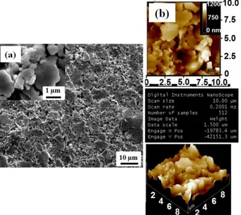
However, due to fast oxidation of Cu both during layer printing as well as upon electrochemical cycling, herein the example of Ag layer is solely chosen for emphasizing the benefit of the 4 and 3-layer configurations. Ag layers in different forms, includ-ing radio-frequency sputtered films or pasted ink were charac-terized. However, focusing on display applications Ag layer de-posited by flexography on paper substrate are solely used in this article. SEM and AFM images of Ag thin films deposited by flexography on paper substrate show porous textured surface with particles of various sizes exhibiting “cauliflower” shape associated with a roughness of 37 nm. (Fig. 2 a, b). Further-more, CVs not shown here of Ag film in (0.3 M) LiTFSI/BMITFSI show good electrochemical stability and du-rability in the electrochemical window of 0.1 to 0.5 V vs Hg/HgO. A metallic resistivity of 9.10-7 Ω·m was measured by
4-point probe measurement.
Figure 2. SEM (a) and AFM (b) images of Ag thick film de-posited on paper substrate by flexography.
3.2.2. Active Electrochromic layer
Among various investigated electrochromic materials including WO359, 60 and TiO2-viologen47, 61, 62,
poly(3,4-ethylenedioxythi-ophene) (PEDOT) based materials were chosen in respect of low activation potentials, high optical contrast, and fast
switch-ing speed36, 39, 63-65. In particular, PEDOT:PSS has recently
re-ceived increased interest for industrial applications due to its high electrical conductivity and good thermal stability66. In
ad-dition, PEDOT:PSS thin films exhibit high transparency in the visible range, long-term stability, and good solubility in water as non-toxic solvent67. PEDOT:PSS can be used as suitable
aqueous ink for room-temperature printing techniques, leading to promising electrochromic displays on flexible substrate such as paper68. Thus, in the following, examples of 4 and 3 layers
ECDs are based on the association of a Ag layer and a PEDOT based layer, namely PEDOT on ITO for the 4-layer ECD and PEDOT: PSS for the 3-layer ECD. A key point of ECDs re-mains the in-between layer, namely the electrolyte. Laminated devices were assembled by using a sticky membrane based on a mixture of ionic liquid and PMMA. Prior to device assembly, excellent cyclability of both PEDOT/ITO and PEDOT-PSS lay-ers were demonstrated in LiTFSI/BMITFSI electrolyte using three-electrode cells.
3.3. Electrochromic Behavior 3.3.1 4-layer device
For sake of understanding, we shall recall that the 4-layer ECD consists of PET/ITO/PEDOT/(0.3 M) LiTFSI/BMITFSI 40 % PMMA/Ag/paper. Figure 3a reports the cyclic voltammograms of 4-layer ECD cycled in between 0 V to – 0.7 V at a scan rate of 10 mV.s-1 while the reflectance curves recorded at initial
state, 0 V, -0.7 V and -1 V are shown in Figure 3b. 4-layer ECD switches from a light blue to deep blue color upon reduction from 0 V to -0.7 V. CVs of 4-layer ECD show superior revers-ibility and cyclability with a corresponding capacity of 1.0 mC.cm-2 (Fig. 3a) associated with a modulation of the contrast
in reflectance in between 350 and 700 nm (Fig. 3b) at 550 nm of about 4.4 % i. e. from 25.4 % to 29.8 %. The similarity in the reflectance spectra recorded at -0.7 V with the one at -1 V, em-phasizes the possibility of using a limited voltage window, namely 0.7 V. Coloration efficiency is one of the key feature of electrochromic materials and devices. Commonly for trans-mittive systems, the coloration efficiency (CE) is defined as the change in optical density ∆OD per unit-inserted charge. The ∆OD and coloration efficiency (CE) are calculated using the two relations:
∆OD=log(Tb/Tc)
Where, Tb and Tc are the transmittance of the EC film in the
bleached and colored states, respectively. CE= ∆OD/Q
Where, Q is the amount of charge transferred per unit area. In our case of reflective devices the ∆OD is calculated using the ∆OD=log(R0V/R-0.7V). A coloration efficiency of 69 cm2/Cwas
calculated.
As pointed out by Pooi See Lee and co-workers69, the CE of
reflective devices is relatively low as compared to transmittive ones. The switching time and corresponding activation energy, E, calculated using the E = U*Q- equation in which U is the
potential and Q- is the capacity, were deduced from the
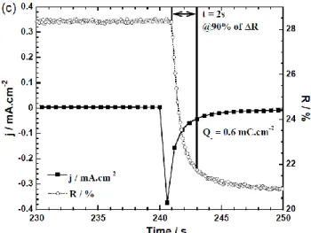
chrono-amperograms recorded after 60 sec. at -0.7 V (colored state) and 60 sec. at 0 V (bleached state) coupled to the in-situ reflectance at 550 nm. Figure 3c reports the third cycle showing a 90 %
4
optical switch in about 2 seconds for a corresponding capacity Q- equal to 0.6 mC.cm-2 and a calculated activation energy E of
0.4 mJ.cm-2. Those values are in the same order of the ones
de-duced from three-electrode cell measurements.
Figure 3. (a): Cyclic Voltammograms recorded between -0.7 V and 0 V with a scan rate of 10 mV.s-1 of 4-layer ECD:
PET/ITO/PEDOT/(0.3 M) LiTFSI/BMITFSI. 40 % PMMA/Ag/paper (visual appearances in the colored (-0.7 V) and the bleached (0 V) states) of 1 cm2 ECD. (b): reflectance
curves of initial, bleached at 0 V, and colored respectively at -0.7 V and at -1 V. (c): Chronoamperogram in coloration (--0.7 V) and in-situ reflectance variation at 550 nm wavelength show-ing switchshow-ing time and correspondshow-ing charges quantity. To complete, the reflectance measurements, a colorimetric method based on the CIE*L*a*b* color space was used70. The
latter is described using three parameters, L*, a*, b* that repre-sent lightness (normalized from 0, dark black to 100 bright white), red (positive)-green (negative) chromaticity and yellow (positive) blue (negative) chromaticity, respectively71.
The L*, a*, b* values in the bleached state (0 V) and in the col-ored states (-0.7 V and -1.0 V) are gathered in Table 1. In agree-ment with the blue appearance of the device, b* decreases from a positive value of 0.82 ± 0.50 (at 0 V) to a negative value of -28.34 ± 0.50 (at -0.7 V). The contrast (= [(L*c – L*b)2 + (a*c –
a*b)2 + (b*c – b*b)2] 1/2) calculated at -0.7 V is about 44. The
ΔE* = 51 at -1 V clearly showed that the difference is not sig-nificant. After 100 cycles (Fig. 4), the second cycle was com-pared with the 102nd one, in order to evaluate the charge
quan-tities variation (ΔQ-) and switching times. Coloration time has
increased from 2 to 5 sec. whereas Q- shows good stability with
ΔQ- losses of about 0.3. However, a significant degradation of
the optical properties at 550 nm when the 4-layer ECD is cycled over 100 chronoamperometric cycles is observed. The decrease in ΔR after 100 CA is explained by the peeling at the ITO and PEDOT interface shown in cross section by SEM (Fig. S1). Aiming at pursuing the device simplification and thus limiting the number of interfaces that may represent weak points, PEDOT on ITO/PET were replaced by PEDOT:PSS printed on PET substrate.
Table 1. L*, a*, b* parameters and ΔE* contrast of 4 layers PET/ITO/PEDOT/(0.3 M) LiTFSI/BMITFSI. 40 % PMMA/Ag/paper device in the colored (-0.7 V) and bleached (0 V) states.
5
Figure 4. Comparison between 2nd and 102nd
chronoam-perograms and the in-situ reflectance variation at 550 nm wave-length of 4-layer ECD : PET/ITO/PEDOT/(0.3 M) LiTFSI/BMITFSI. 40 % PMMA/Ag/paper recorded at 0 V/60 s and at -0.7 V/60 s.
3.3.2 3-layer device
For sake of understanding, we shall recall that the 3-layer ECD consists of PET/PEDOT:PSS/(0.3 M) LiTFSI/BMITFSI. 40 % PMMA/Ag/paper. In first approximation, CVs recorded be-tween -0.7 V and 0 V at 10 mV.s-1 scan rate of 3-layer ECD
(Fig. 5a), show similar electrochemical behavior than the ones of 4-layer ECD exhibiting good reversibility with nevertheless, smaller capacity (i.e ECD3-layer: 0.6 mC.cm-2 < ECD4-layer :
1.0 mC.cm-2). Electrochemical performances are associated
with a nice optical contrast in ΔR of about 6.0 % at 550 nm (Fig. 5b), in between the colored (-0.7 V) and bleached state (0 V). The slight difference in the initial appearance of the 4 and 3-layer ECDs simply results from various thicknesses of PEDOT based films, thicker films being darker.
On the contrary to 4-layer ECD, the current density is not equal to zero during cycling at maximum color state due to the high resistance (R□ = 500 ± 10 Ω.sq) of PEDOT: PSS film. The
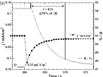
ac-tivation energy of 3-layer ECD calculated from chronoam-perometry coupled with in-situ reflectance measurement at 550 nm (Fig. 5c) is about 0.25 mJ.cm-2. The 3-layer ECD
mod-ifies its reflectance from 0 V to -0.7 V in 8.5 seconds associated with charge quantity Q- of 0.35 mC.cm-2. The contrast ΔE*
in-creases from 34 to 47 by decreasing the voltage from -0.7 V to -1 V (Table 2). Upon cycling in between 0 and -0.7 V, the charge capacity, Q- remains stable at a value around 0.8 mC.cm -2 with a slight increase of coloration time from 8.5 to 10 sec.
between the second cycle and 102nd one (Fig. 6). On the
con-trary to the 4-layer device, the optical properties remain stable up to 100 cycles. A CE of 88 cm2/C is calculated.
U (V) L* a* b* ΔE*
0 48.12 ± 1.0 -1.02 ± 0.20 0.82 ± 0.50 -
-0.7 18.35 ± 1.0 12.22 ± 0.20 -28.34 ± 0.50 44
6
Figure 5. (a): Cyclic Voltammetry recorded between -0.7 V and 0 V at 10 mV.s-1 scan rate of 3-layer ECD:
PET/PEDOT:PSS/(0.3 M) LiTFSI/BMITFSI. 40 % PMMA/Ag/paper (visual appearances in the colored (-0.7 V) and the bleached (0 V) states). (b): reflectance curves of initial, bleached at 0 V, and colored respectively at -0.7 V and at -1 V. (c): Chronoamperogram in coloration (-0.7 V) and reflectance variation in-situ at 550 nm wavelength showing switching time and corresponding current density vs time evolution.
Figure 6. Comparison between 6th and 102nd
chronoam-perograms and the reflectance variation in-situ at 550 nm wave-length of 3-layer ECD : PET/PEDOT:PSS/(0.3 M) LiTFSI/BMITFSI. 40 % PMMA/Ag/paper recorded at 0 V/60 s and at -0.7 V/60 s.
3.4. Preliminary insight in the mechanism
Preliminary insight in the involved mechanism in the unusual 4 and 3 layers ECDs based on a metallic layer as counter electrode was deduced from XPS analysis. 4-layer ECD, PET/ITO/PEDOT/Li based electrolyte/Ag plate, was cycled up to 1100 times by chronoamperometry applying successive steps of 30 sec. at -0.7 V and 0.0 V. The cycling behavior shows an initial decrease in capacity followed by a fairly stable state prior to a decrease in capacity after 900 cycles. After 500 and 1100 cycles, 4-layer ECD was dismantled and each side character-ized by XPS. Interestingly, The set of XPS spectra on the PEDOT based electrode etched for 300 sec is shown in Fig.
7(a,b). The Ag presence was detected after cycling and its pres-ence on the PEDOT based electrode supports the double role of conductive and active layer played by the Ag plate as concluded by Faure et al.72 on a similar approach describing systems using
copper foil conductive counter electrode.
Figure 7. XPS spectra of Ag 3d regions of the 500 (a) and 1100 (b) cycled PEDOT layer.
3.5. Towards Applications
As an illustration of applications requiring low power display, 4 and 3-layer ECDs were activated using a modern life tool, namely a smartphone operating in a Wi-Fi mode73 for
all-printed label. In this system, the optimization of the electronic circuit, which consists of an antenna, a rectifier system assisted by Shootky diodes is reported elsewhere74. Concerning the
dis-play, the development of ECDs on paper required to adjust the printability of each layer and in particular of the electrolyte, of which composition plays a key role. In our group we reported original electrochromic performances for NiO-PEDOT ECDs using lithium free electrolyte75 and in particular BMITFSI.
Aiming at simplifying the electrolyte composition (i.e. Lithium free electrolyte), the cycling properties of PEDOT / and PEDOT-PSS films in BMITFSI electrolyte were studied (Fig. 8a, b). The comparison of CVs of PEDOT/ITO/PET films cy-cled in LiTFSI-BMITFSI and BMITFSI as well as of the elec-trochemical and optical properties including PEDOT-PSS films confirm the good electrochromic properties in lithium free elec-trolyte (Fig. 8c, d). 364 366 368 370 372 374 376 378 380 0s 60s 120s 180s 240s 300s C o u n ts / s / a .u . Binding Energy / eV Ag 3d 3/2 Ag 3d 5/2 (a) 364 366 368 370 372 374 376 378 380 0s 60s 120s 180s 240s 300s C o u n ts / s / / a .u . Binding Energy / eV Ag 3d 3/2 Ag 3d 5/2 (b)
7
Table 2. L*, a*, b* parameters and ΔE* contrast of 4 layers PET/PEDOT:PSS/(0.3 M) LiTFSI/BMITFSI. 40 % PMMA/Ag/paper device in the colored (-0.7 V) and bleached (0 V) states.
Figure 8. Cyclic voltammograms and in-situ transmittance at 550 nm wavelength recorded between -1 V and +1 V of (a) : PET/ITO/PEDOT and (b) : PET/PEDOT:PSS thin films cycled in PEDOT/BMITFSI/Pt vs Hg/HgO cell with a scan rate of 10 mV.s-1. Comparison of the 10th cyclic voltammograms of (c) :
PET/ITO/PEDOT and (d) : PET/PEDOT:PSS thin film cycled in both (0.3M) LiTFSI/BMITFSI and BMITFSI.
U (V) L* a* b* ΔE*
0 54.83 ± 1.0 -0.61 ± 0.20 1.92 ± 0.50 -
-0.7 47.41 ± 1.0 9.02 ± 0.20 -30.11 ± 0.50 34
8
The coloration efficiency is even increased in BMITFSI elec-trolyte (Table 3). Nevertheless, a significant increase in switch-ing times is also observed from 5 sec (in LiTFSI-BMITFSI) to 17 sec (BMITFSI). The close values of the ionic conductivities deduced from EIS measurements, namely (σ(LiTFSI-BMITFSI ≈ 3.6 mS.cm-1 < σ(BMITFSI ≈ 5.1 mS.cm-1) could not explain
such increase. The slower kinetic of the BMITFSI device may illustrate a poorer interface quality.
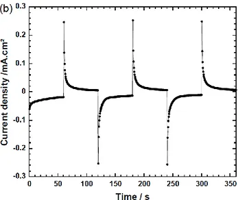
In our approach, aiming at manufacturing all-printed device sandwiched between two paper substrates at low temperature (T < 100°C), we combine the flexography tool for PEDOT:PSS and silver inks and the screen printing technique for new elec-trolyte composition based on BMITFSI and UV-polymerized varnish. Two types of 3-layer ECDs were fabricated. Silver ink with controlled viscosity (η(25°C) = 350 cP) was printed on pa-per substrate as counter electrode and as conductor grid on trac-ing paper (second substrate). PEDOT:PSS film was printed on tracing paper/Ag grid after modifying ink viscosity by heating at 80°C to prevent any degradation of paper. In the second ex-periment, semi-automatic screen printer (EKRA X1-SL) and UV lamp (Fusion UV, Hammer 6) were used to sandwich BMITFSI. 60 w. % varnish between silver and PEDOT: PSS electrodes. Figures 9a, b report CV and CA curves respectively showing similar electrochemical behavior than four and three layers devices with nice color change from -0.7 V to 0 V (shown in Fig. 9a inset) except the charge quantities which were in-creased up to 1.2 mC.cm-2. The coloration energy of “smiley”
label was around 0.12 mJ associate to CIE* ΔE* of about 38.
Figure 9. Cyclic voltammograms (a) started on reduction in be-tween -0.7 V and 0 V with a scan rate of 10 mV.s-1 of tracing
paper/Ag grid/PEDOT:PSS/BMITFSI. 60 % varnish UV/Ag/paper, inset : cross-section and reversible color chang-ing pictures of EC device from bluish (-0.7 V) to bleached (0 V) states. Chronoamperograms (b) performed at -0.7 V for 60 s and 0 V for 60 s.
Having optimized the various parts of the system (electronic circuit – 60 mm × 45 mm rectenna) and electrochromic display, innovative prototype was incorporated in a perfume packaging. Consequently, with 1 mJ.cm-² (−15 dBm) delivered by a wire-less power phone located in proximity to the smart packaging, the incorporated electrochromic display was successfully turned on demonstrating nice switching from colorless to blue state (Fig. 10).
Figure 10. Illustration of the purpose of our work showing the activation of 4-layer ECD printed on perfume packaging by smartphone power.
Table 3. Electrochromic properties, namely charge quantity in coloration Q-, optical contrast in transmittance ΔT550nm, Coloration
efficiency CE, and switching times in coloration tC and bleaching tB of ITO/PEDOT and PEDOT:PSS thin films cycled respectively
9
In summary, electrochromic devices, with simplified architec-ture, combining metal as electronic conductor and counter elec-trode and electrochromic conductive material were developed leading to innovative ECDs based on four and three layers. 3 and 4-layer ECDs show high optical contrasts in reflectance for an activation potential as low as -0.7 V using Ag as conductive counter electrode and PEDOT derivatives as electrochromic layer. Preliminary characterization of the involved mechanism shows the presence of Ag on the PEDOT electrode after cycling while no significant decrease in performance were recorded. As an ultimate goal, the activation of the simplified 3 or 4 layers ECDs using a cell phone is successfully demonstrated opening the field of applications for electronic printed paper.
Supporting Information.
S1: SEM images of cross section of 4-layer before and after 500 cycles.
*E-mail: aline.rougier@icmcb.cnrs.fr
The manuscript was written through contributions of all authors.
The authors wish to thank the ANR PEPS for financial support and CTP for paper substrate and printing tools. The authors wish to thank the ANR PEPS partners for fruitful discussions and in par-ticular Max Braha-Lonchant from Luquet-Duranton. The ICMCB staff wishes to thank in particular Guy Campet for very fruitful dis-cussions as well as Alexandre Fargues (ICMCB) for his help in op-tical measurements.
PEDOT:PSS, (poly(3,4-ethylenedioxythiophene) poly(styrenesul-fonate)); TCO, Transparent Conducting Oxide; EC, Electro-chromic Layer; ECD, ElectroElectro-chromic devices; PMMA, Poly(me-thyl methacrylate); LiTFSI/BMITFSI, Lithium bis(trifluoro-methanesulfonyl)imide in 1-butyl-3-methylimidazolium bis(tri-fluoromethanesulfonyl)imide.
(1) Baucke, F. G. K., Electrochromic Applications. Mater.
Sci. Eng. B: Adv. 1991, 10(4), 285-292.
(2) Deb, S. K., A Novel Electrophotographic System. Appl.
Optics 1969, 8(S1), 192-195.
(3) Monk, P.; Mortimer, R.; Rosseinsky, D., Electrochromism and Electrochromic Devices. Cambridge
University Press, New York: United States of America 2007
(ISBN : 978-0-521-82269-5).
(4) Granqvist, C. G., Preface. Handbook of Inorganic
Electrochromic Materials, Elsevier Science, Amsterdam
1995, vii-viii (ISBN : 978-0-444-89930-9).
(5) Diesbach, Gmelin, Handbuch Der Anorganischen
Chemie. Frankfurt and Main: Deutsche Chemische
Gesellschaft 1930, 59, 671.
(6) Ware, M., Prussian Blue: Artists' Pigment and Chemists' Sponge. J. Chem. Edu. 2008, 85(5), 612-620.
(7) Neff, V. D., Electrochemical Oxidation and Reduction of Thin Films of Prussian Blue. J. Electrochem. Soc. 1978,
125(6), 886-887.
(8) Itaya, K.; Uchida, I.; Neff, V. D., Electrochemistry of Polynuclear Transition Metal Cyanides: Prussian Blue and its Analogues. Acc. Chem. Res. 1986, 19(6), 162-168. (9) Hedley, L.; Porteous, L.; Hutson, D.; Robertson, N.; Johansson, J. O., Electrochromic Bilayers of Prussian Blue and its Cr Analogue. J. Mater. Chem. C 2018, 6(3), 512-517. (10) Deb, S. K., Optical and Photoelectric Properties and Colour Centres in Thin Films of Tungsten Oxide. Philos.
Mag. 1973, 27(4), 801-822.
(11) http://www.gentex.com/automotive/mirror-module. (12) http://www.gentex.com/aerospace/aircraft-windows. (13) Xu, C.; Ma, C.; Taya, M., Smart Sunglasses, Helmet Faceshields and Goggles Based on Electrochromic Polymers. Patent N° : US2008/0239452 A1 - Pub. Date : Oct. 2, 2008.
EC thin film Electrolyte Q
-mC.cm-2 ΔT550nm % CE cm².C-1 tC Seconds tB Seconds ITO/PEDOT (0.3M) LiTFSI/BMITFSI 5.0 50 155 2 3 BMITFSI 4.8 55 202 17 18 PEDOT:PSS (0.3M) LiTFSI/BMITFSI 1.7 17 58 4 5 BMITFSI 1.4 14 57 34 24
10
(14) http://sageglass.com/technology/how-it-works.(15) http://www.chromogenics.com.
(16) Kim, K.-W.; Lee, S. B.; Kim, S. H.; Moon, H. C., Spray-Coated Transparent Hybrid Electrodes for High-Performance Electrochromic Devices on Plastic. Org.
Electron. 2018, 62, 151-156.
(17) Zhang, Q.; Tsai, C.-Y.; Abidin, T.; Jiang, J.-C.; Shie, W.-R.; Li, L.-J.; Liaw, D.-J., Transmissive-To-Black Fast Electrochromic Switching From a Long Conjugated Pendant Group and a Highly Dispersed Polymer/SWNT. Polym.
Chem. 2018, 9(5), 619-626.
(18) Chen, X.; Qu, Q., Synthesis and Optoelectrochemical Properties of a Magenta-to-Transmissive Electrochromic Polymer Based on 3, 4-Dioxythiophene. Sol. Energy Mater.
Sol. Cells 2018, 179, 270-275.
(19) Cho, S. M.; Kim, T.-Y.; Ah, C. S.; Song, J.; Cheon, S. H.; Ryu, H.; Kim, J. Y.; Kim, Y.-H.; Hwang, C.-S., Electrochromic Device With Self-Diffusing Function for Light Adaptable Displays. S Sol. Energy Mater. Sol. Cells
2018, 177, 89-96.
(20) Barawi, M.; Veramonti, G.; Epifani, M.; Giannuzzi, R.; Sibillano, T.; Giannini, C.; Rougier, A.; Manca, M., A Dual Band Electrochromic Device Switchable Across Four Distinct Optical Modes. J. Mater. Chem. A 2018, 6(22), 10201-10205.
(21) Mandal, J.; Du, S.; Dontigny, M.; Zaghib, K.; Yu, N.; Yang, Y., Li4Ti5O12: A Visible-to-Infrared Broadband
Electrochromic Material for Optical and Thermal Management. Adv. Funct. Mater. 2018, 28(36), 1802180. (22) Zhou, C.; Zhou, H.; Zuo, H.-P.; Zhang, K.-F.; Wang, H.; Xiong, Y.-Q., A Reflective Inorganic All-Thin-Film Flexible Electrochromic Device with a Seven-Layer Structure. Chin. Phys. Lett. 2018, 35(7), 077801.
(23) Gu, H.; Guo, C.; Zhang, S.; Bi, L.; Li, T.; Sun, T.; Liu, S., Highly Efficient, Near-Infrared and Visible Light Modulated Electrochromic Devices Based on Polyoxometalates and W18O49 Nanowires. ACS Nano 2018,
12 (1), 559-567.
(24) DeForest, N.; Shehabi, A.; Selkowitz, S.; Milliron, D.J., A Comparative Energy Analysis of Three Electrochromic Glazing Technologies in Commercial and Residential Buildings. Applied Energy 2017, 192, 95-109. (25) Kelly, F. M.; Meunier, L.; Cochrane, C.; Koncar, V., Polyaniline : Application as Solid State Electrochromic in a Flexible Textile Display. Displays 2013, 34 (1), 1-7. (26) Comiskey, B.; Albert, J. D.; Yoshizawa, H.; Jacobson, J., An Electrophoretic Ink for All-Printed Reflective Electronic Displays. Nature 1998, 394 (6690), 253-255. (27) Chen, Y.; Au, J; Kazlas, P.; Ritenour, A.; Gates, H.; McCreary, M., Electronic Paper: Flexible Active-Matrix Electronic Ink Display. Nature 2003, 423, 136-262. (28) http://www.ynvisible.com.
(29) Huiberts, J.N.; Griessen, R.; Rector, J.H.; Wijngaarden, R.J.; Dekker, J.P.; de Groot, D.G.; Koeman, N.J., Yttrium and Lanthanum Hydride Films with Switchable Optical Properties. Nature 1996, 380, 231-234. (30) Richardson, T.J.; Slack, J.L.; Armitage, R.D.; Kostecki, R.; Farangis, B.; Rubin, M.D., Switchable Mirrors Based on Nickel–Magnesium Films. Applied
Physics Letters 2001, 78 (20), 3047-3049.
(31) Shirakawa, H.; Louis, E.J.; MacDiarmid, A.G.; Chiang, C.K.; Heeger, A.J., Synthesis of Electrically Conducting Organic Polymers: Halogen Derivatives of Polyacetylene, (CH). Journal of the Chemical Society,
Chemical Communications 1977, (16), 578-580.
(32) Chiang, C.K.; Druy, M.A.; Gau, S.C.; Heeger, A. J.; Louis, E.J.; MacDiarmid, A.G.; Park, Y.W.; Shirakawa, H., Synthesis of Highly Conducting Films of Derivatives of Polyacetylene, (CH)x. J. Am. Chem. Soc. 1978, 100 (3), 1013-1015.
(33) Chiang, C.K.; Fincher, C.R.; Park, Y.W.; Heeger, A.J.; Shirakawa, H.; Louis, E.J.; Gau, S.C.; MacDiarmid, A.G., Electrical Conductivity in Doped Polyacetylene. Phys.
Rev. Lett. 1977, 39 (17), 1098-1101.
(34) Sapp, S.A.; Sotzing, G.A.; Reddinger, J.L.; Reynolds, J.R., Rapid Switching Solid State Electrochromic Devices Based on Complementary Conducting Polymer Films. Adv.
Mater. 1996, 8 (10), 808-811.
(35) Arbizzani, C.; Mastragostino, M.; Zanelli, A., Electrochromic Devices: A Comparison of Several Systems.
Sol. Energy Mater. Sol. Cells 1995, 39 (2), 213-222.
(36) Groenendaal, L.; Jonas, F.; Freitag, D.; Pielartzik, H.; Reynolds, J.R., Poly(3,4-ethylenedioxythiophene) and Its Derivatives: Past, Present, and Future. Adv. Mater. 2000, 12 (7), 481-494.
(37) Groenendaal, L.; Zotti, G.; Aubert, P.H.; Waybright, S.M.; Reynolds, J.R., Electrochemistry of Poly(3,4-alkylenedioxythiophene) Derivatives. Adv. Mater. 2003, 15 (11), 855-879.
(38) Çetin, G.A.; Balan, A.; Durmuş, A.; Günbaş, G.; Toppare, L., A New P- and N-Dopable Selenophene Derivative and its Electrochromic Properties. Org. Electron.
2009, 10 (1), 34-41.
(39) Kirchmeyer, S.; Reuter, K., Scientific Importance, Properties and Growing Applications of Poly(3,4-ethylenedioxythiophene). J. Mater. Chem. 2005, 15 (21), 2077-2088.
(40) Monk, P.M.S., The viologens : Physicochemical
Properties, Synthesis and Applications of the Salts of 4,4'-Bipyridine. Wiley : Chichester, 1998.
(41) M. S. Monk, P.; J. Mortimer, R.; Rosseinsky, D.,
Electrochromism: Fundamentals and Applications. 2007; p
I-XXIII.
(42) Summers, L. A., The Bipyridines. In Advances in
Heterocyclic Chemistry, Katritzky, A. R., Ed. Academic
Press, 1984, 35, 281-374.
(43) Chang, T.-H.; Lu, H.-C.; Lee, M.-H.; Kao, S.-Y.; Ho, K.-C., Multi-Color Electrochromic Devices Based on Phenyl and Heptyl Viologens Immobilized with UV-Cured Polymer Electrolyte. Sol. Energy Mater. Sol. Cells 2018,
177, 75-81.
(44) Bird, C.L.; Kuhn, A.T., Electrochemistry of the Viologens. Chem. Soc. Rev. 1981, 10 (1), 49-82.
(45) Bard, A.J.; Ledwith, A.; Shine, H.J., Formation, Properties and Reactions of Cation Radicals in Solution. In
Advances in Physical Organic Chemistry, Gold, V.; Bethell,
D., Eds. Academic Press 1976, 13, 155-278.
(46) Sliwa, W.; Bachowska, B.; Zelichowicz, N., Chemistry of Viologens. Heterocycles 1991, 32 (11), 2241-2273. (47) Danine, A.; Manceriu, L.; Fargues, A.; Rougier, A., Eco-Friendly Redox Mediator Gelatin-Electrolyte for
11
Simplified TiO2-Viologen Based Electrochromic Devices.Electrochim. Acta 2017, 258, 200-207.
(48) Costa, C.; Pinheiro, C.; Henriques, I.; Laia, C.A.T., Inkjet Printing of Sol–Gel Synthesized Hydrated Tungsten Oxide Nanoparticles for Flexible Electrochromic Devices.
ACS Appl. Mater. Interfaces 2012, 4 (3), 1330-1340.
(49) Wojcik, P.J.; Cruz, A.S.; Santos, L.; Pereira, L.; Martins, R.; Fortunato, E., Microstructure Control of Dual-Phase Inkjet-Printed a-WO3/TiO2/WOX Films for
High-Performance Electrochromic Applications. J. Mater. Chem.
2012, 22 (26), 13268-13278.
(50) Danine, A.; Cojocaru, L.; Faure, C.; Olivier, C.; Toupance, T.; Campet, G.; Rougier, A., Room Temperature UV Treated WO3 Thin Films for Electrochromic Devices on
Paper Substrate. Electrochim. Acta 2014, 129, 113-119. (51) Andersson Ersman, P., Roll To Roll Printable Technology Platform Consisting of Electrolyte-Based Components. In LOPE-C 2011, Frankfurt, Germany, 2011. (52) Corr, D.; Bach, U.; Fay, D.; Kinsella, M.; McAtamney, C.; O'Reilly, F.; Rao, S.N.; Stobie, N., Coloured Electrochromic “Paper-Quality” Displays Based on Modified Mesoporous Electrodes. Solid State Ion. 2003,
165 (1–4), 315-321.
(53) Takada, K.; Sakamoto, R.; Yi, S.-T.; Katagiri, S.; Kambe, T.; Nishihara, H., Electrochromic Bis(terpyridine)metal Complex Nanosheets. J. Am. Chem.
Soc. 2015, 137 (14), 4681-4689.
(54) http://en.solvionic.com.
(55) Granqvist, C.G., Electrochromics for Smart Windows: Oxide-Based Thin Films and Devices. Thin Solid Films
2014, 564, 1-38.
(56) Dong, D.; Wang, W.; Barnabé, A.; Presmanes, L.; Rougier, A.; Dong, G.; Zhang, F.; Yu, H.; He, Y.; Diao, X., Enhanced Electrochromism in Short Wavelengths for NiO:(Li, Mg) Films in Full Inorganic Device ITO/NiO:(Li, Mg)/Ta2O5/WO3/ITO. Electrochim. Acta 2018, 263,
277-285.
(57) Lin, F.; Nordlund, D.; Weng, T.-C.; Sokaras, D.; Jones, K.M.; Reed, R.B.; Gillaspie, D.T.; Weir, D.G.J.; Moore, R.G.; Dillon, A.C.; Richards, R.M.; Engtrakul, C., Origin of Electrochromism in High-Performing Nanocomposite Nickel Oxide. ACS Appl. Mater. Interfaces
2013, 5(9), 3643-3649.
(58) Shankar, S.; Lahav, M.; van der Boom, M. E., Coordination-Based Molecular Assemblies as Electrochromic Materials: Ultra-High Switching Stability and Coloration Efficiencies. J. Am. Chem. Soc. 2015, 137 (12), 4050-4053.
(59) Sauvet, K.; Sauques, L.; Rougier, A., IR Electrochromic WO3 Thin Films: From Optimization to
Devices. Sol. Energy Mater. Sol. Cells 2009, 93 (12), 2045-2049.
(60) Kim, H.; Choi, D.; Kim, K.; Chu, W.; Chun, D.-M.; Lee, C.S., Effect of Particle Size and Amorphous Phase on the Electrochromic Properties of Kinetically Deposited WO3
Films. Sol. Energy Mater. Sol. Cells 2018, 177, 44-50. (61) Cinnsealach, R.; Boschloo, G.; Nagaraja Rao, S.; Fitzmaurice, D., Electrochromic Windows Based on Viologen-Modified Nanostructured TiO2 Films. Sol. Energy
Mater. Sol. Cells 1998, 55 (3), 215-223.
(62) Alesanco, Y.; Viñuales, A.; Ugalde, J.; Azaceta, E.; Cabañero, G.; Rodriguez, J.; Tena-Zaera, R., Consecutive Anchoring of Symmetric Viologens: Electrochromic Devices Providing Colorless To Neutral-Color Switching.
Sol. Energy Mater. Sol. Cells 2018, 177, 110-119.
(63) Yue, Y.; Li, H.; Li, K.; Wang, J.; Wang, H.; Zhang, Q.; Li, Y.; Chen, P., High-Performance Complementary Electrochromic Device Based on WO3·0.33H2O/PEDOT
and Prussian Blue Electrodes. Journal of Physics and
Chemistry of Solids 2017, 110, 284-289.
(64) Louet, C.; Cantin, S.; Dudon, J.-P.; Aubert, P.-H.; Vidal, F.; Chevrot, C., A Comprehensive Study of Infrared Reflectivity of Poly(3,4-ethylenedioxythiophene) Model Layers with Different Morphologies and Conductivities.
Sol. Energy Mater. Sol. Cells 2015, 143, 141-151.
(65) Ouyang, J.; Chu, C. W.; Chen, F. C.; Xu, Q.; Yang, Y., High-Conductivity Poly(3,4-ethylenedioxythiophene): Poly(styrene sulfonate) Film and Its Application in Polymer Optoelectronic Devices. Adv. Funct. Mater. 2005, 15(2), 203-208.
(66) Huang, J.; Miller, P.F.; de Mello, J.C.; de Mello, A. J.; Bradley, D.D.C., Influence of Thermal Treatment on the Conductivity and Morphology of PEDOT/PSS Films.
Synthetic Metals 2003, 139 (3), 569-572.
(67) Hu, Z.; Zhang, J.; Zhu, Y., Effects of Solvent-Treated PEDOT:PSS on Organic Photovoltaic Devices. Renewable
Energy 2014, 62, 100-105.
(68) Andersson, P.; Nilsson, D.; Svensson, P.-O.; Chen, M.; Malmström, A.; Remonen, T.; Kugler, T.; Berggren, M., Active Matrix Displays Based on All-Organic Electrochemical Smart Pixels Printed on Paper. Adv. Mater.
2002, 14 (20), 1460-1464.
(69) Chaoyi Yan,Wenbin Kang, Jiangxin Wang, Mengqi Cui, Xu Wang, Ce Yao Foo, Kenji Jianzhi Chee, and Pooi See Lee, Stretchable and Wearable Electrochromic Devices
ACS Nano. 2014, 8(1), 316-322 .
(70) Thompson, B.C.; Schottland, P.; Zong, K.; Reynolds, J.R., In Situ Colorimetric Analysis of Electrochromic Polymers and Devices. Chem. Mater. 2000, 12(6), 1563-1571.
(71) Kawahara, J.; Ersman, P.A.; Engquist, I.; Berggren, M., Improving the Color Switch Contrast in PEDOT:PSS-based Electrochromic Displays. Org. Electron. 2012, 13 (3), 469-474.
(72) Faure, C.; Guerfi, A.; Dontigny, M.; Clément, D.; Hovington, P.; Posset, U.; Zaghib, K., High Cycling Stability of Electrochromic Devices Using a Metallic Counter Electrode. Electrochim. Acta 2016, 214, 313-318. (73) Eymin-Petot-Tourtollet, G.; Braha-Lonchant, M.; Verelst, M.; Campet, G.; Rougier, A.; Vuong, T.-P.; Benech, P.; Xavier, P.; Duchamp, J.-M. Dispositif Electronique d'Affichage, French Patent, June 16, 2011, n° 11/55286 - Réf. B11016 FR, Pub. N° : 2976705 - December, 21, 2012.
(74) Kharrat, I.; Xavier, P.; Vuong, T.-P.; Eymin-Petot-Tourtollet, G., Compact Rectenna Design for Lossy Paper Substrate at 2.45 Ghz. Progress In Electromagnetics
Research C 2016, 62, 61-70.
(75) Mihelčič, M.; Šurca Vuk, A.; Jerman, I.; Orel, B.; Švegl, F.; Moulki, H.; Faure, C.; Campet, G.; Rougier, A., Comparison of Electrochromic Properties of Ni1−xO in
12
Lithium and Lithium-Free Aprotic Electrolytes: FromNi1−xO Pigment Coatings to Flexible Electrochromic
Devices. Sol. Energy Mater. Sol. Cells 2014, 120(Part A), 116-130.