HAL Id: hal-01024405
https://hal-enpc.archives-ouvertes.fr/hal-01024405
Submitted on 16 Jul 2014
HAL is a multi-disciplinary open access
archive for the deposit and dissemination of
sci-entific research documents, whether they are
pub-lished or not. The documents may come from
teaching and research institutions in France or
abroad, or from public or private research centers.
L’archive ouverte pluridisciplinaire HAL, est
destinée au dépôt et à la diffusion de documents
scientifiques de niveau recherche, publiés ou non,
émanant des établissements d’enseignement et de
recherche français ou étrangers, des laboratoires
publics ou privés.
A simple method for numerical modelling of energy
pile’s mechanical behaviour
Neda Yavari, Anh Minh Tang, Jean-Michel Pereira, Ghazi Hassen
To cite this version:
Neda Yavari, Anh Minh Tang, Jean-Michel Pereira, Ghazi Hassen. A simple method for numerical
modelling of energy pile’s mechanical behaviour. Géotechnique Letters, ICE Publishing, 2014, 4
(April-June), pp.119-124. �10.1680/geolett.13.00053�. �hal-01024405�
● Article type: paper
● Date text written: July 22, 2013; revised: October 14, 2013 ● 2146 words, 2 tables, 7 figures
--- --
A simple method for numerical modelling of energy pile’s mechanical behaviour
Author 1
● YAVARI Neda, PhD student
● Laboratoire Navier, Université Paris-Est, Marne-la-Vallée, France Author 2
● TANG Anh Minh, Dr.
● Laboratoire Navier, Université Paris-Est, Marne-la-Vallée, France Author 3
● PEREIRA Jean-Michel, Dr.
● Laboratoire Navier, Université Paris-Est, Marne-la-Vallée, France Author 4
● HASSEN Ghazi, Dr.
● Laboratoire Navier, Université Paris-Est, Marne-la-Vallée, France
Full contact details of corresponding author: Dr. Jean-Michel PEREIRA
Ecole des Ponts ParisTech
Laboratoire Navier/Géotechnique (CERMES) 6-8 avenue Blaise Pascal
77455 MARNE-LA-VALLEE France Tel: +33.1.64.15.35.48
2
Abstract
A commercial numerical code was used to simulate the mechanical behaviour of energy piles under thermo-mechanical loadings. The thermal load was simply simulated by imposing to the pile volumetric strains calculated from the coefficient of thermal expansion of the material. Simulation was performed for two existing in-situ experiments and one experiment performed using physical model in laboratory. Comparison between the simulation and the experimental results shows that this decoupling method can predict satisfactorily the phenomena observed experimentally: (i) pile head movement under thermal cycles at various mechanical loads; (ii) change of pile axial load along the pile under thermal cycles. The results highlight the important role played by the thermal volume change of the pile on the mechanical behaviour of the energy pile under thermo-mechanical loadings.
Keywords
Piles; Soil/structure interaction; Temperature effects.
List of notations
α volumetric coefficient of thermal expansion
γ density
φ internal friction angle
c soil cohesion
Ψ dilation angle
E elastic modulus
poisson‟s ratioIntroduction
Exchanging heat with the surrounding soil while transferring structure‟s loads to the ground
make energy piles double function foundations. Although having been introduced to the world of construction for more than three decades, various aspects of this technology stay relatively unknown. Some existing studies show that heating can: (i) produce additional stresses in the
pile; (ii) reduce adhesion forces at pile‟s interface; (iii) and disturb thermal equilibrium of soil due
to non-balanced heat extraction-injection during heating and cooling cycles (Fromentin et al., 1999). As an engineer it would be interesting to have a numerical code for prediction of the pile behaviour under thermo-mechanical loads and according to that, considering appropriate parameters and safety factors in design procedures. Especially during recent years some
3
attempts have been made in order to produce such a program, from complicated finite element codes to simpler tools, particularly based on the load transfer method (Laloui et al., 2006; Peron et al., 2011; Knellwolf et al., 2011; Suryatriyastuti et al., 2012).
In the present work, a commercial finite element code well-suited for geotechnical analyses was used to model the mechanical behaviour of energy piles under thermo-mechanical loadings. The thermal loading was simply simulated by imposing to the pile volumetric strains corresponding to thermal strains. The simulations were compared to existing data on in-situ and physical model tests.
2. Experimental studies
Three existing experimental studies have been considered. The first one corresponds to the in-situ tests presented by Laloui et al. (2003). A pile in-situated below a building under construction was equipped with a heating system, load cells, strain gauges, and thermometers. The drilled pile diameter was 0.88 m and the length was 25.8 m. The geological profile is summarised in Table 1. At various stages of the construction of the building, the temperature of the pile was increased by approximately 15°C and then the system was let cool down to the initial temperature. The first test (T1) was performed before starting the construction when pile head was free to move. The other tests (T2 to T7) correspond to the heating/recovery test at the end of each construction stage. The results obtained show pile‟s head displacement and variation of axial strain along the pile under different head loads during heating/recovery tests.
The second study considered is that presented by Bourne-Webb et al. (2009) and Amatya et al. (2012). A loading-test pile, 0.55 m in diameter and 23 m in length, including pipe loops for temperature control was installed in London Clay. After applying a constant mechanical load at the pile head, heating/cooling cycles were applied to the pile; the temperature of the fluid circulating in the pile was varied between -2.5°C and 36°C. Temperature and strain were measured at various locations along the pile during the thermo-mechanical loading. The movement at the pile head was also recorded.
In the third work, Kalantidou et al. (2012) studied the soil/pile interaction while changing the temperature of the pile. A model pile, which was a closed-end aluminium tube of 20 mm in external diameter and 600 mm in length having its surface coated with sand, was embedded in
compacted dry sand. After applying the axial load on the pile‟s head, pile was heated from 25°C
to 50°C and the system was let cool down to 25°C. The pile‟s temperature and the pile head
4
3. Numerical modelling
3.1. Methods
A two-dimensional finite element program, Plaxis 2D, was used in order to model the behaviour of energy piles from the three studies mentioned above. The models are considered to be axisymmetric. The dimensions are exactly the same as that of experiments. In the case of in-situ tests, the extension of the simulated domain is chosen large enough to avoid boundary effects (at least 30 times the pile diameter). In the case of the physical model (Kalantidou et al., 2012), the dimensions of the soil container are precisely known and the same sizes are chosen in the simulation. As an example, the mesh used for simulating the test presented by Laloui et al. (2003) is shown in Figure 1.
The pile was modelled as an isotropic linear elastic non-porous material. For the soil, an isotropic linear elastic material with a failure criterion of Mohr-Coulomb type is chosen. The constitutive drained parameters and the drainage conditions are summarised in Tables 1 and 2. The parameters and the drainage conditions for the case of Laloui et al. (2003) are chosen according to numerical studies of Laloui et al. (2006). For the case of Bourne-Webb et al. (2009) parameters and drainage conditions are chosen following Amatya et al. (2012), Reeves et al. (2006) and Karakus & Fowell (2005). For the case of Kalantidou et al. (2012), the soil parameters are chosen according to the ones proposed by De Gennaro et al. (2008) for Fontainebleau sand. For evaluating the pile stiffness, considering that the pile used was an empty cylinder of aluminium, the modulus of elasticity is calculated for the equivalent section.
For the three cases, the soil/pile interface was considered perfectly rough; in other words, no interface element was added. This assumption does not seem unrealistic considering the concrete surface of the in-situ piles and the sand-coated surface of the small scale model pile. Note that the interface elements are usually used when studying soil/pile interaction under complex mechanical loading, including cyclic and lateral ones (Yang & Jeremic, 2005; Nogami et al., 1992; Said, 2004). In the present study, mesh is refined in this zone, where significant stress gradients are expected.
To simulate thermal effects on the mechanical behaviour, the volumetric thermal deformation αΔT corresponding to temperature change ΔT was imposed to the pile, where α is the volumetric coefficient of thermal expansion. For simplicity, temperature variation along the pile was neglected in simulations and a mean value was considered in each step. The thermal expansion of the soil was not considered. This decoupling between thermal and mechanical effects permits to use existing numerical codes and to perform simple computations.
To model the boundary conditions at the pile head in the experiments of Bourne-Webb et al. (2009) and Kalantidou et al. (2012), only the axial force (equal to that imposed in the
5
experiments) was applied. In the case of Laloui et al. (2003), as the pile head was restrained by the building, axial force equal to that measured at the pile head during each step was imposed.
3.2. Results
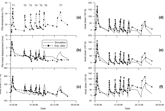
The results obtained from the test presented by Laloui et al. (2003) and the simulation results are shown in Figures 2 and 3. Seven heating/recovering cycles were applied; each cycle corresponds to a stage of the construction of the building. Figure 2a presents the change of mean temperature along the pile for each heating/recovering cycle. In Figure 2b, the pile head displacement during these cycles is presented. Pile axial strains measured at various depths are shown in Figures 2c-f. Comparison between the simulation and the experimental results shows that the mechanical behaviour of the pile can be predicted correctly not only in terms of pile head displacement but also in terms of axial strain at various depths.
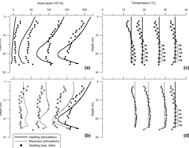
For further comparison, the axial strain profiles (measured and modelled) along the pile at the end of each heating (or recovering step) are shown for the first test (T1) where construction was not started yet (Figures 3a,b). In Figures 3c,d , temperatures measured and modelled along the pile are shown. Strain profiles show generally good agreement between the simulation and the measured ones, although in the actual test the behaviour seems rather reversible in the recovery phase. Discrepancies between simulation and experimental data can be explained partly by the difference in the temperature profiles. Localized deflections observed in both test and modelling results (Figures 3a,b) can be explained by the variability of soil properties with depth (Table 1).
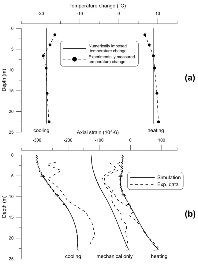
The results obtained from the tests presented by Bourne-Webb et al. (2009) are shown in Figures 4 and 5. During the test, the pile was first loaded to 1800 kN and unloaded afterwards. Reloading was performed up to 1200 kN. From the initial temperature (20°C), the pile was cooled with a circulating fluid at a temperature of about -2.5°C kept constant for about one month. Then the fluid was heated to about 36°C (Figure 4a). In Figure 5a, the temperature changes measured along the pile (as detailed in Bourne-Webb et al., 2009) are shown for the end of the cooling phase and the end of the subsequent heating phase. It is observed that the cooling phase decreased the average pile temperature by 18°C and that the pile temperature is 9°C higher than the initial one at the end of the heating phase. In Figure 4b, pile head displacement during different stages is shown. A good agreement between numerical and experimental results could be observed during mechanical and cooling steps while simulations overestimate pile head heave during heating. In Figure 5b, the axial strain profiles along the pile are plotted for three stages: end of the mechanical loading, end of the cooling, and end of the heating. Results recorded by strain gauges (after Amatya et al., 2012) during different phases are in good agreement with the simulation.
6
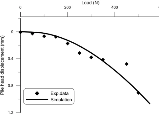
The load-settlement curve obtained from the work of Kalantidou et al. (2012) is shown in Figure 6. The results obtained during the heating/recovering tests under constant load are shown in Figure 7. As could be observed, without the pile head load (Figure 7a) the simulation is similar to the experimental results. That confirms that the pile head displacement corresponds to the thermal expansion of the pile as suggested by Kalantidou et al. (2012). Under 200 N of pile head load (Figure 7b), a large disparity between the two sets of curves could be observed. During the first heating, pile heave is about twice higher in the test. Besides, the pile behaviour seems more reversible compared to the numerical results. On the contrary, at 400 N and 500 N of pile head load (Figure 7c) a good compatibility could be found. It should be stressed that in 1g-physical models, stress levels are relatively low;; this increases experimental inaccuracies and modelling difficulties and could explain some of the discrepancies observed above.
4. Discussion
Mechanical behaviour of the energy pile is affected by the thermal volume change of pile and soil, soil and pile parameters changes due to temperature changes, and sensitivity of soil/pile interface characteristics to thermal loading (Laloui et al., 2006). In the present work, for the sake of simplicity, only the thermal volume change of pile is taken into account. This decoupling procedure was also used by Peron et al. (2012). The present study shows generally good agreement between experimental data and numerical simulation. That means the mechanical behaviour of the pile is mainly governed by its thermal volume change and the thermal volume change of soil has less influence. The disparity between experimental results and simulation could be explained first by the assumption that the temperature of the pile is homogenous. The second reason can be related to the lack of interface element in the numerical simulation and the third to the assumption of no thermal strain in the soil.
It is important to distinguish the „cooling‟ and „recovery‟ notions. In the experiments of Laloui et al. (2003) and also the mentioned small-scale test, the pile temperature decreases with time and not by imposing low temperatures directly. In other words the rate of temperature change is smaller in the recovery method, which is comparable to drained mechanical loadings in general. Time effects related to loading phases are not accounted for in our approach. That might be one source of the overestimation of irreversible deformations by the model in the recovery phase of Laloui et al. (2003). Other point is that application of thermal volume changes to the pile while no thermal volume changes are considered for the surrounding soil might induce a more abrupt response of the pile. In practice, in the presence of heat diffusion from the pile to the soil, the temperature field (and the consequent expansions or contractions) would be more uniform, which could lead to more uniform axial deformation distribution, as observed in the experiments presented by Laloui et al. (2003).
7
4. Conclusion
A commercial finite element code for geotechnical design was used for simulating a pile under thermo-mechanical loadings. An equivalent thermal volumetric deformation was applied to the pile. This simplified method was examined by simulating two in-situ tests on energy piles and one laboratory physical model test. The numerical results were compared to the ones measured during the experiments. The observations show that the simulations are in good agreement with the experiments.
At the observed scale, the proposed method seems to give satisfactory results in simulating the mechanical behaviour under coupled thermo-mechanical loadings. It could be used as a simple method in design procedures when fully coupled analyses methods are not envisioned.
Acknowledgements
The authors would like to acknowledge the French National Research Agency and the Ecole
des Ponts ParisTech, which collectively funded this project PiNRJ “Geotechnical aspects of
8
References
Amatya, B., Soga, K., Bourne-Webb, P., Amis, T., Laloui, L. (2012) Thermo-mechanical
behaviour of energy piles. Géotechnique 62, No. 6, 503–519.
Bourne-Webb, P., Amatya, B., Soga, K., Amis, T., Davidson, C., Payne, P. (2009) Energy pile test at Lambeth College, London: geotechnical and thermodynamic aspects of pile
response to heat cycles. Géotechnique 59, No. 3, 237–248.
De Gennaro, V., Frank, R., Said, I. (2008) Finite element analysis of model piles axially loaded in sands, Rivista Italiana di Geotechnica, No 2, 44-62.
Fromentin, A., Pahud, D., Laloui, L., Moreni, M. (1999) Pieux échangeurs: conception et règles de pré-dimensionnement. Revue Francaise de Génie civil, 3, No. 6, 387-421.
Kalantidou, A., Tang, A.M., Pereira, J.M., Hassen, G. (2012) Preliminary study on the
mechanicalbehaviour of heat exchanger pile in physical model. Géotechnique 62, No.11,
1047-1051. (http://dx.doi.org/10.1680/geot.11.T.013)
Karakus, M., Fowelle, R.J. (2005) Back analysis for tunnelling induced ground movements and stress redistribution. Tunnelling and Underground Space Technology 20, No. 6, 514-524.
Knellwolf, C., Peron, H., Laloui, L. (2011) Geotechnical analysis of heat exchanger piles. Journal of Geotechnical and Geoenvironmental Engineering 137, No. 10, 890-902.
Laloui, L., Moreini, M., Vulliet, L. (2003) Comportement d‟un pieu bi-fonction, fondation et
échangeur de chaleur. Canadian Geotechnical Journal 40, No. 2, 388 – 402.
Laloui, L., Nuth, M., Vulliet, L. (2006) Experimental and numerical investigation of the behaviour of a heat exchanger pile. International Journal for Numerical and Analytical Methods in
Geomechanics 30, No. 8, 763 – 781.
Nogami, T., Otani, J., Konagai, K., and Chen, H. (1992) Nonlinear soil-pile interaction model for
dynamic lateral motion. Journal of Geotechnical Engeneering 118, No. 1, 89–106.
Peron, H., Knellwolf, C., Laloui, L. (2011) A method for the geotechnical design of heat exchanger piles. Proc. Geo-Frontiers Conf., Jie H., Daniel E., Alzamora, P.E., ASTM, Geotechnical Special Publications (GSP) 211, 470-479.
Said, I (2004) Comportement des interfaces et modélisation des pieux sous charge axiale. PhD thesis, Ecole des Ponts ParisTech.
Suryatriyastuti, M.E., Mroueh, H., Burlon, S. (2012) Understanding the temperature-induced mechanical behaviour of energy pile foundations. Renewable and Sustainable Energy
Reviews 16, 3344– 3354.
Reeves, G.M., Sims, I., Cripps, J.C. (2006) Clay Materials Used in Construction. The Geological Society, Engineering Geology Special Publication. No. 21.
Yang, Z., Jeremić, B. (2005) Study of soil layering effects on lateral loading behavior of
9
Table captions
Table 1. Constitutive parameters of soils Table 2. Constitutive parameters of pile
Figure captions
Figure 1. Utilised mesh in the case of Laloui et al. (2003)
Figure 2. Tests presented by Laloui et al. (2003): (a) Pile temperature; (b) Pile head displacement; (c) Pile axial strain at 2.5-m depth; (d) Pile axial strain at 10.5-m depth; (e) Pile axial strain at 16.5- m depth; (f) Pile axial strain at 24.5-m depth.Figure 3. Slab panel sizes Figure 3. Test T1 presented by Laloui et al. (2003): (a) Pile axial strain distribution during heating; (b) Pile axial strain distribution during recovering; (c) Temperature evolution of pile during heating; (d) Temperature evolution of pile during recovering.
Figure 4. Test presented by Bourne-Webb et al. (2009): (a) Temperature applied to the pile; (b) Pile head displacement.
Figure 5. Test presented by Bourne-Webb et al. (2009): (a) Profile of temperature along the pile; (b) Pile axial strain distribution.
Figure 6. Tests presented by Kalantidou et al. (2012): load-settlement curve.
Figure 7. Tests presented by Kalantidou et al. (2012): Temperature-settlement curves under different head loads.
10
Table 1. Constitutive parameters of soils
Case
study
Material
Depth
(m)
Drainage
condition
γ
(
kN
m
3)
c
(kP
a)
φ (°)
Ψ
(°)
E
(MPa)
Laloui et
al. 2003
Alluvial soil
0-5.5
Drained
20
5
30
0
260
0.3
0
Alluvial soil
5.5-12
Drained
19.5
3
27
0
260
0.3
0
Sandy gravelly
moraine
12-21.7
Drained
20
6
23
0
450
0.3
5
Bottom
moraine
21.7-25.1
Drained
22
20
27
0
630
0.3
5
Molasse
25.1-31
Undrained
25.5
4
25
0
3000
0.2
2
Bourne-Webb et
al. 2009
Made ground
(sand and
gravel)
0-4
Drained
19
0
35
0
13
0.3
0
London clay
> 4
Undrained
20
20
25
0
70
0.3
0
Kalantidou
et al. 2012
Fontainebleau
sand
0-0.85
Drained
15.1
0
36.5
0
340
0.3
0
11
Table 2. Constitutive parameters of pile
Pile characteristics
Pile
diameter
(m)
E (GPa)
α (
610
/°C)
Laloui et al. (1999)
1.000
29.2
0.20
30.0
Bourne-Webb et al.
(2009)
0.550
40.0
0.20
25.5
Kalantidou et al. (2012)
0.020
13.0
0.33
66.0
12
Figure 1. Utilised mesh in the case of Laloui et al. (2003)
13
Date -100 0 100 200 300 A x ia l s tr a in ( 1 0 ^ -6 ) 0 50 100 150 200 A x ia l s tra in ( 1 0 ^ -6 ) 0 50 100 150 200 A x ia l s tr a in (1 0 ^ -6 ) Date -40 0 40 80 120 160 200 A x ia l s tr a in (1 0 ^ -6 ) 10 20 30 40 P ile t e m p e ra tu re ( °C ) -2 0 2 4 P ile h e a d d is p la c e m e n t (m m ) Simulation Exp. data (a) (b) (c) 14.05.98 01.09.98 20.12.98 09.04.99 14.05.98 01.09.98 20.12.98 09.04.99 T1 T2 T3 T4 T5 T6 T7 (d) (e) (f)Figure 2. Tests presented by Laloui et al. (2003): (a) Pile temperature; (b) Pile head
displacement; (c) Pile axial strain at 2.5-m depth; (d) Pile axial strain at 10.5-m depth;
(e) Pile axial strain at 16.5- m depth; (f) Pile axial strain at 24.5-m depth.
14
0 50 100 150 200 Axial strain (10^-6) 30 20 10 0 D e p th ( m ) 30 20 10 0 D e p th ( m ) Heating (simulation) Recovery (simulation) Heating (exp. data) Recovery (exp. data)0 10 20 30 40 Temperature (°C) 30 20 10 0 D e p th ( m ) 30 20 10 0 D e p th ( m ) (a) (b) (c) (d)
Figure 3. Test T1 presented by Laloui et al. (2003): (a) Pile axial strain distribution
during heating; (b) Pile axial strain distribution during
recovering; (c) Temperature
evolution of pile during heating; (d) Temperature evolution of pile during
recovering.
15
Date -6 -4 -2 0 P ile h e a d d is p la c e m e n t ( m m ) Exp. data Simulation
9 Jun 23 Jun 7 Jul 21 Jul 4 Aug
loaded to 1800 kN cooling heating
-10 0 10 20 30 40 T e m p e ra tu re ( °C
) loading to 1800 kN and unloading
end of heating end of cooling
(a)
(b)
unloaded to 0 kN reloaded to 1200 kN reloaded to 1200 kNFigure 4. Test presented by Bourne-Webb et al. (2009): (a) Temperature of the
circulating fluid; (b) Pile head displacement.
16
-300 -200 -100 0 100Axial strain (10^-6)
25 20 15 10 5 0D
e
p
th
(
m
)
Simulation
Exp. data
cooling mechanical only heating
-20 -10 0 10
Temperature change (°C)
25 20 15 10 5 0D
e
p
th
(
m
)
Numerically imposed temperature change Experimentally measured temperature changecooling heating
(a)
(b)
Figure 5. Test presented by Bourne-Webb et al. (2009): (a) Profile of temperature
along the pile; (b) Pile axial strain distribution.
17
0 200 400 600 Load (N) 1.2 0.8 0.4 0 P ile h e a d d is p la c e m e n t (m m ) Exp.data SimulationFigure 6. Tests presented by Kalantidou et al. (2012): load-settlement curve.
0 -0.1 -0.2 -0.3 -0.4 P ile h e a d se tt le m e n t (m m )
First cycle- Exp. data Second cycle- Exp. data First cycle- Simulation Second cycle- Simulation
0 10 20 30 Temperature change (°C) 0.4 0.2 0 -0.2 -0.4 P ile h e a d se tt le m e n t (m m) 0.6 0.4 0.2 0 -0.2 -0.4 P ile h e a d se tt le m e n t (m m ) 0 10 20 30 Temperature change (°C) 0.6 0.4 0.2 0 -0.2 -0.4 P ile h e a d se tt le m e n t (m m) (a) (b) (c) (d)