Space-charge compensation of highly charged
ion beam from laser ion source
By S.A. KONDRASHEV,* J. COLLIER,t
AND T. R. SHERWOODt
* Institute for Theoretical and Experimental Physics, 117259 Moscow, Russia tCERN, 1211 Geneva, Switzerland
(Received 2 April 1996; accepted 17 April 1996)
The problem of matching an ion beam delivered by a high-intensity ion source with an accel-erator is considered. The experimental results of highly charged ion beam transport with space-charge compensation by electrons are presented. A tungsten thermionic cathode is used as a source of electrons for beam compensation. An increase of ion beam current den-sity by a factor of 25 is obtained as a result of space-charge compensation at a distance of 3 m from the extraction system. The process of ion beam space-charge compensation, requirements for a source of electrons, and the influence of recombination losses in a space-charge-compensated ion beam are discussed.
1. Introduction
The difficulty in matching high-intensity ion beams from ion sources to a subsequent accelerator structure increases when the beam energy is low because of the effects of space-charge forces. The matching section usually includes some combination of electrostatic and magnetic lenses. Increasing the extraction potential may be required (Brown et al. 1989). In the case of a laser ion source, which produces highly charged heavy ions, the typical ion current can easily reach 1 A (Sharkov et al. 1992) with ion current densities, j > 10 mA/cm2. Compensation of the ion beam space-charge by injecting electrons can help to solve this problem (Evans & Warner 1971).
This paper describes an experimental investigation of the space-charge compensation of an ion beam, extracted from a laser-produced plasma, and its transport over a distance of 3 m.
2. Experiments
Ion beam space-charge compensation is achieved by injecting electrons that reduce the ion space-charge density throughout the beam. The electron energy spread should be as small as possible, and the electron velocity along the ion beam direction should be approx-imately the same as the ion velocity. The electrons should be injected as close as possible to the output electrode of the extraction system and over a time at least as long as the dura-tion of the ion current pulse. One source of electrons is a thermionic cathode. Pure tung-sten cathodes can give electron current densities up to 14 A/cm2 with continuous operation over several tens of hours (Grigorev & Meylihov 1991).
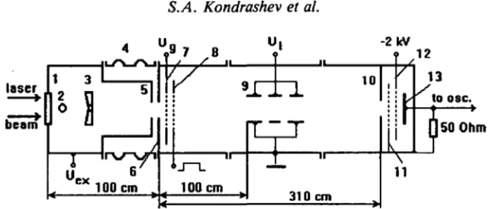
The arrangement used for the experiments is shown in figure 1. Shown in the figure are (1) the sodium chloride vacuum window that passes the infra-red beam from a TEA CO2
laser; (2) the target, which is a tantalum cylinder, 30 mm in diameter, that can be rotated around a vertical axis from outside the tank; (3) a focusing mirror; (4) an insulating tube © 1996 Cambridge University Press 0263-0346/96 $11.00 + .10
laser -2kV 10 12 310 cm \ 13 to 08C. (150 Ohm 11
FIGURE 1. Experimental layout. 1 -NaCl window, 2—target, 3-focusing mirror, 4-insulating tube, 5 and 6-extraction electrodes, 7-negative potential grid, 8 —thermionic cathode, 9-electrostatic lens, 10-input aperture of collector, 11 and 12-grids, 13—copper plate.
between the target chamber and the extraction chamber; (5) and (6) the extraction electrodes; the electrode (7) is at a negative potential, and the target chamber is at +50 kV (the aper-ture of the extraction system is 3 cm); (8) the thermionic cathode; downstream of the extrac-tion tank is an electrostatic lens (9) and a Faraday cup to measure the ion current (Amdidouche et al. 1992); the Faraday cup includes the aperture (10), two grids (11), (12), and a copper plate (13). A laser power density of 2-1012 J-cm~2 can be obtained at the target.
The electron source consists of a thermionic cathode in the form of a 200-/*m diameter tungsten wire together with a negative grid positioned between the extraction system and the cathode. Two configurations of the heated wire were used and are shown in figure 2. The two configurations give different electron density distributions. For the first, figure 2a, the distribution is approximately uniform, and the potential difference between the neigh-boring elements of the wire gives a component of the electric field perpendicular to the beam direction at the thermionic cathode structure. This field gives rise to electron velocities cor-responding to an energy of about 10 eV, with a considerable variation over the ion beam cross section. For the second configuration, figure 2b, the electron density was peaked with a maximum on the ion beam axis while the electron velocities perpendicular to the axis were lower and had a smaller spread over the ion beam cross section.
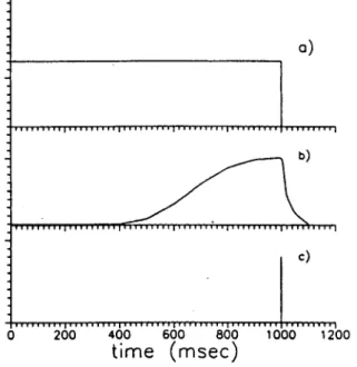
The wires were heated with a pulsed-current generator for 1 s. This period was deter-mined by the time required for the cathode to reach a steady emission rate. Pulse shapes for the heating current, thermionic current, and the laser trigger are shown in figure 3.
a]
J L 7 * 9 Amp. -45 V
b]
J L 20 Amp.-20 V
a)
c)
200 400 600 800 1000
time (msec)
1200
FIGURE 3. (a) Heating current, (b) thermionic current, and (c) laser trigger.
The role of the negative grid near the electron emitter is to prevent electrons from return-ing to the extraction region. The grids placed in front of the Faraday cup prevent electrons, arriving with the ions, from entering the collector as well as trapping secondary electrons generated inside the cup. Since the grid transparency is high, the secondary electrons from the grid nearest the final collector can be neglected.
The Faraday cup first was placed directly following the extraction system, and the mea-sured ion current is shown in figure 4. The ion beam contains many charge states. Accord-ing to time-of-flight analyses of the charge states and energies (Amdidouche et al. 1992), the 100-mA current shown for the first spike is due to highly charged ions with an average charge state, Z = 20, corresponding to a current density, j > 10 mA-cm"2.
The Faraday cup then was positioned as in figure 1. The current first was maximized by varying the spacing between the extraction electrodes, within a range of 0.5 to 5.5 cm, keep-ing the extraction voltage constant. The current for the first spike, which is for ions with the higher charge states, was larger with the spacing between 4 and 5 cm, while the cur-rent at later times was reduced. This can be explained by the peculiarities of ion beam extrac-tion from plasma when there is a wide range of charges and energies. A value for the gap spacing of 4 cm was chosen for the rest of the experiments.
The negative grid potential was varied in the range zero to —2 kV. Transmission for the high-charge-state ions improved as the grid potential was moved away from zero, with the best results being obtained in the range of - 1 to - 2 kV.
The potential of the electrostatic lens was changed over a range zero to +30 kV. The trans-port of ions was optimal with the electrostatic lens potential at 20 kV.
Ion current signals from the Faraday cup are shown in figures 5 and 6. In figure 5, the thermionic source is off, while in figure 6 it is on.
The ion currents for the higher charge state ions, averaged over several series of mea-surements, with different settings for the transport elements (thermionic cathode, electro-static lens, and negative potential grid), are presented in table 1. Here, the first column
TBC Running: Waiting for Trigger
Ch2Zoom: O.SXVert LOXHorz
4.00 Ch3 40.0ITIV
«' Aiix SL - i . z s v
FIGURE 4. Faraday cup signal at the exit of the extraction system (channel no. 1).
indicates the potential on the negative grid, the second indicates whether or not the ode is heated, the third gives the electrostatic lens potential, the fourth indicates the cath-ode used, and the fifth contains the current measured in the Faraday cup.
As can be seen, the best transport for high charge state ions is obtained with ion beam space-charge compensation. An increase in ion beam current, by a factor of 5, is gained with the first heated wire configuration (figure 2a), while a factor of 25 is obtained with
TBK Stopped: 1 Acquisitions
MS. OO|JS A U X I ^ST
T6K stopped: 1 Acquisitions
H
b'omb ill l o o p s Aux'y '-i.b'dv
FIGURE 6. Ion current signal with compensation.
the second configuration (figure 2b). The negative potential on the grid improves the beam transport for the higher charge state ions by a factor of 3.
The utility of the electrostatic lens is more difficult to quantify. Its effect with space-charge compensation is due to the combination of its ability to focus the beam while at the same time interfering with the transport of electrons past it. When it is on, it improves the ion beam transport compared with that of the uncompensated beam; but, for the second configuration, the best result is obtained with the lens turned off. It should be noted, in this case, that it was necessary to allow an interval of a few minutes between laser shots in order to obtain stable operation. This would seem to be connected with the slow cool-ing of a thermionic cathode in the vacuum, which results in a nonreproducible tempera-ture profile along the length of the heated wire, with resultant changes to the electron density distribution over the ion beam cross section.
TABLE 1. High-charge-state ion currents for different transport element settings tA.kV Heating Cathode /, mA
0 0 0 0 0 +20 +20 +20 +20 1 & 1 & 1 2 1 & 1 & 1 2 2 2 2 2 0.2 0.6 1.0 5.0 0.6 0.8 1.2 1.5
3. Process of ion beam space-charge compensation
The space-charge force for the neutralized beam can be estimated in the following way. In the electrostatic limit, the electric potential in a beam of charged particles can be found by solving the Poisson equation (Gabovich 1972). For a cylindrical beam with a uniform charge density, that is otherwise in free space, the. potential change with radius can be writ-ten as:
-i
R2
U(R) - U(0) = Erdr = po/?2/(4eo), (1) Jo
where r is the radial coordinate, R is the radial position in the beam, and p0 is the charge
density. Here, variations along z, the longitudinal coordinate, have been neglected. Taking into account the relation for the total ion beam current, /:
I = Jz ^ro = Po vz w02, (2)
where r0 is the beam radius.
The expression for the radial potential well is
C/(r
o)-£/(O)=//(4T.ive
o) (3)
or
(4)
where vz = V2£',/M,-, Et is the ion energy, and M, is the ion mass. If the ion energy is
measured in electron volts and the mass in a.m.u., this becomes
(t/(r0)-1/(0)) = 6.5 • 1 05- / - V M 7 £ 7 . (5) An ion bunch creates a 3D potential well for electrons, the depth being defined in the above equations. Electrons can be captured in this well and moved with the ion bunch, com-pensating its space charge field.
If the thermal velocities of the electrons are sufficiently high, some electrons will leave the trap and there will be only a partial compensation. The minimum value of the residual uncompensated potential can be estimated, according to Gabovich et al. (1971), as:
(6) where / is the total current of ion beam, v, is the ion velocity, and Te is the electron
temperature.
An uncompensated ion beam, with the ions initially moving in parallel paths, diverges due to the beam's radial electric field. The distance / for which the beam radius goes from r0 to r for an ion group with average charge state Z is given by Gabovich (1972):
1
/(/•//•„) = 88 • (M,/we) 1/4/1/2 U-xi/4(l/r0) • ^ ^ , (7)
where M, is the ion mass, me is the electron mass, / is the total current of ion beam, Uex
is the extraction voltage, r0 is the initial radius of ion beam, r is the radius of ion beam
The average charge state for the ion group under consideration is defined as:
z = ^r>
(8)
where Iz is the current for charge state Z. Equation (7) is valid if the ion energy is given
by the expression Ez = Z-Uex. We now apply these results to the ion beam used in the
experiments.
Using this equation with the following parameters for a beam of tantalum ions viz. / = 110 mA, Z ~ 20 (Amdidouche et al. 1992), Uex = 50 kV, Af, = 181 a.m.u., r0 = 1.5 cm,
and / = 310 cm, the value 20 is found for f(r/r0); from a table of this function, the ratio
r/r0 is approximately 70. It therefore would be expected that the ratio of the currents in
the Faraday cup and that extracted should be 2-10~4. However, experimentally this value was found to be 2-10~3. The difference between the experimental and calculated values can be attributed partly to the initial beam focusing during extraction and by the partial compensation of ion beam space charge by electrons released from the electrode or cre-ated by collisions with molecules of the residual gas.
We can estimate the depth of the potential well for an uncompensated ion beam from equation (5), where Et is replaced by the average ion energy, if, = Z- Uex.
We consider the first peak of the ion beam current. This is known to have an average charge state of approximately 20 (Amdidouche et al. 1992). Then, U(r0) - U(0) = 1 kV
for Z = 20 and I2 ~ 110 mA. It follows that the grid shielding the extracting system from electrons must be at a negative potential, Ug < - 1 kV.
We can use equation (6) to estimate the minimum value of the residual uncompensated potential well as defined by the electron velocity spread. The tungsten thermionic cathode surface needs a temperature of 2700 K (Grigorev & Meylihov 1991) to produce a therm-ionic current density of 1 A-cm"2, about the current used in the experiments. This corre-sponds to an electron temperature of 0.2 eV and gives a value of approximately 20 eV for A £/„,,„. This is equivalent to the potential well for an uncompensated ion current of Imin = 2.3 mA. Using equation (7) again we find that such a beam would have an increase
in radius by a factor of 6.5, and that the ratio of Faraday cup and extracted currents would be approximately 2• 10~3, compared with the measured value of 5 • 10~2. Some discrepancy between the experimental and estimated values is to be expected, as was explained earlier.
The influence of the negative potential grid on the spreading of the ion beam in the absence of the injected electrons is well known (Wolf et al. 1992). It is related to the pres-ence of electrons coming from the vacuum chamber walls and the residual gas. These elec-trons flow into the extraction system and leave the ion beam if there is no negative potential on the grid; otherwise, they are captured by the ion beam electric field, partially compen-sating its space charge and decreasing the spreading of the ion beam.
4. Requirements of a source of electrons for effective space-charge compensation
From the above results we can determine some of the properties of an electron source for achieving good space-charge compensation. As can be seen from equation (6), the elec-trons should have a low temperature. Secondary elecelec-trons emitted by ion impact on solid surfaces have effective temperatures greater than a few eV (Kaminsky 1967) and therefore should not be expected to lead to a high degree of compensation.
The source should supply electrons with low velocities in the radial direction and veloc-ities in the longitudinal direction nearly equal to the ion velocity. For tantalum ions with
an average charge state « 20 and extracted at 50 kV, the appropriate longitudinal velocity corresponds to an electron energy of 3 eV.
Furthermore, there is the question of the timing of the electron emission with respect to the arrival of the ion beam. In the experiments described here, the thermionic cathode emits electrons before the arrival of the ions at the cathode. This could lead to undesir-able oscillations of electrons along the ion beam axis. However, the potential changes of the thermionic cathode over the ion beam cross section are small (~10 eV), and they do not give a large electron energy spread on the ion beam cross section. It would be possible to heat the cathode for a period of about that of the ion beam pulse duration and timed so that the ion beam passed the cathode while it was emitting (Henkelmann et al. 1991). This would reduce undesirable oscillations of the electrons along the ion beam axis. How-ever, the potential variation along the thermionic cathode in this case will be a few hun-dred volts and could lead to an undesirably large electron energy spread over the ion beam cross section. The best system could be decided by further experiments. Problems arise in the experiments described here because there are changes that occur in the beam potential as it spreads, and as a result of further electrons coming from the electrodes and walls, the apertures and walls of the vacuum chamber due to ions being lost on them.
The possibility of using a space-charge compensation system for matching a laser ion source to an operational accelerators (Haseroth 1990) requires the development of a therm-ionic cathode that is capable of operating with a repetition rate of about 1 Hz and pro-ducing an ion beam with stable properties.
5. Recombination losses of ions in the space-charge compensated beam
A further effect that might need to be considered is ion recombination due to the pres-ence of the electrons. Let us estimate the rates of the recombination processes for the con-sidered ion beam. One can consider a reasonable approximation: The ion beam with a high compensation degree is considered as a quiescent plasma with electron temperature Te.
This means that we neglect the relative motion of the electron and ion components, and all processes inside the beam are defined by electron temperature only.
1. Dielectronic recombination (Burgess 1964; Latyshev & Rudskoy 1987):
J?
d«6-lO-
l o 7 V | i ZJ
ze-**
T- [cm^c-
1],
1 e
where Nz is the number of bounding electrons, iz is the ionization potential of an
ion with charge state Z in eV, and Te is the electron temperature in eV.
For ions Ta+20: Nz ~ 10, 5Z = 526 eV and for Te « 0.2 eV:
/?d«10-1 0 0 0 [cm3-c-'];
it is negligible. Rd will be maximum for Te=\3z. RTx{Te = f #z) * 3" 10~5 [cm3 -c~'].
2. Photorecombination (Mcwirter 1967):
~ " • " - "Pn T-M Z' [cm3-c-']. For ions Ta+20:
3. Three-body recombination (Gurevich & Pitaevsky 1964):
2 6
f S [cm
3-c-'].
For high compensation degree ne ~ Znh
Let us consider the most "dangerous" case for the recombination losses of highly charged ions. We will assume that the density of particles in the ion beam with space-charge compensation does not decrease during the time of its spreading.
The current density of ion beam:
j = - = 1(T2 A/cm2 (/ = 0.1 A; r = 1.5 cm) j = n,eZVi
Vi= /—- = 108 cm/c (£, = ZeUex = 1 MeV, MTa = 181 a.m.u.)
"\ M
n,= -J— = 3 - 1 07c m -3. eZV
Then, R,h~ 8-10"12 c m ^ c "1.
4. Let us define the rate of recombination for which the considerable part of ions (with charge state Z) (=50%) will change its charge state to Z - 1:
N, « nrVtf,
where Nr is the total number of recombined ions with charge state Z, nr is the
num-ber of recombined ions with charge state Z in the unit volume for unit time, V is the "volume" of the ion beam in space, and tj is the time of flight of ions with charge state Z in the beam with space-charge compensation:
nr = Rriitie,
where R is the recombination rate for ions with charge state Z, and /i,-, ne are the
densities of ions and electrons.
The total number of ions Ta+20 in the beam:
Nz " Ij7TZ-e1 « 1-7 • 1010 (/ « 100 mA, At - 0.5 /xs).
Let us consider the most "dangerous" case for the recombination losses of highly charged ions. We will consider that the density of particles in the ion beam with space-charge com-pensation does not decrease during the time of its spreading. Then the "volume" of the ion beam in a space is
Vz = SzvzAtz » 4-10-4 m3 lvz * 108 — , r • 1.5 cm, Atz » 0.5
and the time of flight of ions to the Faradey cup is
/>=-^=3/iS (V = 3m, v
z~10
6-};
v
zV c /
The rate of recombination for ions with a charge state Z, for which one-half of the ions will recombine, is
/
?
4
5 1 0
.
Znf c
R<t> ^p/i. Rih *^ ^ ° ; obviously, the essential recombination losses of highly charged ions do not take place for ion beams with space-charge compensation by thermoelectrons.
We considered the ion beam with a high compensation degree as a quiescent plasma and assumed that all processes inside the beam are defined by the electron temperature only. Of course, the situation might be more complicated for a real impulse ion beam. However, the rates of all recombination processes (except dielectronic recombination) decrease with increasing electron and ion relative velocities. The rate of dielectronic recombination also is estimated for a maximum value. Therefore, all estimations are the upper limits for the recombination rates.
Finally, the influence of the recombination losses in space-charge-compensated ion beams has to be investigated in special experiments.
We can summarize the discussion by referring to the following points that relate to im-provements for future experiments:
1. Improve the construction of the thermionic cathode so as to give a better uniformity of the electron density and energies, in the range of 1 to 10 eV, at the cathode. 2. Determine the effect on beam spreading with different rates of heating of the
therm-ionic cathode.
3. Determine the possibility of recombination losses.
4. Measure ion beam emittance with space-charge compensation.
5. Determine changes in ion beam density in the focal plane of the extraction system with space-charge compensation.
6. Conclusions
The process of ion beam space-charge compensation by injecting low-energy thermal elec-trons has been considered. It is shown that the pure tungsten thermionic cathode satisfies all of the basic requirements of the source of electrons for effective space-charge compen-sation of the ion beams obtained at the exits of different sources, including the laser ion source. Ion beam transport with space-charge compensation by thermoelectrons seems to show better results compared with the case of compensation by secondary electrons com-ing from the walls of the vacuum chamber due to ion impact. An increase of ion beam cur-rent density by a factor of 25 is obtained as a result of space-charge compensation by thermoelectrons at the distance of 3 m from the extraction system for the laser source of highly charged Ta ions. The estimations of the recombination rates for three-body, photo-and dielectronic processes that they cause negligible recombination losses of ions in the beams with space-charge compensation by thermoelectrons.
Acknowledgments
The authors wish to express their thanks to Dr. H. Haseroth and Dr. B. Yu. Sharkov for encouragements to this work. They also would like to thank Mr. K. Langbein, Mr. A. Kuttenberger, and Mr. O. Shamaev, for their assistance in the preparation of the experi-ments, and Mr. S. Savin, for the creation of the electronic devices and assistance in pre-paring the experiments. This work was financially supported by the Russian Fund of
Fundamental Research No. 94-02-05942-a and NATO International Scientific Research Grant No. 921324.
R E F E R E N C E S
AMDIDOUCHE, Y. et al. 1992 CERN Technical Report PS 92-08(HI).
BROWN, I.G. 1989 Physics and Technology of Ion Sources (John Wiley, New York).
BURGESS, A. 1964 Astrophys. J. 139, 776.
EVANS, L.R. & WARNER, D.J. 1971 IEEE Trans. Nucl. Sci. 18, 1068. GABOVICH, M.D. et al. 1971 Ukrainskii fizicheskii zhurnal 16, 812.
GABOVICH, M.D. 1972 Physics and Techniques of Plasma Ion Sources (Energoizdat, Moscow). GRIGOREV, I.S. & MEYUHOV, E.Z. 1991 Physical Values (Energoizdat, Moscow).
GUREVICH, A.V. & PITAEVSKY, L.A. 1964 Zhurnal experimentalnoy i theoreticheskoy fiziki 46, 1281. HASEROTH, H. et al. 1990 CERN Technical Report 90-01.
HENKELMANN, T. et al. 1991 Nucl. Instrum. Meth. B 56/57, 1152.
KAMINSKY, M. 1967 Atom and Ion Collisions at Metal Surfaces (Mir, Moscow). LATYSHEV, S.V. & RUDSKOY, I.V. 1987 ITEP Preprint 120, Moscow.
MCWIRTER, R. 1967 Plasma Diagnostics, R. Hadlstoon and S.M: Leonard, eds. (Mir, Moscow).
SHARKOV, B . Y U . et al. 1992 RSI 63(4), 2841.