Development of a Bi-Layer Mineralized Bone and Cartilage Regeneration Template
by
Cassandra Holzgartner Ott B.E., Engineering Science
State University of New York at Stony Brook, 2004
Submitted to the Department of Materials Science and Engineering in Partial Fulfillment of the Requirements for the degree of Master of Engineering in Materials Science and Engineering
at the
Massachusetts Institute of Technology September 2005
C 2005 Massachusetts Institute of Technology All Rights Reserved
Signature
of Author... ... ...
...
Department of Materials Science and Engineering August 4, 2005
Certified
by .
...
...
..
...
Loma J. Gibson Matoula S. Salapatas Professor of Materials Science and Engineering, Professor of Mechanical Engineering and Professor of Civil and Environmental Engineering
Thesis Supervisor
Accepted
by ...
...
...
Gerbrand Ceder R.P. Simmons Professor of Materials Science & Engineering
Chair. Departmental Committee on Graduate Students
MASSACHUSETTS INSTITUTE OF TECHNOLOGY
Development of a Bi-Layer Mineralized Bone and Cartilage Regeneration Template
by
Cassandra Holzgartner Ott
Submitted to the Department of Materials Science and Engineering On August 4, 2005 in partial fulfillment of the
Requirements for the degree of Master of Engineering in Materials Science and Engineering
ABSTRACT
Porous collagen-glycosaminoglycan (CG) scaffolds have been studied extensively and proven to be capable of tissue regeneration in vivo for applications including skin regeneration templates, hollow nerve guides and conjunctiva regeneration. While the current CG scaffold has been thoroughly examined both mechanically and clinically, it has yet to prove appropriate for load-bearing applications. This study will investigate the mechanical properties of a mineralized CG scaffold and its application potential in a load-bearing environment. Through the introduction of calcium-phosphate mineral into the standard CG formulation the matrix analog will be available for bone regeneration. Utilizing a patented triple co-precipitation technique developed at Massachusetts Institute of Technology and Cambridge University, a homogenous mineralized scaffold will be manufactured. Comparison to healthy trabecular bone as well as the selection of the most appropriate extracellular matrix analog will be presented.
The key to commercial success is the introduction of a bi-layer bone and cartilage regeneration template to address concerns and difficulties in cartilage repair today. This dual combination is termed a layered osteochondral scaffold. The commercial viability of this product as well as the company founded on its inception, OrthoCaP, Inc., is delivered as a start-up venture over the next eight to ten years. With several key patents already filed, an extensive patent search was completed to establish leading competitors and technology in the marketplace. Although still in the primary phases of development, short-term profitability can be seen through licensing the technology to larger more secure firms. Long-term profitability is realized through a more scientific approach of broadening the technology to other areas of tissue regeneration and modifying the mechanical and material characteristics associated with collagen based templates.
Thesis Supervisor: Lorna J. Gibson
Title: Matoula S. Salapatas Professor of Materials Science and Engineering, Professor of Mechanical Engineering and Professor of Civil and Environmental Engineering
TABLE OF CONTENTS
I INTRODUCTION 5
1.1 NATURAL BONE REGENERATION 5
1.2 ARTICULAR & MENISCAL CARTILAGE 8
1 .3 THE PROBLEM 9
1 4 THE SOLUTION 10
2 INTELLECTUAL PROPERTY & PATENT FILING 12
2.1 IP STUDY 13
2.1.1 AREAS OF AjP PLICATION 13
2.1.2 PATENT SEARCH 14
2.1.3 SPECIFIC FINDINGS IN AREAS OF APPLICATION 14
2.1.4 IMPACT ON MINERALIZED BONE SCAFFOLDS 19
2.2 PATENT FILING PROCESS 19
2.2.1 PUBLIC DOMAIN 21
2.3 LAYERED OSTEOCHONDRAL SCAFFOLD PATENT 22
3 FULL-SCALE MANUFACTURING OF LAYERED OSTEOCHONDRAL SCAFFOLDS 24
3.1 LYOPHILIZATION 24
3.2 TRIPLE COPRECIPITATION METHOD 25
3.3 QUANTITATIVE ANALYSIS OF MANUFACTURING PROCESS 26
3.3 1 LYOPHILIZAT;[ON 27
3.3.2 TRIPLE CO-PRECIPITATION METHOD 37
3.4 CONTROL OF DEGRADABILITY 48
3. 5 MECHANICAL PROPERTIES 51
3. 5.1 COMPRESSION TESTING DATA 51
3. 5.2 COMPARISON TO NATURAL TRABECULAR BONE 59
4 BUSINESS MODEL: ORTHOCAP, INC 63
4. 1 MARKET ANALYSIS 63
4. 1.1 CURRENT VA1.UE OF ORTHOBIOLOGICS MARKET 66
4. 1.2 PRODUCTION VOLUME & VALUE 68
4.1.3 COMPETITION & MARKET STRATEGY 68
4. 1.4 PUBLICLY TRADED COMPANIES 68
4.2 BUSINESS DESCRIPTION: ORTHOCAP, INC. 73
4.3 MANAGEMENT 74
4.4 COST MODEL & FINANCIAL 75
5 6 7 CONCLUSION 81 REFERENCES 82 APPENDIX A 85
1 Introduction
According to the Center for Disease Control, arthritis and chronic joint symptoms affect nearly 70 million Americans, or about one of every three adults, making it one of the most prevalent diseases in the United States. As the population ages, this number will increase dramatically. Besides being the leading cause of disability in the United States, it leads to economic loses totaling over $82 billion annually.' Current research has successfully developed novel technologies involving polymeric scaffolds to aid in the regeneration of tissues such as articular and meniscal cartilage, diseased bone and severed peripheral nerves. Armed with this published information as well as a new layered osteochondral scaffold developed at Massachusetts Institute of Technology and Cambridge University, exploration into regenerated bone and meniscal cartilage by cell proliferation and scaffold mechanics will be addressed.2'3
The layered osteochondral scaffold represents the debut product from the start-up venture OrthoCaP, Inc. In addition to addressing the physiological requirements of the scaffold a complete patent search and manufacturing plan are discussed. An introductory business model and cost model are introduced at the end of this study to justify the time and effort invested in the commercialization of this technology. Although hypothetically profitable there are many trials in the research and development stage to conquer before FDA approval can be sought and full-scale manufacturing can begin.
1.1 Natural Bone Regeneration
Bone is a dynamic tissue that is constantly being resorbed and reformed by a particular group of cells in the body. There are three distinct ways that bone can be modified: osteogenesis, modeling and remodeling. These can differ depending on the person's age, type of bone being generated as well as the size of the defect or remodeling site. The layered osteochondral scaffold discussed in this study will support the regeneration of bone through the modeling process. After full degradation of the layered osteochondral scaffold, normal remodeling will occur as the body monitors the new bone tissue.
bone, the Haversian, the inner surface of the Haversian canals, and the trabecular bone surface. Each of these surfaces can be modified. Figure 1 shows the structure of a long bone. The layered osteochondral scaffold will be implanted adjacent to healthy trabecular bone in order to take advantage of the ample supply of nutrients and bone remodeling cells present along the inner section of bone known as the marrow.
Compact bone Osteon
lae
Figure 1 Long bone structure.
(Reproduced from Mow, 2004, Basic Orthopaedic Biomechanics & Mechano-Biology, 3rd Edition, Lippincott, Williams & Wilkins)
An embryo develops bone through the modification process of osteogenesis. This is the formation of bone on soft tissues, either fibrous tissue or cartilage. This process also occurs with the fracture of bones during adolescence. There are two sub-classes of osteogenesis: intramembraneous and endochondral ossification. Intramembraneous ossification occurs for flat bones such as the skull and mandible and does not readily apply to the goals of the layered osteochondral scaffold. Endochondral ossification is different from intramembraneous because it occurs where there is a cartilage base. Embryonic bones begin as cartilaginous tissue. This ossification process is responsible for long bone and vertebrae formation.
Endochondral ossification is comprised of 4 steps, each of which is outlined pictorially in Figure 2.4
1. Fig. 2.A: Swelling of the chondrocytes occurs; chondrocytes cease the production of Type II collagen and proteoglycan aggregates; chondrocytes begin production of Type X (ten) collagen and alkaline phosphates that will result in a matrix vesicle in which the chondrocytes will die.
2. Fig. 2.B: The cartilage matrix begins to calcify and harden; with the limited permeability of the new matrix oxygen, nutrients and waste cannot diffuse resulting in chondrocytes degeneration and death.
3. Fig. 2.C: Blood vessel invasion by a periosteal bud of blood vessels that penetrates the primary marrow cavity through the bone collar formed in step 1.
4. Fig. 2.D: A new bone matrix is laid down on the scaffolding provided by the calcified cartilage; osteoblasts formed from the periosteal bud.
(A) (B)
(C) (D)
Figure 2 Endochondral Ossification (Fig D: OB = osteoblasts, OC = osteoclasts, CC = calcified cartilage, Oc =
osteocytes)
(Reproduced from Mow, 2004, Basic Orthopaedic Biomechanics & Mechano-Biology, 3"dEdition, Lippincott, Williams & Wilkins)
During osteogenesis osteoblasts and osteoclasts are not connected in any way. They act independently from one another and are not controlled by a coupled feedback loop.
Bone modeling is the modification process most relevant to the success of the layered osteochondral scaffold. Because the calcified scaffold is provided at the implantation site osteoblasts cells need only relocate to this new region and begin depositing new bone. The key
part of this implantation is providing a blood supply and nutrients to the site. Necessary cells will be delivered with an adequate blood supply. This is achieved by performing a subchondral drill into the soft tissue of the bone. The soft tissue, or bone marrow, has an abundant blood supply and will be the resource during bone modeling.
Modeling is a way of depositing large amounts of healthy new bone. Again, as with ossification, osteoblasts and osteoclasts are not linked in any way during modeling. Only after sufficient amounts of new bone have been generated will a feedback loop become necessary. This process can take up to several weeks to complete; however, modeling will begin within days of the implantation of the layered osteochondral scaffold. As enzymes degrade the scaffold, new bone will be remodeled in its place resulting in a homogenous healthy bone structure.
Once the new bone has been modeled the maintenance period begins. Bone remodeling is an on-going process controlled by a feedback loop managing the deposition and resorption of bone. Research has shown that mechanical loading induces growth of long bone.5 Therefore,
with normal physical activity a bone is in constant remodeling phase. When bone are unloaded for extended periods of time, bone deposition lags the resorption rate resulting in lower bone mass. It is speculated that bone cells can sense a state of strain in the bone matrix around them and either add or remove bone as needed.5Certain research indicates that a piezoelectric stimulus is a part of the feedback loop to control remodeling cells.6'7
In addition to the bone regeneration layer of the layered osteochondral scaffold, a chemically bonded cartilage regeneration template will be included. The bone regeneration template will aid in the anchoring of the cartilage template within the joint. Upon the implantation of the layered osteochondral scaffold a blood supply and nutrients will be supplied to the cartilage regeneration template by way of the bone regeneration layer.
1.2 Articular & Meniscal Cartilage
Cartilage is a vital part of joints in the human body as it provides cushioning of bone on bone interactions as well as a smooth gliding surface that experiences little wear and has been nearly impossible to replicate with synthetic materials. The meniscal cartilage is C-shaped and aids in the distribution of sinovial joint fluid to the articular cartilage that covers the ends of both the tibia and the femur. Loss of the meniscal cartilage can lead to degenerative osteoarthrosis in the knee joint.8 Articular cartilage possesses neither a blood supply nor lymphatic drainage. The
chondrocytes present in the extracellular matrix are essentially blinded to the immunological system of the human body and are ineffective when presented with injury.9 Damage to joint cartilage, particularly in the knee joints, can range from small tears to complete degeneration resulting in a meniscectomy, or implantation of synthetic or allograft cartilage after removal of rneniscal cartilage.
With the lack of vascularization and mobility of chondrocytes, articular cartilage is deemed irreparable under its own power. Regeneration can only occur if ample blood supply and nutrient is readily supplied throughout the growth phase. Scientists have experimented with cell seeding and growth factors to encourage regeneration, however, the aspect of load-bearing synthetic surfaces, has not been adequately addressed.
1.3 The Problem
Several problems and deficiencies currently exist with current bone regeneration templates and cartilage regeneration scaffolds. Although bone is a highly researched area, the current technologies have not dealt with load-bearing applications. Many product lines boast mineralized scaffiolds or regeneration templates, however, very little published data exists on the mechanical properties of these products. Most attention is spent on the biocompatibility and regeneration capability of these applications. In order to fully mimic the human long bone, the device must be able to bear loads of natural human activity such as standing over a period of time or walking short distances. By establishing mechanical data for the layered osteochondral scaffold we have provided a niche market into load-bearing applications such as those in the knee and hip joints as well as the market for general bone regeneration throughout the body.
Articular and meniscal cartilage tissue is unable to regenerate itself without aid from medical devices or arthroscopic surgery to relocate healthy cartilage tissue. Research for the solution to torn and degenerated cartilage has spanned a generation with many novel technologies uncovered. The current technique for treating small areas of missing or torn cartilage is to transplant healthy cartilage from other joints or areas adjacent to the affected area.
Bone marrow contains active stem cells that are able to deliver necessary chondrocytes to damaged areas of cartilage and subchondral bone. A common method, know as a subchondral drilling or microfracture involves the puncture of the cortical bone directly beneath the torn
harvested from an adjacent area of the joint, is sutured over the hole. As the blood flows from within the bone, chondrocytes and nutrients are delivered to the cartilage flap, allowing proliferation of cells and successful acceptance by the body.9
There are three main problems with this method of subchondral drilling: 1. No extra cellular matrix (ECM) is provided for the repair of the drilled and damaged bone; 2. T'ransplanting healthy cartilage leaves a new area damaged and can result in donor site mortality; 3. Although adjacent to the flow of bone marrow cells and blood supply, the cartilage flap is not securely fixed to the adjacent bone like natural cartilage is. In a high wear environment such as the knee or hip joining, secure attachment and anchoring is necessary for a cartilage regeneration template. The solution of these problems must come in the form of a bi-layer physically bonded mineralized bone regeneration and cartilage regeneration template.
1.4 The Solution
With the development of polymeric scaffolds and collagen-based matrices, biocompatibility and the ability to control cellular ingrowth as well as mechanical strength have been investigated both in vitro and in vivo through animal modeling. Several clinical trials have been completed with results showing porous collagen matrices can support cellular ingrowth and matrix synthesis.8 Several areas of improvement were noted and include the presence of collagen matrix particles within the joint, complete replacement of meniscal cartilage by porous collagen matrix and the ability of the scaffold to support progressive loading for long periods of time.8'9
With these improvements in mind the layered osteochondral scaffold addresses each of the concerns and with continued development and clinical trials will provide a safe, reliable and long-term solution to the existing alternatives.
Through the successful mineralization of the collagen-glycosaminoglycan (CG) scaffold a template will be produced to sufficiently support the mechanical properties necessary for bone and cartilage regeneration. The layered osteochondral scaffold also improves the ease of implantation, as it is currently very difficult to integrate a scaffold without the use of sutures. Utilizing a 'plug' approach, the pliable matrix will be inserted snugly into a punched hole without the need for sutures or adhesives. Immediate bonding to the peripheral tissue would insure stability during the postoperative period.8 With the development of the layered
Extending the successful collagen-GAG scaffold across two tissue types is an immense accomplishment. Increasing the mechanical strength of the bone regeneration scaffold would eliminate diseased bone tissue near the cartilage implant as well as support a higher healing rate and more efficient cell proliferation.2'3 It seems perfectly natural to incorporate these two
scaffolds as ultimately the cartilage requires the cells and nutrients supplied by the bone marrow. Also, by incorporating this bone scaffold, cells will be inclined to propagate into the cartilage regeneration scaffold more readily as they continue to establish an extracellular matrix spanning the transition length.
The difficulty lies in uncovering the optimum scaffold characteristics necessary to induce cell ingrowth in two very different matrices, while allowing degradation of the scaffold itself. A variable that will be investigated includes the percent mineralization of the bone scaffold. Pore size will have to be optimized to meet both mechanical requirements as well as allowing permeability to macromolecules, regeneration cells of bone and other nutrients necessary for cell mitosis and synthesis.
A need exists to reduce the trauma introduced into subchondral bone during routine arthroplasty procedures attempting to repair torn or degenerated meniscal cartilage. Development of a dual regeneration scaffold will not only solve the problem of damaged or diseased bone, but also provide a pathway for valuable cells and nutrients to proliferate into the cartilage matrix. Exploring variables such as mineralization and cross-linking density will result in an optimum
2 Intellectual Property & Patent Filing
Intellectual property refers to creations of the mind: inventions, literary and artistic works, and symbols, names, images, and designs used in commerce.'0 Intellectual property is divided into two categories: Industrial property, which includes inventions or patents, trademarks, industrial designs, and geographic indications of source; and copyright, which includes literary and artistic works such as novels, poems and plays, films, musical works, artistic works such as drawings, paintings, photographs and sculptures, and architectural designs. '0This I study will focus predominantly on the first category of IP: industrial property. Copyright may come into play when OrthoCaP, Inc. has the ability to market a product. An appropriate search of trademarked names and logos would have to be completed.
Intellectual property is a way to describe ideas and processes that are unique and can be marketed, commercialized and sold for profit. Large corporations protect their intellectual property by having employees sign confidentiality agreements and keeping 'trade secrets' out of the press and product descriptions. However, for small start-up companies, especially those stemming from academic institutions, patent filing and trade marking is an absolute must to establish rights to technology.
It is also important to do a complete patent search for technologies relevant to the new product. The reason for this is two-fold. Firstly, infringement on filed patents can be very costly and in many cases can exploit all available funds on legal fees and possibly paying retribution on any profits earned from the infringing technology. Secondly, the descriptions of these products can be very deceiving in the patent language. Even slight differences in protocols and process variables can result in an approved patent. Language used in patents can be misleading and completing a patent search can enlighten the searcher of the ways to describe their product without causing infringement and create a niche for their particular invention.
Internationally, the policies toward intellectual property differ greatly. For example, in Asian countries such as India the IP belongs to the first person or group to file a claim, not necessarily the original inventor. This differs dramatically from the policies in the United States, where the IP rights fall to the original inventor as long as guidelines have been followed. This has a dramatic effect on the need for secrecy and an incredibly different timetable. In the less strict countries, it is literally a rat race to the filing office to establish rights. The United States
has much more stringent policies that honor the original inventor(s) and seek to grant IP to the correct institution or enterprise.
2.1 IP Study
This P study investigated filed patents in both the Unites States and the United Kingdom. The search was limited to these two industrialized countries due to the intent to initially commercialize within them. The search itself was broken down into several parts. First, the areas of application had to be determined. This would eliminate irrelevant patent searches and would provide the best idea of how competing technology may be marketed and in what indication. Second, within the relevant patents particular attention is paid to several key areas of interest. Even in the slightest difference in manufacturing protocols or raw materials can be the deciding
factor for infringement liability. Finally, close attention will be paid to the filing party. It is important to note whether individuals or enterprises hold the primary rights and to conduct parallel research on those companies.
2. 1.1 Areas of Application
Before performing the patent search it is necessary to recognize areas of application. This makes the search more organized and allows one to analyze more relevant patents in this way. The search was focused on three areas, the first being collagen based biodegradable implants, the second being articular cartilage regeneration templates of various types of collagen and the last and most concentrated search was on mineralized Type I collagen templates utilized for either bone or articular cartilage regeneration. There was a vast amount of overlap, however, nearly 1:50 relevant patents were found. Nearly 50 of these were read thoroughly and trends were recognized. In doing the patent search for the mineralized scaffolds the following areas were investigated:
+ 3D Biodegradable Matrices
o Collagen/GAG Scaffolds
o Surface Mineralization & Patterning
Tissue Engineering
o Bone Regeneration
* Articular/Meniscal Cartilage Synthetic Mineralized Compounds
These areas are relevant applications for the mineralized bone scaffolds. The 3D biodegradable matrices are of interest because it is an area where the majority of relevant patents are located. In particular, a co-founder of the mineralized patents holds the three oldest patents for collagen-GAG biodegradable scaffolds that were developed at MIT. Tissue engineering is a very broad topic, but the search was limited to bone regeneration solutions, particular those relevant to the regeneration of articular and meniscal cartilage. Finally, we were interested in the competing process for the mineral components used in biotechnology. The two categories included fillers and compounds. These were predominantly bone cements used in hard tissue implants.
2.1.2 Patent Search
Approximately 25 relevant patents were selected from 150 patents found at the United State Patent Office website. Please see Appendix A for the complete list including brief abstracts. A brief overview of the patent holders and relevancy will be completed. It will be interesting to note the filing date and country of origin.
The patent holders cover three broad areas. These include research universities, which hold the oldest and most rooted technology patents. Research hospitals seem to hold patents in collaboration with research universities. On the industry side, it seems the companies that hold the most specific patents are from start-up organizations. These start-ups sometimes derive from academic institutions or individuals branching out from major corporations in the field. In this last instance, these patents hold remarkable profits when licensed to larger corporations with the means to commercialize new products. Lastly, there are a handful of brilliant scientists who have the means to patent novel technology on their own. This is a rare occurrence due to the large monetary commitment to file, however, it seems that this occurs more regularly overseas than in the United States.
2. 1.3 Specific Findings in Areas of Application 2.1.3.1 3D Biodegradable Matrices
In terms of academic institutions MIT has really led the pack. Filing patents as early as 1!9)75 (PN406008:1), Professor I.V. Yannas and his team strategically developed consecutive improvements on the original technology of a multilayer membrane with a collagen-GAG based
matrix utilizing a polysaccharide (GAG) crosslinker. In 1987 (PN4947840), they filed a second patent building on the first by controlling the pore size and degradation rate. He made his third contribution to this area in 1994 (PN5489304) when a skin regeneration template was patented. This was done in conjunction with two research hospitals and the company IntegraLife Sciences, Inc. This patent was developed and commercialized and IntegraLife Sciences was able to profit from its self-named Integra Skin Regeneration Template®. Although these original patents have expired and many companies have made improvements or adjustments to the original technology, MIT has established the trend of subsequent filing.
With many novel ideas, small adjustments or improvements may call for multiple filings. With research and development in corporations or universities, continuous improvements are inevitable. These can each be filed separately and in greater detail than if filed all at once in a general patent. Professor Yannas was very strategic in filing his patents nearly a decade apart from one another. This would ensure his rights to the technology over a longer period of time, but still allowing substantial research and development to occur.
Another patent was found in the area of 3D biodegradable matrices (PN6187047). Orquest, Inc, holds this patent, which is located in Mountain View, California. This was also a collagen-based scaffold but with no mention of the polysaccharide crosslinker. It did, however, mention the inclusion of a calcium phosphate mineral component. There was also a crosslinking protocol provided to control degradability. Other patents in this area included one filed in 2002 (PN6858042) by Osteobiologics in San Antonio, Texas and another by Osteotech, Inc. from Eatontown, New Jersey in 2000 (PN6863694) and a subsequent one in 2001 (PN6808585).
Osteobiologics filed a patent describing the manufacture and use of a fiber-reinforced, porous, biodegradable and implantable device for the general purpose of tissue engineering. It is the goal of Osteobiologics to facilitate the regeneration of load-bearing tissues such as articular cartilage and bone. This is in direct competition with the layered osteochondral scaffold to be commercialized by OrthoCaP, Inc. This technology utilizes the formation of oriented fibers in a biodegradable polymer to make possible the load-bearing capabilities of the final scaffold.
Osteotech, Inc. has patent rights to an osteogenic implant derived from bone. The implantable bone-derived sheet is manufactured from allogenic donor bone that is shaped using biological adhesive binders that can be enzymatically degraded. It is claimed that the preferred
incorporated into a mesh, ideally titanium mesh. This invention is of particular interest due to the subsequent patent filings on the same invention in 2000 and 2001. Another area of interest in the use of mineralized inorganic phases available as binders. This would be similar to the incorporation of the calcium-phosphate co-precipitate in the layered osteochondral scaffold to be commercialized by OrthoCaP, Inc.
There were several patents that utilized a collagen based scaffold or matrix for either the regeneration of articular cartilage or bone, but not both. These included patents filed from the following corporations: Taipei Biotechnology Ltd, Inc. in Taipei, Taiwan (PN6852331); Osiris Therapeutics, Inc. in Baltimore, Maryland (PN6835377); DePuy Spine and associated divisions in Raynham, Massachusetts (PN6764517, PN6884428, PN6896904); Collagen Corporation in Palo Alto, California (PN4789663). Drexel University in Philadelphia, Pennsylvania also filed a patent relating to a collagen matrix in 2001 (PN6753311).
Although each of the above patents has interesting points, the two most revealing patents were filed by DePuy Spine, a Johnson & Johnson company based in Raynham, Massachusetts and Osiris Therapeutics, Inc. located in Baltimore, Maryland. It was revealed in this patent search that DePuy had the most competing technologies. They filed a patent in 2004 (PEN6896904) dealing with a collagen/polysaccharide bi-layer matrix. Osiris filed a patent in 1998 (PN6835377) dealing with a method to regenerate osteoarthritis cartilage, a main market OrthoCaP, Inc is looking to permeate.
DePuy Spine did an excellent job describing the vast applications of their bi-layer collagen/polysaccharide matrix. In general, they offer very broad recommendations on the components involved in the layers. However, collagen is included as the main component with c]hondroitin-6-sulfate constituting the polysaccharide. The manufacturing protocol is limited to the means of incorporating the proteins and polysaccharides. It is recommended that the first layer comprises two polysaccharides or proteins crosslinked to each other. It is also recommended that the first layer be attached to the second layer by chemical crosslinking with divinyl sulfone or by thermal crosslinking through DHT. OrthoCaP's layered osteochondral scaffold is composed of Type I collagen copolymerized with chondroitin-6-sulfate and then co-precipitated with mineral. This patent has some similarities including the raw materials used. The chemical crosslinking protocol however is missing the key mineral component that essentially sets OrthoCaP's osteochondral regeneration template apart from DePuy Spine products.
Although this particular report does not include the description of the articular cartilage regeneration template an appropriate patent search was conducted to search for competing technologies. Osiris Therapeutics was successful in filing a patent in 1998 describing the usage of human mesenchymal stem cells in a biodegradable collagen gel matrix to regenerate cartilage. TUsing chemically crosslinked collagen gel and fibrin glue the inventors were able to show how both shallow cartilage chondral defects and full thickness cartilage defects could be regenerated with this approach.
Specific patents dealing with the combination of bone and cartilage regeneration were more difficult to :find, however, their presence indicated that this is a hot research topic and many companies have technology coming down the commercialization pipeline. These patents belong to the following organizations: Zimmer Orthobiologics in Austin, Texas (PN6858042); IsoTis N. V in Bilthoven, Netherlands (PN6692761); University of Michigan, Ann Arbor (PN6767928) and Regeneration Technologies in Alachua, Florida (PN6893462). Each of these has made a contribution to the research area of bone and cartilage repair through the use of biodegradable matrices.
Zimmer Orthobiologics filed a patent in June 2001 that encompassed a solution for the regeneration of articular cartilage by anchoring the regenerating matrix to the adjacent bone. It is the goal of this patent to establish materials capable of providing load-bearing support after a minimally invasive surgery to implant said materials. The manufacturing process is not clearly outlined, however, the materials utilized in the matrix are listed as autologous tissue harvested fiom pigs and/or cattle. The tissue is immunologically deactivated by way of photo-oxidation. This is an interesting patent due to the exclusive use of harvested tissue and that subchondral drilling is utilized as an implant technique.
The University of Michigan has developed a novel method for patterning and or mnineralizing biomaterial surfaces with a calcium-rich solution. Filed in 2000, this method utilizes a polylactic acid polymer based onto which mineral islands are homogeneously patterned. The manufacturing process includes a foaming procedure to create a porous, biodegradable matrix. A leaching process is used to deposit the calcium-rich solution. Although it results in a similar mineralized matrix the scaffold material and manufacturing process are decidedly different than those found in the process for the layered osteochondral scaffold.
There is a more comprehensive patent list included in Appendix A. The patents listed here cover the wide range of cartilage and bone regeneration solutions. It is evident through this search that the mineralized collagen-GAG scaffolds, that OrthoCaP Inc. will attempt to commercialize, were derived from the earlier skin wound regeneration templates developed at MIT. In addition, it is clear that there are many companies worldwide looking to solve this massive problem. Multiple findings establish continued improvement on many of these novel inventions and provide the necessary protection against infringement and unlawful use.
2.1.3.2 Mineral compound
The mineral component search revealed several relevant patents. Those that stood out included one from Millennium Biologix, Inc. located in Kingston, Canada, which was filed in 2002 (PN6846493). The patent describes a synthetic biomaterial compound of stabilized CaP phases. The process is comprised of three steps starting with a colloidal suspension of silica and CaP. The next step involves spraying this suspension into a powder and finally sintering the dried powder.
Etex Corporation, located in Cambridge, Massachusetts, filed a patent in 1996 (PN6117456), This patent describes an amorphous phase CaP mineral component utilized in hard tissue implants. This product is generally used as a filler between permanent hip and knee prosthetics and surrounding tissue. The calcium phosphate is developed from a mixture of Dicalcium diphosphate and water in specific ratios.
A very interesting patent concerning a nano-calcium phosphates and collagen based bone substitute material was filed by Tsinghua University in Beijing in May 2001 (PN6887488). This porous material is aimed at treating bone defect and bone fractures. The patent describes a collagen molecular and nano-calcium phosphate particle composite material. With alternating layers of mineral and collagen, the ultimate thickness of this composite is 5-50 microns thick. Type I collagen is used in conjunction with calcium and phosphate sources of calcium chloride and sodium phosphate, respectively. Dissolving the collagen and mineral sources in acetic acid leads to a coprecipitation. This solution is centrifuged and freeze-dried to remove all aqueous states. The resulting material is ground into powder and added to a set ratio of poly(lactic acid) (PL,A) or poly(lactic acid-co-glycolic acid) (PLGA) dissolved in dioxane. The solution is then freeze-dried to result in an open porous structure with pore size ranging form 100-500 microns.
Ultimately, this is a patent that serves a roadblock to the layered osteochondral scaffold. Utilization of a co-precipitation process and lyophilization is a concern. However, a patent has already been filed and accepted protecting the triple co-precipitation method used in the layered osteochondral scaffold. Secondly, a polysaccharide copolymerizer is utilized in the layered osteochondral scaffold and there is no mention of such material in this patent. Overall, this patent could potentially produce a product that would be in direct competition with the scaffold investigated in this study.
2:.1.4 Impact on mineralized bone scaffolds
It is no wonder that collagen is used in tissue regeneration templates as it is the most abundant protein in the body. Also, GAG is a naturally occurring crosslinker and would only make sense to incorporate this with the collagen. The triple co-precipitation and lyophilization manufacturing process is part of what sets the layered osteochondral scaffold apart from the rest and prevents infringement on other patents. Merely setting protocols such as ratios and temperature ranges signifies a difference between manufacturing process and ultimately the final product. We are able to carefully tailor the physical characteristics and final properties of the scaffold that are much different from anything else out there.
As for the calcium phosphate mineral component, a patent application describing the protocols of the triple co-precipitation has been filed. An original calcium source is included with a solvent relationship that allows for evenly distributed deposits within the scaffold. Most other designs depend on salts or colloids to obtain deposition. The layered osteochondral scaffold is in the clear with both aspects of our design due to correctly filed and novel patents. With such a thorough patent search it is clear that the layered osteochondral scaffold is not infringing on other technology and since we have already applied for a patent, we have insured that no other individual or organization can copy this technology.
2.2 Patent Filing Process
Three types of patents exist. These are utility, design and plant. Within utility patent applications there are two types: provisional and non-provisional. It is important to follow the patent rules in order to file the correct type of utility patent. In addition, when filing a patent it is necessary to understand the time frame of protection, or when the patent begins and ends. As of
June 8, 1995 the protection term changed. If an application was filed prior to June 8, 1995, the protection term is the later of (1) 17 years from the issuance date of the patent, or (2) 20 years from the first U.S. filing date for the patent.12 A patent filed after June 8, 1995 received a
protection period of 20 years.
As noted previously, it is necessary to understand the difference between a provisional and a non-provisional patent. A provisional application establishes a filing date but does not begin the examination. The inventor is provided a one-year period to further develop the invention, determine marketability and seek licensing agreements.12 Within the one-year
provisional period the inventor must file a non-provisional application in order to receive a patent. The non-provisional application is considered the true patent application.
In order fr an invention to receive a patent it much pass four tests that have been put in place to ultimately determine if it is useful, novel and applicable. The first test is the assignment of the invention to one of five 'statutory classes' of things that are patentable. These classes are thie following: 12
1. Processes
2. Machines
3. Manufactured Items 4. Compositions of Matter
5. New Uses of Any of the Above
The second test establishes the usefulness of the invention and that it is not merely a theoretical phenomenon. The third test institutes a novel invention, one that has not been discovered or made by anyone previously. The fourth and final test is the trickiest and generally is the area that most disagreements occur. The invention must be 'nonobvious' to 'a person having ordinary skill in the art to which said subject matter pertains'. 12This is most difficult to
prove and to argue.
Once the four required tests have been adequately passed a provisional application can be filed. The filing itself has a monetary component and a time component. Although not overtly expensive, the cost can range from $3,000 to $5,000.12 The commitment comes in the form of a valid and complete patent search. When filing, the inventor, or assigned patent agent, must complete a thorough patent search to ensure that the new invention does not infringe on any existing technology. This can be incredibly time consuming, but if not correctly completed, and a similar patent exists, the application will be denied.
The most important aspect of the patent application process is confidentiality. For example, if the product is placed on sale or advertised for sale, or sold in the U.S. and more than one year passes, the invention is no longer patentable and no protection can be provided. In addition, by introducing the invention into 'public domain' someone else has the opportunity to steal the idea of the invention and essentially patent the technology on his or her own. This is very risky and close attention must be paid to the one-year time allowance.
The writing of the patent is very complicated. Attention must be paid to the details, such as words used, definition of terms and claims made. It is essential that the invention be clearly identified and described to limit the interpretations of other inventors looking to patent competing inventions. The rejection rate for an application is upwards of 95%. A patent is a government-granted monopoly, and the nature of the public policy dictates that no monopoly may be granted unless it is truly warranted by the inventor's creativity. The major focus that the examiner looks at is to make the application as narrow as possible in order to comply with that
policy. 12
As for foreign patent applications, the U.S. does not discriminate based on the citizenship of the inventor. They are held to the same stipulations set forth for U.S. citizens. There are several requirements for foreign applications: the inventor must submit the application along with a signed oath or declaration; a U.S. patent can only be granted if the original foreign application was filed less than 12 months prior. These stipulations are based on the original design and only in the case of death (of the original inventor) can a second or third party file a patent on their behalf.
A truly novel invention will have to undergo the careful scrutiny imposed by the U.S. government, however, once granted, a patent supplies a legal monopoly on a technology that can be sold for profit for many years! The true test is the endurance the inventor can display. The patent filing process is incredibly time consuming and in many cases expensive. The cost of legal counsel or patent agents can nearly triple or quadruple the cost of the application itself.
2.2.1 Public Domain
Public domain is defined as: the status of publications, products, and processes that are not protected under patent or copyright. 13 Public domain is of high concern when dealing with
methodology of the invention. Many companies enforce confidentiality agreements when customers or non-employees enter facilities containing products or technology not protected by patents.
For small start-up companies a strict confidence must be achieved with investors or others affiliated with getting the business off the ground. Especially those that have not filed a non-provisional patent application for their technology. Confidentiality agreements are readily employed to limit the discussion or distribution of sensitive information to the public.
Trade secrets are defined as: a secret formula, method, or device that gives one an advantage over competitors.'3 Many companies insist on keeping protocols or manufacturing processes under wraps for fear that a competitor would be able to replicate that technology. By utilizing confidentiality and non-compete agreements with current and former employees a company can efficiently protect their innovative assets. Another measure regularly taken by research and development firms is the strict usage and documentation of experiments, discoveries and analysis. Through the use of a simple lab notebook a company can plead their case in court. The only requirement is the continued documentation and sign-off done by members of the company. This practice is often utilized in large established corporations, as opposed to start-up organizations based on only a few areas of technology.
2.3 Layered Osteochondral Scaffold Patent
There are two patent applications currently filed for the protection of the layered osteochondral scaffold. The first patent filed describes the design and development of a layered osteochondral scaffold. Specifics are given for various versions and outline the following topics. The patent was filed in January 2005 as part of the MIT-Cambridge alliance.
The layered osteochondral regeneration scaffold has a general application of bone and/or cartilage regeneration. The patent goes on to outline the mechanical mixing procedure including temperature, pH and the ratio of collagen to GAG. The manufacturing process is also detailed with regard to nucleation and growth parameters of the ice crystals. An annealing step is included purely to ensure the full crystallization of the water, but unique in that it wasn't mentioned in any other patent in the comprehensive search. Both chemical and physical crosslinking protocols are included as well. The wording is always interesting, especially in one portion of the patent where it says... "composed of.. at least the following": Type I or II collagen
from bovine tendon and a calcium phosphate phase comprised of brushite, octocalcium phosphate and apatite.
The second patent application ensures the rights to the nucleation of calcium phosphate, the triple co-precipitation of CaP. This is a novel process utilizing several calcium sources dissolved in a phosphate solvent. This process is intended for use in conjunction with a basic collagen-GAG scaffold. The idea is to increase the mechanical strength of the basic scaffold and provide a more appropriate extracellular matrix analog for bone. The reagents are fully reacted to fbrm CaP deposits on the collagen fibrils through heterogeneous nucleation. Suggested ratios are provided that are based on the mechanical properties of natural bone measured in situ.
3 Full-Scale Manufacturing of Layered Osteochondral Scaffolds
The objective of this study is to define the manufacturing process of the mineralized collagen-glycosaminoglycan (GAG) portion of the layered osteochondral scaffold through governing equations. Ultimately we will solve the defining equations for the process of lyophilization as well as the triple co-precipitation method. Calcium phosphate is allowed to precipitate over time at a controlled temperature and pH in order to increase the mechanical stiffness of the bone scaffold. The process time of the final scaffold is a function of the growth rate of the precipitated calcium phosphate.
Lyophilization, or freeze-drying, is the manufacturing process of choice. Through the freezing and sublimation of ice particles a porous scaffold is left behind. By controlling the freezing rate and CaP supersaturation of the slurry, the final scaffold is produced with optimal pore size, specific surface area and predetermined calcium-phosphate composition.
Mineralized bone scaffolds are designed to facilitate regeneration of healthy bone in vivo. 14 The mineralized layer of the osteochondral scaffold provides an anchoring mechanism to
adjacent bone. This anchor will support the attached articular cartilage regeneration template. EBy providing a collagen-based matrix, bone-remodeling cells such as osteoblasts and osteoclasts can migrate through the open porous structure and synthesize new extracellular matrix (ECM). As new ECM is synthesized, the scaffold will be degraded at a complimentary rate by enzymatic reactions.
A porous structure is ideal for facilitating the proliferation of cells throughout the scaffold. Utilizing the principles of lyophilization, or freeze-drying, we are able to control the heat and mass transfer of both the water molecules and particulates present in our system. A second consideration is the inclusion of calcium-phosphate particles that will be introduced in a constant co-precipitation method and with the management of temperature and exposure time can be tuned to a desired phase within our final system.
3. 1 Lyophilization
The original application of this process was the preservation of biological materials. Employed because of its ability to preserve without injury, it involves the freezing of water
particles and subsequent sublimation of ice crystals. The ability of water to undergo phase change rather readily is a natural process that can be easily controlled with temperature and
pressure. 15
There are: three broad categories of biological preservation involving freeze-drying
procedures: 15
1. Non-living matter such as blood plasma, serum, hormone solutions and foodstuffs.
2. Surgical transplants which are made non-viable so that the host cells can grow on them as the skeleton. Examples include artery, bone and skin.
3. Living cells destined to remain viable for long periods of time. Examples include bacteria, yeasts and viruses but not mammalian cells such as spermatozoa.
Utilizing lyophilization in the food industry is important because it stops the advent and growth of microorganisms and allows for long-term storage and transportation of otherwise perishable food."' This biological application has been utilized in our study to create a porous structure. This process has been employed for regeneration templates at Massachusetts Institute of Technology for more than 20 years as well as numerous research laboratories around the world. Several patents'7 are in existence whereby lyophilization is readily used as the chosen manufacturing process to produce porous scaffolds for use in tissue engineering research.
There are several competing manufacturing processes that can yield similar end results, but prove to be more difficult to control or alter. These include stereo-lithography and solid free-form fabrication, convection injection molding and sintering. 18 Details of these processes will not
be described comprehensively, but can provide porous structures comparable to those for our mineralized bone scaffolds. In most cases, these processes are not economically feasible at the large-scale manufacturing levels due to time and labor costs.
3.2 Triple coprecipitation Method
The mineralized component of our scaffolds is derived from the inclusion of calcium-phosphate particles. These particles serve two purposes for bone regeneration:
1. Provide a scaffold with superior mechanical properties to those of unmineralized porous scaffolds. This property deems them load bearing for particular use in joint applications. 2. Calcium phosphate is readily absorbed by newly synthesized bone matrix. This uptake
encourages the bonding of bone to the scaffold (or adjacent devices) and increases the rate at which healthy bone reaches its mature state.
The calcium-phosphate (CaP) component is introduced using standard supersaturation methods. Increasing the aqueous medium content or adjusting the pH of the solution may induce supersaturation of the solvent.'9 Once supersaturation has been established the CaP begins to nucleate. Once the nuclei reach a critical size, growth begins and crystals will form. The composition of these crystals is highly dependent on the chemical makeup of the initial solution. In our process care is taken to introduce calcium and phosphate components in the correct balance to ensure the proper phase as well as to regulate the pH of the solution prior to and during supersaturation. This method of individual introduction of calcium and phosphate is referred to as co-precipitation. The associated chemical reactions are shown in Figure 3.
Figure 3 Reaction equations for the calcium phosphate triple co-precipitation method.
This process is used for various applications including water processing to remove phosphate impurities from sewage or wastewater. 19 The introduction of calcium into the process results in supersaturation and the subsequent formation of co-precipitates that are less harmful to the environment and the water system.
3.3 Quantitative Analysis of Manufacturing Process
Each manufacturing process will be dealt with using families of equations that will fully describe the boundary conditions, process parameters and final product specifications. Please see Figure 4 for a brief introduction to the process.
Reaction Equations
Dicalcium Phosphate, DCP
Calcium Hydroxide Reaction
Ca(OH)2+ H3PO4 = CaHPO4+ 2H20
Calcium Nitride Reaction
2Ca(NO3)2+ 2H3PO4= 2CaHPO4 + 2H20 + 2N2+ 502
1. Solidification
CG Suspension
Freeze-dryer shelf ramped from room
temperature to Tf (-1.4°C/min)
2. Sublimation
Porous Scaffold
Figure 4 The first step of the yophilization process is the freezing of the slurry suspension. This is done at a constant ramping rate to a predetermined undercooling of -400C. After a 60-minute annealing period the pressure is dropped and temperature increased (all below the triple point) to induce evaporation of the ice
crystals.
3;.3.1 Lyophilization
The basic principles of lyophilization include the freezing and sublimation of ice particles, the transition from ice to vapor without melting. The water phase diagram (Figure 5) graphically shows the phase dependence on temperature and pressure. The triple point of water is defined according to the Intemational Temperature Scale of 1990 (ITS-90). Triple point values: T= 273.15K, P= 611.657 Pa = 4,587.804 mTorr.
cnhtcal point
Teml perature
Figure 5 Water Phase Diagram: Graphical explanation of phase dependence on temperature and pressure° .
(Reproduced from Brown, et al, 2003, Chemistry: The Central Science, 9" Edition, Prentice Hall)
The boundary conditions for this process are shown in Table 1. These boundary values will be used throughout this paper to quantitatively define this particular process.
i j
Table 1 Boundary Conditions for lyophilization process including freezing and sublimation steps. Process Step Initial Temperature Final Temperature Pressure
T (C) TF (C) 1. Equilibration 293 273.15 1 atm 2. Freezing 273.15 233 1 atm 3. Sublimation 233 298 300 mTorr 4. Removal 298 293 1 atm ...
Also, it is important to define constant values that are associated with the kinetic and thermodynamic equations. These are included in Table 2 for reference.
Table 2 Thermodynamic & Kinetic Constants for the Formation of Ice Crystals during Freezing2 5' 26
Property of Water Value
Surface Tension of Water, Y120 73 mN/m or 73 dynes/cm
Dipole Moment of Water*, g 6.471 x 10⁻³ cm
Molecular Density of Water , n 3.35 x 1028 m3
Specific Latent Heat of Fusion of Ice 334.72 kJ/kg
Molecular Radius of Water Molecule 0.9584A
Molar Volume of Water (unitless value) 1.093
Change in Temperature, AT 600C or 60K
Viscosity of Water, u 1.10 x 10⁻³ N*s/m2
Induction Time Constant, a 2.08 x 10¹⁰ s
Induction Time Constant, G 1.56 x 10⁻⁸ m/s
* Dipole moments result from an unbalance in positive and negative charges of a molecule. These molecules are
termed polar because they possess permanent dipoles. The asymmetry of the water molecule leads to a dipole moment. The value u rejfrs to the effective separation of the negative and positive charge centers. The polar nature of water and molecules allows them to bond to each other and is associated with high surface tension of water.
** Molecular Density of Water: The number of water droplets per area volume. Value was taken directly from
published data. However a rough estimate can be made using the molecular radius of a water molecule and
calculating the volume. Dividing a know volume, say one meter cubed, by the volume of the water molecule to solve for the total density of molecules in a set volume.
3.3.1.1 Gibbs free energy of Reaction & Determination of Critical Radius
We will analyze the heterogeneous formation of ice crystals. The role of Gibb's free energy will be examined from which a critical radius will be determined and further growth will be calculated based on the variables of time and final temperature.
The crystal structure of ice will become important during heterogeneous nucleation. At normal atmospheric pressures and temperature above -100°C, ice will form a hexagonal-like structure as shown in Figure 6.
Figure 6 An expanded model of the structure of ordinary ice. Black spheres represent oxygen atoms and white spheres hydrogens, of which there are two attached to each oxygen. The rods represent hydrogen
bonds.2 3
(Reproduced from WR Cotton, 2004, Atmospheric Thermodynamics & Microphysics of Clouds, Academic Press)
Heterogeneous nucleation occurs in the presence of a foreign particle. In this study, we will assume the collagen fibers will provide the nucleation sites for ice crystal formation. Physical parameters such as surface tension and lattice structure will be estimated for use in the
following equations.
Substrate (c) Ocs OCL
Figure 7 Balance of forces in order to solve for the contact angle between the substrate and the solid ice crystal.3
(Reproduced from WR Cotton, 2004, Atmospheric Thermodynamics & Microphysics of Clouds, Academic Press)
aSL COS P +cs C = L (1. 1)
We will have to examine the nucleation of the ice crystal at the microscopic level, including the lattice structures of the ice and the substrate. During a standard contact angle measurement the solid will form on the planar substrate at an angle, labeled p. This angle is a
function of the surface tensions of both the solid ice crystal and the substrate, in our case, the collagen fibers. The forces will balance based on these surface tensions and the angle created by the solid droplet.
· · ·
, r ·
0
O O O
*
·
·
0"
· · ·
· : * ****** · a:-,-;e:·-
· · ·
Figure 8 The central and peripheral collagen fiber matrix. Lattice parameter is on the order of 15 Angstroms (A). (Reproduced from WR Cotton, 2004, Atmospheric Thermodynamics & Microphysics of Clouds, Academic Press)
Examining equation 1.1, by increasing the value of o,,, the force between the substrate and the solid, the: contact angle cos(p will decrease as pq increases. We will assume an angle of 55° is created between the surfaces of the collagen and liquid and the collagen and solid ice crystal. This angle is based on discussions between members of this research group, although an actual measurement has not been made. The shape factor2 3, S(0), is defined as the shape of the crystal. It is described using the contact angle between the solid and the substrate collagen. Equation 1.223 and 1.3 shows the shape factor equation. Using p = 55° we are able to solve for
the shape factor of the ice crystal. This will be used later in the calculation of the Gibb's free energy.
S(pB)= (2 + cos p)(l - cos )2 (1.2)
4
S(p) = 0. 1169 (1.3)
The next step is to determine the surface energy between the collagen and the liquid water to determine the force necessary to nucleate ice. This will be taken into consideration during the calculation of Gibbs Free Energy. The surface energy24 equation uses the surface
tension, the dipole moment as well as the molecular density of water. These values can be found in the table of properties for liquid water and ice.
2 2
UCL n (n23) = 130 m (1.4)
We can use this information to find the change in Gibbs Free Energy (AG) for nucleation on the collagen substrate. We will be calculating the Gibbs Free Energy for the reaction of liquid water to solid ice.
H20,) +- H20(,)
The driving force for nucleation25, AG, can be defined using the latent heat of fusion for water, the change in temperature of the solidification process and melting temperature of ice. These values are all given in table 1 and 2.
aGv - LFaT (1.5)
Tm
From this driving force, we are able to solve for the heterogeneous Gibbs free energy change at the critical radius. This is shown in equation 1.6.
AhG 16ry3sS(0) (1.6)
3aGv2
AG
U
r K4t , r
Figure 9 Gibbs free energy diagram comparing the free energies of heterogeneous and homogeneous nucleation at the critical radius, r*.25
(Reproduced from Porter & Easterling, 1992, Phase Transformation in Metals and Alloys, 2"d Edition, CRC Press)
The Gibbs free energy provides an idea of the tendencies of the reaction as well as supplying a comparison of homogeneous and heterogeneous nucleation. In Figure 9, a standard Gibbs free energy versus critical radius diagram illustrates the profound difference in energy required to reach the critical nucleus size. The Gibbs free energy for homogeneous nucleation is much greater than its corresponding heterogeneous energy. It is much more difficult for a particle to nucleate spontaneously with other molecules to form a critical sized particle than it is for molecules to find a new surface or established foreign particle by which it can latch on and join other particles. Although the same critical radius must be achieved to begin growth, introducing surfaces for nucleation can reduce the energy required. The critical radius equation is shown in equation 1.7.
rhe* - L (1.7)
It is dependent on the Gibbs free energy of heterogeneous nucleation and the surface tension between the solid and liquid surfaces. We are assuming that this value, YSL, is approximately 7 3 dynes/cm as it is listed in Table 2.
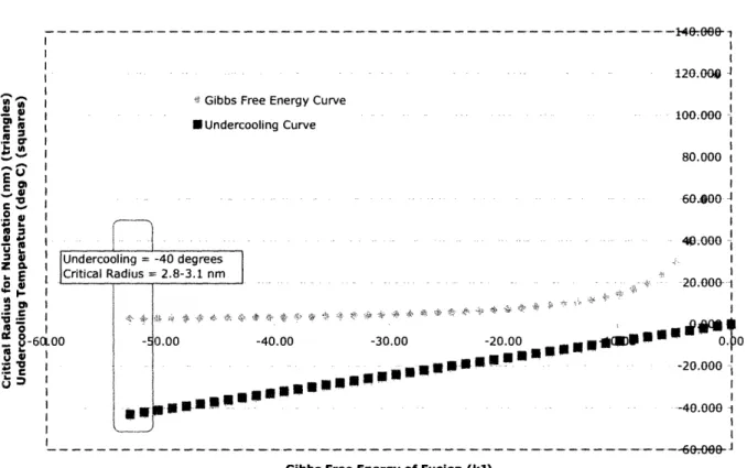
In order to understand the wide variations of pore size available within this process, Figure 10 is provided to show the dependence of the critical radius on the heterogeneous Gibbs fiee energy.
Dependence of Critical Radius on Gibbs Free Energy
120.0
U: Gibbs Free Energy Curve
'a-~ ~ ... ~~~~~~~~~~~~~~ 100.000 ~Cl I EUndercooling Curve ,g Or I _- | 80.000 t E , ... 60.8O0 J a X 4.000-...-.-..
Z cLi Undercooling = -40 degrees I
.E Critical Radius - 2.8-3.1 nm.0.
er §..- i_-- -- ···". :~v D ", -I~ -· -- 20.000- ---
' -6a.oo - 00oo -40.00 -30.00 -20.00 4OR D Q 0
- XIr tI -20.000
1
- I :-
-40.000-Gibbs Free Energy of Fusion (iJ)
0
Figure 10 Gibbs free energy of heterogeneous nucleation. Triangle data points indicate the critical radius of nucleation as it depends on AG. In order to solve for a known process an undercooling curve (squares) is
provided to gauge the correct critical radius.
It is important to notice that the critical radius increases with decreased undercooling. This makes sense, as it is easier to nucleate ice crystals far below the natural freezing temperature. Also, as the Gibbs free energy becomes more and more negative the radius continues to decrease. This would indicate that the reaction is favoring the formation of ice crystals and requires much less energy to complete the transformation.
By examining the chart and overlapping the critical radius with our desired undercooling temperature of -40°C we can see that our critical radius is between 2.8 and 3.1 nm. For calculation purposes we will assume that the average radius is 3.0nm. It would be interesting to
figure out how many molecules of H20 are contained within a particle of roughly 3.0nm.
cutar aalus
).9584A
Figure 11 Water molecule and its associated molecular radius.
The volume of a sphere is given in equation 1.8.
Vsphere = -lr3 (1.8)
3
Solving by setting r = 3.0nm we are able to find the volume of the nucleated particle to be V\pher= 1.13E-25 m 3. The molecular radius of a water molecule is roughly 0.9584 A. The volume a single water molecule is VH2o=3.687E-30 m3.Dividing the volume of the sphere by the
volume of the individual water molecule will give us a rough estimate of how many molecules have to spontaneously gather to form a particle of critical size.
Vsphere 1.13E - 25
VHeO - 25 =30, 699molecules (1.9)
VH20 3.687E - 30
So, approximately 30,000 water molecules must come together to form a particle of critical size. The next step in quantifying the lyophilization process is determining the nucleation rate and
growth rate of the particles once they have reached critical size.
3.3.1.2 Nucleation & Growth Rate
The nucleation rate describes the number of molecules forming per meter cubed per second onto the nucleation surface. This number is important because it can determine the induction time needed to reach the critical radius size for continued development controlled by the grow rate. Equation 1.10 shows the general form of the nucleation rate.25
C* = Cexp[ -] (1.10)