Publisher’s version / Version de l'éditeur:
Vous avez des questions? Nous pouvons vous aider. Pour communiquer directement avec un auteur, consultez la première page de la revue dans laquelle son article a été publié afin de trouver ses coordonnées. Si vous n’arrivez pas à les repérer, communiquez avec nous à [email protected].
Questions? Contact the NRC Publications Archive team at
[email protected]. If you wish to email the authors directly, please see the first page of the publication for their contact information.
https://publications-cnrc.canada.ca/fra/droits
L’accès à ce site Web et l’utilisation de son contenu sont assujettis aux conditions présentées dans le site LISEZ CES CONDITIONS ATTENTIVEMENT AVANT D’UTILISER CE SITE WEB.
7th International Conference on Structures of Fire [Proceedings], pp. 1-8,
2012-06-06
READ THESE TERMS AND CONDITIONS CAREFULLY BEFORE USING THIS WEBSITE. https://nrc-publications.canada.ca/eng/copyright
NRC Publications Archive Record / Notice des Archives des publications du CNRC :
https://nrc-publications.canada.ca/eng/view/object/?id=686e0f1a-74e5-4588-896d-1be7ed30094c
https://publications-cnrc.canada.ca/fra/voir/objet/?id=686e0f1a-74e5-4588-896d-1be7ed30094c
NRC Publications Archive
Archives des publications du CNRC
This publication could be one of several versions: author’s original, accepted manuscript or the publisher’s version. / La version de cette publication peut être l’une des suivantes : la version prépublication de l’auteur, la version acceptée du manuscrit ou la version de l’éditeur.
Access and use of this website and the material on it are subject to the Terms and Conditions set forth at
Hybrid fire testing of building structures
Hybrid fire testing of building
structures
Mostafaei, H.
NRC-54593
A version of this document is published in
7th International Conference on Structures of Fire, Zurich, Switzerland,
June 6-8, 2012, pp. 1-8
The material in this document is covered by the provisions of the Copyright Act, by Canadian laws, policies, regulations and international agreements. Such provisions serve to identify the information source and, in specific instances, to prohibit reproduction of materials without written permission. For more information visit http://laws.justice.gc.ca/en/showtdm/cs/C-42
Les renseignements dans ce document sont protégés par la Loi sur le droit d’auteur, par les lois, les politiques et les règlements du Canada et des accords internationaux. Ces dispositions permettent d’identifier la source de l’information et, dans certains cas, d’interdire la copie de documents sans permission écrite. Pour obtenir de plus amples renseignements : http://lois.justice.gc.ca/fr/showtdm/cs/C-42
7th International Conference on Structures in Fire
M. Fontana, A. Frangi, M. Knobloch (Eds.) Zurich, Switzerland, June 6-8, 2012
HYBRID FIRE TESTING OF BUILDING STRUCTURES
Hossein Mostafaei
Research Officer, National Research Council Canada, Ottawa, Canada e-mail: [email protected]
Keywords: Hybrid Test, performance-based assessment, fire resistance, numerical analysis, fire test building in fire.
Abstract. A performance-based fire resistance evaluation method, called hybrid fire testing (HFT), was developed and carried out at the Fire Research Program of the National Research Council of Canada (NRC). HFT offers a more cost-effective approach to the assessment of the full structures performance in fire than that of a full-scale test and provides more reliable results than prescriptive single component testing. In the HFT method, the whole building is divided into two substructures; 1) the test specimen and 2) the model component. Then, fire performance of the whole structure is evaluated based on coupling the performance of the two substructures and by including their interactions in real time during the simulation. In this study, the HFT was applied for a 6-storey reinforced concrete building structure with a fire compartment scenario on the first floor. The test specimen was a worst-case scenario column in the compartment of fire origin in the building. The specimen was physically tested in a full-scale furnace, and the remaining of the building structure was modelled using numerical analysis software. In the HFT, the real time interactions between the two substructures are based not only on including the experimental results obtained from the test specimen into the numerical model component but most importantly also including feeding the output of the model component back into the test specimen environment (e.g. vertical and lateral loading changes). In other words, both equilibrium and compatibility conditions are satisfied between the test specimen and the model component. The results of this study show that the HFT is achievable and can be performed successfully for fire performance evaluation of a building structure.
1 INTRODUCTION
Traditional fire resistance testing evaluates the performance of individual building elements with no consideration given to the interaction with other parts of the building. On rare occasions, fire performance is assessed by constructing and testing an entire building, a very expensive approach. In the last few years an attempt was made at the Fire Research Program of the National Research Council of Canada (NRC) to explore solutions for such a gap by developing a performance-based approach called Hybrid Fire Testing (HFT).
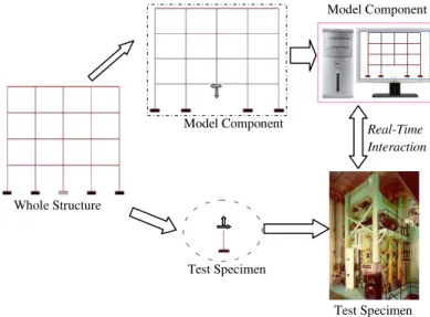
HFT is based on performance simulation of the whole building using a sub-structuring approach. That is to split the whole structure into two substructures: 1) test specimen and 2) model component, as shown in figure 1. The test specimen is the structural element or assembly that is exposed directly to fire. The model component includes the remaining of the building structure, excluding the test specimen. The model component could include both elements exposed to fire and elements at ambient temperature, providing the analysis software has the capability of performing structural analysis at elevated temperatures.
Hossein Mostafaei
Usually, in a building fire scenario, fire is expected to be confined in the fire compartment at the fire’s origin. Therefore, compared to the total number of structural elements in a building, only a few of them are likely to be exposed to fire. Since more reliable models are available for structural analysis at ambient temperature than that at elevated temperatures; the test specimen should include all the elements exposed to fire, or at least the worst case scenario element/assembly, in the fire compartment. In this study, the column in the middle of the fire compartment, on the ground floor of the building, is selected as the test specimen, which is the only column exposed to fire. There are also four beams in the fire compartment, but they are simulated as part of the model component using SAFIR software [1]. SAFIR software has the capability of simulating structures at both ambient and elevated temperatures and therefore, it was selected for analysis of the model component of the HFT.
Figure 1. Division of a structure into test specimen and model component in the HFT.
One of the most important parts of the HFT process is the real-time interactions between the test specimen and the model component. That means, during the application of HFT, interface loads and deformations, between the test specimen and the model component, should be updated, at each interval time during the hybrid fire testing, to satisfy both compatibility and equilibrium conditions. The interactions could be performed using a controlled load or a deformation controlled method. For this study, the interface deformations on the model component were controlled by displacement of the test specimen and load on the column was controlled by the load obtained from the analysis of the model component. The detail of the HST methodology is provided by Mostafaei [2]. This paper provides only the results of the HFT application for the 6-storey building.
In the HFT described in this study, both the test specimen and the model component are exposed to an appropriate design fire. In other words, the temperature curve should be known before the test. In case of a real fire test, interactions must include temperature components in addition to the load and deformation. That is to measure temperatures for the test specimen and impose the model component to the same temperatures in the analysis.
Test Specimen Test Specimen
Model Component Real-Time
Interaction
Whole Structure
Hossein Mostafaei
The cost for application of HFT is very low, almost the same as that of the traditional prescriptive tests, however resulting in more reliable results than the prescriptive testing. Furthermore, the method is very flexible. Various building structural configurations and properties could be tested by building only the structural elements that are exposed to fire.
HFT can also be implemented remotely using different physical testing facilities and a simulation analysis from different locations anywhere in the world. This could be implemented by applying a proper communication technique between the software and physical testing facilities.
2 HFT METHODOLOGY
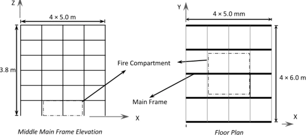
The HFT method conceptually was developed based on a sub-structuring analysis concept. In such an analysis, the whole structure is divided into two or more sub-structures by including force and deformation interactions amongst the sub-structures. The main purpose of sub-structuring analysis is to reduce the amount of analytical calculations by distributing them among different computers/processors. For instance, one of the main rules in structural decomposition is to have minimum interface nodes and have equal numbers of degree of freedom in the sub-structures. This would result in reduction of time and memory required for the analysis, since multiple processors will be used instead of one for the analysis [3]. However, for the HFT, the sub-structuring method is to divide the structure into two sub-structures, one being tested physically, the test specimen, and one being simulated numerically, the model component. Size of the test specimen substructure depends on the capacity of the test facility. For instance, in case of this study, the column furnace at the NRC could expose a full-scale column specimen. Therefore, the test specimen substructure consists of the worst case scenario column in the fire compartment. If a larger facility is accessible where the entire fire compartment can be simulated then the test specimen substructure includes all the elements of the fire compartment and the model component substructure includes the remaining of the structure, the elements at ambient temperature. Figure 2 shows the 6-storey building structure, for this study, with a fire compartment on the first floor. As shown in the figure, a column on the first floor is the column in the assumed fire compartment, which has been selected as the test specimen and the remaining of the 6-storey building is considered as the model component. In this study, symmetric conditions were assumed for the applied load and fire load. That means fire compartment was located symmetrically in the middle of the building on the first floor and the building was loaded uniformly under the typical dead load and live load, uniformly. This was done to simplify the first time implementation of the HFT. For application of HFT, in the case where the test specimen is located on upper floors or at a corner span, information is provided by Mostafaei [2].
Considering the above symmetric conditions, moments about the horizontal axes for beams next to the test specimen, the centre column on the first floor, will be the same but in the opposite directions. Therefore, no rotation is expected at the top end of the test specimen. Furthermore, fire compartment is assumed to be in the centre of the first floor. In this case, a symmetric distribution for thermal expansion of the floor is expected, resulting in zero lateral deformation in the centre of the floor where the test specimen is located, and a maximum lateral deformation at the edge of the floor. Therefore, the test specimen is not subjected to any lateral deformation at the floor level during the fire. In other words, the only interaction components between the test specimen and the model component are the vertical load, column’s axial load, and the vertical deformation at the top end of the test specimen. Figure 3 shows the location of fire compartment in the building as well as the elevation and floor plan of the building.
Based on the above simplification, the HFT can be implemented, in the following simple steps: Step 1: Run a structural analysis under the applied load for the whole structure, at ambient temperature and obtain the vertical load and vertical deformation at the top end of the test specimen, top of the first floor’s centre column.
Hossein Mostafaei
Figure 2. Division of a 3D 6-storey structure into Test Specimen and Model component in the HFT.
Figure 3. Elevation and floor plan of the building with location of the fire compartment.
Step 2: Run another structural analysis under the same applied loads but for the model component only, while the frame is subjected to the vertical deformation obtained in Step 1 for the top end of the test specimen. This will create a vertical constraint at the top end of the test specimen resulting in a vertical load reaction. Obtain the vertical load reaction. If the load reaction is different from the axial load obtained in Step 1, then an adjustment in deformation may be needed to minimize such a difference, as described in Mostafaei (2011). Normally the difference is very small and this can be ignored. The obtained axial load and vertical deformation in this step are considered as the initial values. The initial vertical load and initial vertical deformation for the top end of the test specimen of this study were 2000 kN and -0.00133 m respectively. Test Specimen Real-Time Interaction Whole structure Model Component 6 × 3.8 m 4 × 5.0 mm 4 × 6.0 m Main Frame
Middle Main Frame Elevation Floor Plan
X X Z Y 4 × 5.0 m Fire Compartment
Hossein Mostafaei
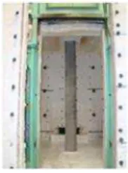
Step 3: Apply the initial vertical load, obtained from Steps 1 and 2, on the top of the test specimen, as the axial load of the column, gradually. Once the load is stabilized, the test is ready to start. Figure 4 shows the column specimen at this stage before the test.
Figure 4. Test specimen installed in the column furnace testing facility, just before the start of the fire.
Step 4: Start the fire in the furnace for the test specimen.
From here, all the steps will be repeated for each time increment, Δt.
Step 5: Read new vertical deformation of the test specimen, at the top end. Then run the analysis for the model component, while it is subjected to the previous applied load and to the new vertical deformation of the test specimen and obtain the new vertical load reaction.
Figure 5 shows the computer used for numerical simulation of the model component as well as the new digital controlling system of the column, used for the HFT.
Figure 5. The column furnace controlling system and the computer simulator used for application of the HFT. Step 6: Adjust the vertical load of the test specimen, axial load of the column specimen in the furnace, with the new vertical load reaction obtained from the analysis in Step 5.
Step 7: Repeat steps 5 and 6 for each time increment, Δt, for the entire test including the cooling phase. Δt depends on the level of the acceptable error, e.g. acceptable variations of the vertical load and deformation between the test specimen and the model component. For this study, time increment was approximately every 5 minutes.
3 THE 6-STOREY BUILDING SPECIMEN
A 6-storey reinforced concrete building was designed as the whole structure specimen for this study. The design was based on the North American codes and standards. Details for the design of the 6-storey structure and information on the test specimen can be found in the original report [2]. Figure 6 shows the overall 3D structural frame configuration of the building.
New Column Furnace Digital Controlling System 3D Computer Simulation of the model component
Hossein Mostafaei
Figure 6. The 3D frame of the 6-storey reinforced concrete building designed for this study.
4 IMPLEMENTATION OF THE HFT
For implementation of HFT the NRC column furnace testing facility was used to perform fire test of the test specimen. The numerical analysis of the model component was simulated using a structural analysis software called SAFIR [1]. SAFIR has the capability of simulating the structures in fire; therefore, beams located in the fire compartment were simulated considering their fire exposure. The interactions between the test specimen and the model component was implemented manually during the test, by reading the test results and including them in the input file of SAFIR and after analysis, by reading the output file of SAFIR and posing the new vertical load on the test specimen. An interface software was developed to speed up the interaction process, which was being performed approximately every 5 minutes.
Mechanical properties of the concrete and steel reinforcement for all the cross sections were assumed identical to that of the column specimens. Beams and columns were simulated using fibre models and therefore shear responses of the elements were considered negligible. All the connections were considered moment resisting connections.
At the start of the test the measured ambient temperature was 23.4oC. The average temperatures in the fire compartment, both in the furnace and in the simulation, during the HFT, were controlled based on the CAN/ULC-S101 standard temperature-time curve [4].
5 HFT RESULTS
The HFT results include temperature distributions on the test specimen, driven from the furnace test, and all the elements, exposed to fire, in the model component, driven from the numerical analysis. Vertical load and deformation, as well as, deformation and the internal loads of the model component are determined and recorded at each time increment during the HFT. Therefore, comprehensive performance response information can be provided by the HFT for the whole structure.
As an example for the test specimen, Figure 7 illustrates temperatures in cover concrete and temperatures at the centre of the concrete cross section, compared with the average temperatures in the furnace, during the fire and the cooling phase.
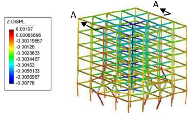
As an example for the model component, Figure 8 illustrates deformation of the building at the time when the fire exposure stopped, at 4 hours. Figure 9 shows only half of the building in Figure 7, the rest of the building was hidden to better observe the structural response at the fire compartment location.
Hossein Mostafaei
Figure 7. Temperatures in the furnace, cover concrete and centre of the concrete cross-section of the test specimen.
Figure 8. Vertical displacement response of the model component of the 6-storey building, after 4 hours fire exposure.
Figure 9. Section A-A of building in Figure 8.
The results of the numerical analysis include shear and axial load, moment, deformations and rotations for all the building elements and nodes as well as temperature distributions of the beams in the fire compartment. The main purpose of this study is to demonstrate that the HFT is achievable. Although, all the performance components for the building structure were calculated during the test, this study focuses more on the application of the HFT. Therefore, only the overall results of structural performance of the building were provided in this paper.
A
A
Hossein Mostafaei
6 VERIFICATION OF EQUILIBRIUM AND COMPATIBILITY CONDITIONS
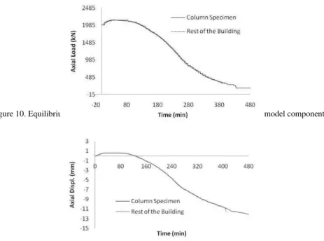
For the HFT, equilibrium and compatibility conditions between the test specimen and the model component need to be satisfied. This is required to ensure that the interactions between the two substructures are adequately performed during the HFT and that the results of the two substructures could represent the results for the whole structure. The two main interaction components, in the case of the 6-strorey building and the fire scenario in this study, are the vertical load and the vertical displacement at the interface of the two substructures. Therefore, the equilibrium condition will be evaluated by comparing vertical load of the test specimen and the model component. The compatibility condition will be assessed by comparing vertical displacement of the test specimen and the model component at their interface point. Figure 10 shows verification of the equilibrium condition and Figure 11 shows verification the compatibility condition. The results indicate that both equilibrium and compatibility conditions were satisfied during the HFT.
Figure 10. Equilibrium: vertical load at the interface of the test specimen and the model component.
Figure 11. Compatibility: vertical displacement at the interface of the test specimen and the model component.
7 CONCLUSION
A new hybrid fire test (HFT) was implemented for the performance evaluation of a 6-storey building structure exposed to fire. Using the HFT, the whole structure was divided into two substructures: a) test specimen and b) model component. The test specimen was tested physically using the NRC column furnace facility and the model component was simulated using numerical analysis software. Interaction components between the test specimen and the model component included load and deformations at the interface point. Both equilibrium and compatibility conditions were satisfied during the HFT performed for the 6-storey building. This study showed that application of a hybrid fire test for a typical structure, e.g. building, is achievable.
Hossein Mostafaei
REFERENCES
[1] SAFIR, Franssen J.-M., “A. Thermal/Structural Program Modelling Structures under Fire”, Engineering Journal, A.I.S.C., Vol 42, No. 3, 143-158, 2005.
[2] Mostafaei, H. “Hybrid Fire Testing for Performance Evaluation of Structures in Fire - Part 1 Methodology,” Research Report No. RR-316, National Research Council Canada, pp.20, 2011. [3] Kaveh, A., Bahreininejad, A., Mostafaei, H. "Hybrid graph-neural method for domain
decomposition," International Journal Computers & Structures, 70, pp. 667-674, 1999.
[4] CAN/ULC-S101, “Fire Endurance Tests of Building Construction and Materials”, Underwriters’ Laboratories of Canada, Scarborough, ON