An Analysis of Physical Object Information Flow
within Auto-ID Infrastructure
by
Tatsuya Inaba
BACHELOR OF ENGINEERING IN ELECTRICAL ENGINEERING UNIVERSITY OF TOKYO, 1991
Submitted to the Center Engineering Systems Division in Partial Fulfillment of the Requirements for the Degree of
MASTER OF ENGINEERING IN LOGOSTICS at the MASSACHUSETTS INSTITUTE OF TECHNOLOGY
JUNE 2004
© Tatsuya Inaba. All rights reserved.
The author hereby grants to MIT permission to reproduce and to distribute publicly paper and electronic copies of this thesis document in whole or in part.
Signature of Author ...
Certified by ...
...
Engineering Systems Division May 7, 2004
--. / George A. Kocur Senior Lecturer of Department of 9'<`?w'dnvironment Engineering Thesis Supervisor Certified by ... ... ...
James B. Rice Director, ISCM Program of Center tokYransportation and jogistics Ah3is $,ervisor V j ... MASSACHUSETTS INSTITUTE OF TECHNOLOGY
JUL 2 7 2004
LIBRARIES
,... ... ... . (/Yosef SheffiProfessor, Engineering •ystems Division Professor, Civil and Environmental Engineering Department Director, MIT Center for Transportation and Logistics
ARCHIVES
A ccented hv
An Analysis of Physical Object Information Flow
within Auto-ID Infrastructure
by
Tatsuya Inaba
Submitted to the Engineering Systems Division on May 7, 2004 in Partial Fulfillment of the Requirements for the Degree of
MASTER OF ENGINEERING IN LOGISTICS
ABSTRACT
The application of Radio Frequency Identification (RFID) has been studied for decades, and many field trials have been executed to evaluate the usability of RFID systems, the business case of RFID applications and so forth. One of the trial fields is its application to supply chain management (SCM) because the RFID technologies are thought to improve visibility of physical objects dramatically. Through this trial phase, benefits and feasibility of RFID have been confirmed, and as a result, major retailers, such as Wal-Mart, Target, and Metro, have decided to implement RFID. At the same time, these trials reveal the necessity of RFID standards. Among these newly developed RFID standards, Auto-ID standard, which was originally developed by Auto-ID Center, is a strong candidate to be a de-facto standard.
Auto-ID technologies consist of data standards and software architecture components. Data standards also consist of two components: Electronic Product Code (EPC) and Physical Markup Language (PML). On the other hand, software architecture components consist of four components: readers, Savant, EPC Information Server (EPC-IS), and Object Name Service (ONS). EPC-IS. which defines the interface of the servers that store physical object information, plays a key role in realizing business processes that the RFID technologies are expected to realize. In this thesis, we propose architecture of EPC-IS by defining the requirements for EPC-IS through generic business processes executed in Auto-ID infrastructure. The architecture we propose is not a monolithic message schema but three simple message schemas with vocabulary sets that are separately defined in dictionaries. By taking this structure, we achieve robust and scalable interface. We also evaluate our proposal by applying it to the problems
found in the RFID trials and possible future business processes.
Thesis Supervisor: George A. Kocur
Acknowledgement
First and foremost, I would like to thank to my family to understand my will and support my study at MIT. Without their understanding and support I had not had the chance to study and mingle with my friends at MIT.
I also thank to my friends who cheer me up and give me valuable advices. With their support, I can keep high motivation to learn new things and write a thesis.
Regarding the thesis, I am very grateful for the support, advices and encouragement from my advisors George Kocur and Jim Rice. Their advices helped me to focus the thesis topic, construct the logic, and break the wall when I was stuck.
I also would like to appreciate all at Auto-ID Lab, especially Robin Koh. The discussion with him was very informative and helped me to develop the scope of my thesis. He sometimes pushed me to move forward and gave me advices and encouragement. He also gave me many contacts that are essential to my thesis. The visit to the Auto-ID Lab was one of the most valuable experiences I had through this thesis writing.
I would like to thank to the architects at EPCglobal, especially Ted Osinski. The advices from him helped me to develop the proposal I made in this thesis.
Last but not least, I would like to show my appreciation to all the staff and friends at MLOG Program. The experience we had, to discuss, to chat, to help each other and to eat and drink, made the life at MIT more valuable, fruitful, and enjoyable.
Table of Content
1. Introduction... 7 2. Background... 10 2.1. Auto-ID Standard ... 10 2.1.1. Abstract ... ... 1010... 2.1.2. Readers... 10 2.1.3. Savant ... 11 2.1.4. EPC-IS ... 11 2.1.5. )N S ... 12 2.1.6. EPC ... 12 2.1.7. :'ML ... 12 2.2. Research of EPC-IS ... 13 2.2.1. H istory of EPC-IS ... ... ... ... 132.2.2. Research review on EPC-IS ... ... 13
2.2.3. Approach of this thesis ... ... ... 14
2.3. B2B standards ... 14
2.3.1. Introduction ... 14
2.3.2. ebXM L ... 14
2.3.3. R osettaN et ... 15
2.3.4. Sum m ary of B2B standard observation... 15
3. Objective., Assum ptions and M ethodology ... 16
3.1. Objective ... ... ... ... ... 16
3.2. A ssum ptions ... ... 16
3.2.1. Physical object type ... 16
3.2.2. Supply chain range... 17
3.2.3. Server w ith EPC-IS existence ... 17
3.2.4. B2B connection ... 18
3.3. M ethodology ... 18
4. Requirement Analysis ... 19
4.1. Business process selection ... 19
4.2. Query product-level data business process. . . ... 20
4.2.1. Cverview ... 20
4.3. Query instance-level data business process ... 23
4.3.1. Overview ... 23
4.3.2. Business process flow ... ... 23
4.4. Q uery location data business process ... 26
4.4.1. O)verview ... 26
4.4.2. Business process flow ... 26
4.5. Q uery path data business process ... ... ... ... 29
4.5.1. Overview ... 29
4.5.2. Business process flow ... 29
4.6. Exceptions ... 32
4.6.1. C)verview ... 32
4.6.2. Business process flow for notify exception ... 32
4.6.3. Business process flow for query exception ... 32
4.7. Requirem ent definition ... 36
4.7.1. M essage types ... 36
4.7.2. Scalability of the m essage ... 36
4.7.3. :)ata type . ... ... 36
4.7.4. Mechanism to translate historical data into business process ... 37
5. M odeling ... 38
5.1. M odeling direction ... 38
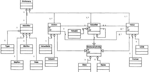
5.1.1. Separation of message structure from dictionary structure ... 38
5.1.2. M eaning of adopting D ictionary ... ... 38
5.1.3. Dictionary structure ... ... 38 5.2. D ictionary ... 3... 39 5.3. M essage ... 41 5.3.1. N otify m essage ... 42 5.3.2. Q uery/Response m essage ... ... .... 44 5.3.3. Acknowledge m essage ... ... 48 6. Evaluation ... 50
6.1. Im perfect tag detection ... 50
6.2. Security ... 52
6.3. Further business processes ... ... 53
6.4. Handling trace business process ... 53
6.4.1. Business process flow ... 54
6.4.2. Requirem ent analysis ... 57
6.5. Assem bly trace business process ... 57
6.5.1. Business process flow ... 58
6.5.2. Requirem ent analysis ... 62
6.6. Order track business process ... 62
6.6.1. Business process flow ... 63
6.6.2. Requirem ent analysis ... 66
7. Summary and Suggestions ... 67
7.1. Sum m ary ... 67
7.1.1. EPC Inform ation Service architecture ... 67
7.1.2. M essage...67
7.1.3. Dictionary ... 68
7.2. Suggestions for future study ... 68
7.2.1. Standard developm ent ... 68
7.2.2. Impact assessment of merging EDI/B2B infrastructure with Auto-ID infrastructure ... 68 8. References ... 70 9. Appendix ... 73 9.1. Dictionary ... 73 9.1.1. D ictionary Schem a ... 73 9.1.2. Event D ictionary ... 74 9.1.3. Property Dictionary ... 76 9.2. M essage ... 79 9.2.1. Schem a ... 79
1. Introduction
The history of Radio Frequency Identification (RFID) is long, and studies and implementations of RFID go back to the mid-20th century [1]. Although the technology is categorized as RFID, the technology behind RFID applications at that time was different from that of today. Currently RFID technology premises the use of IC tag, which stores information about the object to which the IC tag is attached. This IC tag based RFID technology has been studied for decades, and based on these studies field trials have been executed to evaluate wide range of applications.
One of the trial fields of RFID has been its application to supply chain management (SCM) because this technology is thought to dramatically improve the visibility of physical objects and this increased visibility will bring companies in the supply chain many benefits, such as the reduction of inventory, reduction of inventory management costs, and realization of value added service.
Objectives of these trials are both technical and business verifications, which range from the feasibility of RFID infrastructure, such as the usability of IC tag and radio frequency signal reader, the accuracy of identification [2], and the estimation of RFID impact on the real business [3].
Through trial phase, benefits and feasibility of RFID infrastructure has been confirmed, and as a result, major retailers, such as Wal-Mart, Target, and Metro, have decide to deploy RFID implementation. At the same time these trials reveal the necessity of RFID standards. RFID standards are beneficial in many reasons. Major benefits are: 1) guarantee of interoperability, 2) acceleration of implementation, 3) reduction in cost of RFID components.
The RFID system is more beneficial when it is used among companies. To guarantee interoperability, standards are necessary. Without standards, IC tags of a manufacturer may not be detected by readers made by other manufacturers. This problem is not limited to the relation between IC tags and readers but occurs between other components as well, such as information handling between readers and systems, data stored in IC tags, and information exchange within the RFID system.
In order to deploy standards, standard organizations not only define standard specifications but also provide know-how by publishing implementation guidelines and organizing conferences to share success stories about implementation. With these efforts, companies can accelerate RFID system implementation with fewer troubles.
Reduction in cost of RFID components is a secondary benefit from RFID standard deployment. If a standard is defined and deployed to many companies, economy of scale works and, as a result, manufacturers of each component can achieve lower cost, and that benefits companies that implement RFID systems.
Among the RFID standards, the Auto-ID standard, which was originally developed by Auto-ID Center and is managed by EPCglobal, is a strong candidate to be a de-facto standard. Auto-ID Center was a federation of research universities that was originally founded in 1999 and is now
Auto-ID Lab. In Auto-ID Lab there are six universities: Massachusetts Institute of Technology (MIT), University of Cambridge, University of Adelaide, Keio University, Fudan University, and University of St. Gallen [4]. EPCglobal is a non-profit organization, and its goal is to realize global, multi-industry adoption and implementation of the EPCglobal Network [5].
The EPCglobal Network is by definition a set of technologies that enable immediate, automatic identification and sharing of information on items in the supply chain [6]. EPCglobal Network consists of software architecture components and data standards. Software architecture components also consist of four components: readers, Savant, EPC Information Server (EPC-IS), and Object Name Service (ONS). On the other hand, data standards consist of two components: Electronic Product Code (EPC) and Physical Markup Language (PML). In this thesis, we use the EPCglobal Network and Auto-ID technologies to mean the same thing.
Readers are devices for detecting tags when tags enter the read range. EPCglobal has published the Auto-ID Reader Protocol Specification. This specification defines interactions between readers and other Auto-ID compliant software components, such as Savant [7].
Savant is middleware software designed to control information flow between readers and EPC-IS. EPCglobal has published the Savant Specification. This specification defines the functions and interface of Savant. Data detected by readers is filtered, aggregated, counted and reduced by Savant. Savant also controls information flow between readers and the enterprise applications [8].
EPC-IS is an interface standard to define how to update and retrieve data of physical objects stored in servers. Types of data stored in the servers are product-level property data such as the size of physical objects, instance-level property data such as shelf life, and historical data such as the detected record of physical objects. EPCglobal has not published specifications for EPC-IS [9].
ONS provides global look-up service to the Auto-ID compliant software components. The function is similar to Domain Name Service (DNS) in the Internet. EPCglobal has published the Object Name Service Specification [10].
EPC is the identification schema for physical objects. EPCglobal has published EPC Tag Data Specification. In the specification, in addition to EPC, Filter Value and encoding and decoding rules are specified [ 11].
PML is an eXtensible Markup Language (XML) vocabulary set, which is used to describe all the information exchanged in the Auto-ID infrastructure. PML consists of two parts: PML Core and PML Extension. PML Core is specified in the Physical Markup Language Specification Core [12].
These are the components defined by EPCglobal. In order to fulfill the benefits of Auto-ID technologies, information about physical objects needs to be exchanged effectively within the Auto-ID infrastructure, and a key component to realize this information exchange is EPC-IS as an interface for servers that store physical object information. However, currently the specification of EPC-IS has not been published yet.
focus on real-time applications. If companies implement an application that needs historical data of physical objects, knowing how to use EPC-IS is necessary. The other reason is that Auto-ID implementation is still on a trial basis and the priority of interoperability within the Auto-ID infrastructure is still not so high. If companies need to exchange more information about physical objects, the necessity of a standard method of using EPC-IS becomes more crucial.
As we describe above, there is a gap between fundamental expectations towards the Auto-ID infrastructure and the current publication of standards. In this thesis, we would like to fill the gap by proposing a solution: architecture that can exchange information with EPC-IS.
This thesis is laid out as follows: Chapter 2 reviews the background of this thesis, such as Auto-ID standards. Chapter 3 explains objectives of the thesis and discusses assumptions used in the thesis. We also introduce the methodology employed in the thesis. Chapter 4 defines the requirements for the model we propose, and the following chapter models solutions. Chapter 6 evaluates the model with problems that are currently revealed and possible future scenarios and makes it more robust. Chapter 7 concludes our proposal and discusses further research questions that need to be addressed.
2.
Background
Since we will propose architecture of EPC-IS in this thesis, components, functions and situation of the Auto-ID standard is necessary as background information. In addition to that, we review research that has been done about EPC-IS. At the same time, we introduce Business to Business (B2B) standards as a relevant technology in this chapter.
2.1.
Auto-ID Standard
2.1.1. Abstract
The Auto-ID standard is a set of RFID standards which were originally researched and published by Auto-ID Center and are maintained by EPCglobal now. Auto-ID Center, which changed its name to Auto-ID Lab in November 2003, is a federation of six universities worldwide: MIT, University of Cambridge, University of Adelaide, Keio University, Fudan University, and University of St. Gallen. On the other hand, EPCglobal is a non-profit organization entrusted to drive global, multi-industry adoption and implementation of the EPCglobal Network and is a joint venture of Universal Code Council (UCC) and EAN International, which are also non-profit organizations to manage barcode, Electronic Data Interchange (EDI) standards, and B2B integration standards [13].
The EPCglobal Network is a set of technologies that enable immediate, automatic identification and sharing of information on items in the supply chain. EPCglobal Network, which is equivalent to Auto-ID technologies, consists of software architecture components and data standards. The software architecture components consist of four components: readers, Savant, EPC-IS, and ONS, and the data standards consist of two components: EPC and PML.
2.1.2. Readers
Readers are the devices which read and write the data stored in the Auto-ID compliant IC tags. Functions and interface of the readers are defined in two Auto-ID standards: Reader Protocol, which defines the upstream wire part of the readers and Radio Frequency Communication Protocol, which defines the downstream wireless part of the readers.
Reader Protocol defines three layers: Reader Layer, Message Layer, and Transportation Layer. Reader Layer is the layer that defines the content and format of the message exchanged between readers and Savant. Reader Layer defines commands sent from Savant and functions that readers should perform when commands are sent to readers, such as IC tag read trigger, filter, and send messages to IC tags.
Message Layer is the layer that defines how command messages defined in Reader Layer are formatted, transformed, and carried on a specific network transport, and Transportation Layer is the layer that defines transport facilities provided by the operating system or equivalent.
In the Reader Protocol specification, Message Layer and Transportation Layer are defined as Message Transportation Binding (MTB). Reader Protocol defines commands sent from Savant and MTB.
Regarding Radio Frequency Communication Protocol, there are three communication protocols deeined in Auto-ID standards: 900 MHz Class 0 Radio Frequency (RF) Identification Tag Specification, 13.56 MHz ISM Band Class I Radio Frequency Identification Tag Interface Specification, and 860MHz - 930 MHz Class 1 Radio Frequency (RF) Identification Tag Radio Frequency & Logical Communication Interface Specification [14] [15] [16].
Each of the communication protocol specification defines radio signal frequency, radio signal power, shape of radio signal, message frame, command to IC tags, power of radio and so forth. It also refers to the functions of the IC tag as a corresponding device to communicate with.
2.1.3. Savant
Savant is a software system that is located between the enterprise application system and readers. The primary function of Savant is to reduce the vast amount of data read by readers; therefore, by this nature, Savant has functions to communicate with the enterprise applications and readers and to sort out data detected by readers. In addition, Savant has functions to communicate with ONS and EPC-IS as well. The specification of Savant is defined in Savant Specification.
Savant Specification comprises two parts: specification of Processing Modules, which defines functions which reside in Savant, and interface with other Auto-ID components. In Savant Specification version 1.0, only interface for the enterprise applications is defined.
Processing Modules define functions of Savant. Processing Modules are not only defined by EPCglobal but also by users. The combination of Processing Modules is arbitrary, and users can choose whatever they need to fulfill their business goals except for the Standard Processing Module. The Standard Processing Module, which defines minimal functions of Savant, is mandatory.
The interface specification in Savant Specification defines message structure, MTB, and the transportation protocol that Savant premises.
2.1.4. EPC-IS
EPC-IS is an interface that defines protocol to access to servers which store physical object data. The data is exchanged in PML format.
Servers for physical object information store two types of data: historical data and property data. Historical data is event records sent by Savant, and property data is a set of relevant
information about physical objects. Property data consists of the product-level property data and the instance-level property data. Examples of the product-level property data are the size and the manufacturer of the physical object, whereas examples of the instance-level property data are the expiration date and the purchase order document number for the physical object. Specification of EPC-IS has not been published, but a couple of studies have been done for EPC-IS. We introduce them in the following section along with the history of EPC-IS.
2.1.5. ONS
ONS is a global lookup service that connects EPC with one or more Uniform Resource Identifiers (URIs) where more information about the physical object is stored. The location may be servers with EPC-IS, web sites, and other Internet resources. The specification of ONS is defined in ONS Specification.
ONS Specification defines the flow of lookup, method to convert EPC to URI format, and message format of the lookup query. ONS uses the same method that Domain Name Service (DNS) uses. I DNS, URIs and IP addresses are linked, whereas URIs and EPC are linked in ONS.
2.1.6. EPC
EPC is the fundamental identifier for physical objects. The specification of EPC is defined in EPC Tag Data Specification. EPC Tag Data Specification defines the format of EPC, and the encode/decode scheme with other industry identifiers, such as Serialized Global Trade Identification Number (SGTIN) and Serial Shipping Container Code (SSCC). All the encode/decode schemes are specified with the header value.
The number of the digits defined for an identifier is 96 digits, but, in order to meet industry requirements to collect the tag data effectively, EPCglobal defines Standard EPC Tag Data, which consists of EPC and optional Filter Value.
2.1.7. PML
PML is an eXtensible Markup Language (XML) vocabulary set, which is used to describe all the information exchanged in the Auto-ID infrastructure. PML consists of two parts: PML Core and PML Extension.
PML Core is for the common vocabulary that is commonly used in different industries and that describes basic attributes in the Auto-ID infrastructure, whereas PML Extension is for the industry specific vocabulary set. PML Core is defined in PML Core Specification by EPCglobal, but PML Extension may not be defined by EPCglobal but by other industry initiatives.
PML Core Specification defines the range of the specification, XML Schema for PML Core. PML Core schema describes EPC, date time stamp of event, EPC of the reader, and the related data, such as types of read command.
2.2.
Research of EPC-IS
2.2.1. History of EPC-IS
The necessity of EPC-IS has been recognized since the initial stage of the Auto-ID technology development because one of the primary concepts of Auto-ID technologies is to store minimal data in the IC tag and to store other related data in the servers in the Auto-ID infrastructure. In order to realize this concept, PML has been developed as the common language to exchange information about physical objects, and a database to store the related information of physical objects has been proposed [17].
Initially this proposed database was called PML Server. However, as the study went on, researchers realized that related information might not be stored only in the PML Server and that it might be stored in the other enterprise systems, such as the enterprise resource planning (ERP) system. Based on this observation, researchers became focused on the interface of the database, and the interface is called EPC-IS. Until now, we have used the same term and studies have been done to better define the interface.
2.2.2. Research review on EPC-IS
Studies of EPC-IS have difficulty by nature because they are affected by industries to which EPC-IS is applied but to define the common use cases among different industries is not easy. The relatively lower necessity of EPC-IS standards also affects the research in this field. As written in Chapter 1, the publication of EPC-IS has been late because initial trials are focusing on applications which use real-time data, the data stored in the server can only be used with a proprietary method, and interoperability is not a high priority in the trials. Of course, the difficulty to define common use cases among industries is the main reason for the delay.
However, a couple of studies have been done by Cambridge University, one of the universities in the Auto-ID Lab. Approaches taken in the studies are to analyze characteristics of the data which is supposed to be stored in the servers in the Auto-ID infrastructure and also to define how to use the data [18].
The studies reveal that servers store two categories of data: the historical data and the property data. The property data is also divided into the product-level property data and the instance-level property data. This data type definition helps researchers to categorize use cases of each data type, and from this categorization they analyze efficient methods to retrieve data stored in the servers.
One fundamental assumption they make is that EPC-IS is different in different industries.
Based on this assumption, their focus is to provide technology components, such as query methods and database schemas for EPC related data, and to assess how proposed components are compatible with the existing industry standards.
2.2.3. Approach of this thesis
In this thesis, we take a different approach from the studies done by Cambridge University. We use the same data type category that they define: historical data and property data (product-level and instance-level). We also define use case as generic business processes, which are explained in Chapter 4. The difference is how to achieve compatibility with the existing industry standards. Our approach is to propose information flow architecture with compatibility in the component level, which is defined in a dictionary as explained in Chapter
5.
The benefit of this approach is that this information flow architecture can be used as a base model of new industry standards and that each industry can develop its standard by modifying it. The drawback of this approach is that it may be difficult to adopt the information flow architecture if the information flow architecture used in the industry is different from our model.
2.3.
B2B standards
2.3.1. Introduction
Although EPC-IS is not used only between different companies, it shares many characteristics with B2B standards. Common components of B2B standards are messaging protocol, vocabulary, message schema, choreography, and registry/repository scheme [19]. Not all the industry standards define all the components, but they provide most of them by referring other standards. In this section, we introduce two industry B2B standards that we refer for this thesis.
2.3.2. ebXML
ebXML (Electronic Business using eXtensible Markup Language) is a modular suite of specifications that enables enterprises of any size and in any geographical location to conduct business over the Internet. Using ebXML, companies have a standard method to exchange business messages, conduct trading relationships, communicate data in common terms and define and register business processes [20]. ebXML was started in 1999 as an initiative of OASIS and the United Nations/ECE agency CEFACT. It provides all the components listed in the introduction subsection. In addition to that, ebXML defines collaboration protocol agreements, which specify procedure to agree terms and condition on line.
One of the significant aspects of ebXML is the wide coverage of the components and industries. One of the drawbacks, on the other hand, is the speed of the standard defining process. This is inevitable for developing the comprehensive standard.
Another characteristic of the standard is to try to define each component separately and make it reusable. For example, business messages are not designed as a monolithic gigantic message but as a combination of a vocabulary set (ebXML calls it Core Component) and message schemas. The background technology to make ebXML define standard components separately is XML [21].
2.3.3. RosettaNet
RosettaNet is a non profit organization dedicated to creating and implementing open e-business process standards. Its focus is the high-tech industry starting from semiconductor, electronic component, information technology, and telecommunication industries. It was founded in 1999 in the United States and has eight affiliates around the world [22].
RosettaNet standard comprises messaging protocol, vocabulary (RosettaNet calls it dictionary.), message schema, and choreography. Same as ebXML, by defining message schema and dictionary separately, RosettaNet can reuse basic message structure and vocabulary and also maintain them separately. RosettaNet standard also uses XML [23].
2.3.4. Summary of B2B standard observation
From B2B industry standard observations, we conclude that it is useful to use XML to describe the interface and that to define components separately from message is a valid approach for reusable and robust interface architecture. In this thesis, we adopt these points.
3. Objective, Assumptions and Methodology
In this chapter, we describe the objective of this thesis and assumptions we make for the analysis. We also introduce the methodology employed in this thesis.3.1.
Objective
In order to fulfill the benefits aimed by the Auto-ID technologies, defining the information flow of the physical objects within the Auto-ID infrastructure is crucial. The key component to realize this information flow is EPC-IS, since EPC-IS is the common interface of the servers which store the property data and the historical data of physical objects distributed in the Auto-ID infrastructure.
However, currently specifications of EPC-IS have not been published yet, and, as a result, information flow itself and interoperability among Auto-ID components are limited and some of the business processes can not be implemented because of these constraints. Therefore, in order to fully, utilize the physical object information stored in servers and realize new business processes, interface specifications are highly required.
The objective of this thesis is to propose physical object information flow architecture by defining generic businesses and a set of interface schemas that enable physical object information flow within the Auto-ID infrastructure.
3.2.
Assumptions
Business requirements are necessary to start the analysis; however, some of the business requirements are contradictory. In order to make clear discussion and develop rational model, we discuss some of the business requirements that affect our analysis and make some assumptions. We identify four business requirements as issues that affect information flow within the Auto-ID infrastructure. They are: physical object type, supply chain range, server with EPC-IS existence, and existence of B2B connection. We will discuss these issues, show the possible dispositions, and make assumptions based on the discussion.
3.2.1. Physical object type
Physical object type is one of the most important business issues that need to be discussed. It is not appropriate to assume that a package of paper towels and a case of pharmaceuticals are treated in the same manner. It is conceivable that the paper towels may not be tracked by individual instance level, whereas the pharmaceuticals may require being tracked and traced by individual instance level. This is basically due to the monetary difference between paper towels and pharmaceuticals.
What is the consequence of the difference of the physical object value, then? Suppose a manufacturer ships the products to a retailer, does the manufacturer send all the individual EPCs to the retailer in the first place? The answer depends on the relation between companies, but presumably they do not exchange individual level information first. How about pharmaceuticals? The possibility to send EPC of individual items is much higher than paper towels, but it also depends on the relation.
However, if trouble, such as loss of a package, happens in shipping paper towels, how will the manufacturer and the retailer solve the problem? The retailer may request the manufacturer to send lower level shipping unit EPC, like package level EPC. In this paper towel example, they may not go down to instance level EPC, but there is a need to exchange granular level EPC. In addition, since container level is relative, we can suppose the lower level shipping unit EPC to be instance level EPC. From this observation, we assume that items need to be tracked by instance level in this thesis.
3.2.2. Supply chain range
Supply chain range is the issue of how we define supply chain starts and ends. Supply chain start can be defined from raw material, subassembly or work-in-process (WIP), or finished goods; and end can be defined as delivery to retail store, delivery to customer house and so forth. End may go beyond those and be defined considering scrapping or recycling.
However, except for combining and separating processes which make one or more products out of one or more components, business process can be defined as a collection of the physical object moves: raw material moves from the raw material supplier to the manufacturer, finished goods move from the manufacturer to the retailer, and scraps move from the customer to the wrecker.
Based on this observation, we decide to start with finished goods move from one company to another company for the requirement analysis in Chapter 4 and then model EPC-IS interface to meet the requirements. After that, we add complexity to the model in Chapter 6 by
evaluating the model with the assembly process.
3.2.3. Server with EPC-IS existence
Existence of the server with EPC-IS is a fundamental assumption in this thesis, but size of the company may affect the existence of the server. It is reasonable to assume that big enterprises have servers, but it may not be true for small companies. If a small manufacturer does not have a server with EPC-IS but its trading partner requires the manufacturer to keep information of their products, what does the small manufacturer do? One possible scenario is to outsource the maintenance of physical object information to a third party. In this way, the company does not physically own a server but still keeps information of the products. Therefore, we assume the existence of servers with EPC-IS in any business entity in this thesis.
3.2.4. B2B connection
Before companies start using the Auto-ID technologies, they may have already established connections with other technologies, such as Electronic Data Interchange (EDI) or B2B Integration (B2Bi). In this case, they have a choice of using the existing connection or setting up another connection using the Auto-ID technologies. If they decide to use EDI, what they have to do is to define messages (or modify existing messages) for EPC-IS and develop mapping rules between the EDI message and the EPC-IS interface. They need to do the same thing when they decide to use B2Bi.
On the other hand, if they decide to use the Auto-ID technologies, they need to set up a new connection. In this case, if they have an existing connection, it will become redundant. It is reasonable to assume that companies abandon the redundant infrastructure or merge them with the new connection. Based on these observations, we assume that all the companies are using or will use Auto-ID technologies even if they have EDI/B2Bi connections.
3.3.
Methodology
The methodology we follow in this thesis has three steps: 1) Requirement Analysis, 2) Modeling, and 3) Evaluation. In the Requirement Analysis step, we define generic business processes. One of the reasons why EPC-IS interface specifications have not been published is the lack of business processes with EPC-IS, so we define generic business processes by investigating current trials and expected business processes for RFID. After we specify these business processes, we identify the requirements for the EPC-IS interface.
In the Modeling step, we model architecture of the EPC-IS interface. Since the requirements are not comprehensive, we do not suppose that this model is used as a standard. However, this architecture of the EPC-IS interface and the ways in which it is used will be applicable to a new standard.
In the Evaluation step, we evaluate the model we propose in the previous step with problems identified in the trials and the further possible business processes. With this evaluation step, we modify the model if necessary and improve the robustness of the architecture.
4.
Requirement Analysis
In this chapter, we define generic business processes so that the requirements for EPC-IS interface are derived from the business processes.
4.1.
Business process selection
The business processes we choose characterize the information flow in which the servers with EPC-IS is involved. One main characteristic is the type of data that those servers store. Since servers store data for both the product-level and the instance-level, we define the business processes to deal with these two types of data. Another data type that those servers handle is historical data, which is the event record of a specific instance when it is detected by readers. We also define the business processes that utilize this historical data. We see the classification of the product-level historical data, such as changes in a component of an assembly product. However, this kind of change is also categorized as a product attribute change, which can be managed as the product-level property. Therefore, we consider only instance-level for the historical data.
Based on the analysis above, we define four generic business processes: 1) query product-level data business process, 2) query instance-level data business process, 3) query location data business process, and 4) query path data business process.
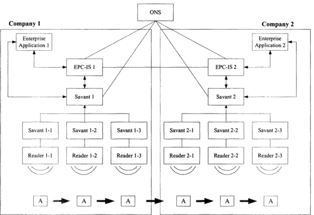
Regarding the system layout, we premise the structure in Figure 4-1-1. We assume two companies, and the difference is indicated by the suffix. We also assume that ONS is public so that both companies can use the ONS equally. Regarding Savant, we assume two layers. Savantl and Savant2 are connected to servers with EPC-IS (we represent these servers as EPC-IS in the system layout) and the enterprise application, and Savantl-1 - Savantl-3 and Savant2-1 - Savant2-3 are connected to readers and Savantl, Savant2 respectively. EPC-IS1 stores the property data of items and the historical data that is detected by Readerl1 Readerl3, whereas EPCIS2 stores the historical data that is detected by Reader21 -Reader2-3. The enterprise application controls business transaction data, such as purchase orders and advance ship notices, and also provides the interface for business process operations.
Figure 4-1-1: System layout for the generic business processes
4.2.
Query product-level data business process
4.2.1. Overview
Query product-level data business process is the business process that is executed when Company2 queries the product-level data of a product to Companyl's server (with EPC-IS) which stores the data of products. Preconditions of this business process are that these companies settle terms and conditions about this business process', original product data is stored in the Enterprise Applicationl, and Companyl and Company2 implement the Auto-ID infrastructure.
4.2.2. Business process flow
Figure 4-2-1 shows the flow of the business process. Each arrow represents the message sent between the system components.
IArticles that companies in the business process need to settle before the transactions are: the way to exchange business documents except for the messages we deal with, such as purchase order; the location of each Auto-ID compliant readers; and the technical specifications that are necessary to connect servers with EPC-IS, such as IP address.
1. Register product information: Original product-level data stored in the Enterprise Application l is sent to the EPC-IS1. When the data is registered successfully, an
acknowledgement message returns to the Enterprise Application 1.
2. Register EPC and the server to the ONS: The relation between the product-level EPC and the EPC-IS1 location is registered to the ONS. If the data is registered successfully, an acknowledgement message returns to the enterprise application. 3. Send EPC to a server of the trading partner: After the product-level information is
registered in the EPC-IS1, the data is sent to the EPC-IS2. Timing of the data update and the attributes of the product data may be defined in terms and conditions. When the data is sent successfully, an acknowledgement message returns to the EPC-IS1. 4. Send EPC from the EPC-IS2 to the Enterprise Application2: After the step 3, the
EPC-IS2 sends the EPC to the Enterprise Application2. When the data is sent successfully, an acknowledge message returns to the EPC-IS2. The data that the Enterprise Application2 receives depends on the data sent from the EPC-IS1, but the Enterprise Application2 can get the EPC at least. This message can be asynchronous to the step and 3. In this business process, we assume that sending a message from the EPC-IS2 to the Enterprise Application2, but this assumption is equivalent to the procedure that the Enterprise Application2 queries the EPC to the EPC-IS2.
5. Query the product-level data from the Enterprise Application2 to the EPC-IS2: After the step 4, the Enterprise Application2 has the product-level EPC of a specific product. Suppose an employee wants to know the size of the product, he operates the Enterprise Application2 and the Enterprise Application2 sends a query to the EPC-IS2.
6. EPC-IS look-up: After the step 5, the EPC-IS2 looks up the location of servers which store the data of a specific EPC by sending a query to the ONS. In this case, the EPC-IS2 gets the location information of the EPC-IS 1.
7. Query the product-level data from the EPC-IS2 to the EPC-ISI: After the step 6, the EPC-IS2 recognizes the location of the EPC-ISl. Then the EPC-IS2 queries the product-level data of a specific product to the EPC-ISI and gets the necessary information.
8. Response from the EPC-IS2 to the Enterprise Application2: In response to the step 5, the EPC-IS2 sends a response back to the Enterprise Application2. The response contains the data that the EPC-IS2 receives in the step 7.
E 4) 3 0o 0 0. a) , cL 0 a. w c c v,
4.3.
Query instance-level data business process
4.3.1. Overview
Query instance-level data business process is the business process that is executed when Company2 queries the instance-level data of a product to Companyl's server (with EPC-IS) which stores the instance-level property data. Preconditions of this business process are that these companies settle terms and conditions about this business process, original product data is stored in the Enterprise Applicationl, Company2 has already received the product level data and placed an order to Companyl, and they implement the Auto-ID infrastructure.
4.3.2. Business process flow
Figure 4-3-1 shows the flow of the business process. Each arrow represents the message sent between the system components.
1. Send the instance-level data with the EPC to the EPC-IS1: When each instance is scanned and the relevant data is inputted from one of the Savants, the data is sent to the EPC-IS1 from the Savantl. When the data is sent successfully, an acknowledge message returns to the Savant l.
2. Register the EPC and the server to the ONS: The relation between the instance-level EPC and the EPC-IS1 location is registered to the ONS. If the data is registered successfully, an acknowledgement message returns to the Savantl.
3. Send order information (order level) from the Enterprise Application 1 to the Savantl: Based on the order Companyl received from Company2, the Enterprise Applicationl sends an identifier of the purchase order, the product-level EPC and the quantity to the Savantl.2 When the data is sent successfully, an acknowledge message returns to the Enterprise Application 1.
4. Send order information (instance level) from the Savantl to the EPC-ISI: After the step 3, each order is linked with the individual EPC. Then the individual EPC with the relevant information (e.g., order identifier) is sent to the EPC-ISI and registered. When the data is sent successfully, an acknowledge message returns to the Savantl.
5. Query shipping information from the Enterprise Applicationl to the EPC-IS1: After
the step 4, the Enterprise Applicationl queries shipping information (EPC of item, case, pallet etc.) to send an advance ship notice to Company2. The key of the query is 2 We assume that Company2 assigns purchase order identifier and Companyl uses the same identifier. In the real practice, companies that receive purchase orders from their trading partner assign their own identifier, but they also maintain transform tables that link receiver's identifier with sender's identifier. We also assume that Companyl sends purchase order identifier that Company2 assigns when Companyl sends any messages related to the original purchase order.
the order identifier that the Enterprise Application 1 sends to the Savantl previously.
6. Send an advance ship notice to Company2: After the step 5, the Enterprise
Applicationl sends an advance ship notice to Company2. We assume the Enterprise Applicationl sends an advance ship notice to the EPC-IS1 and then the EPC-IS1 sends an advance ship notice to the EPC-IS2, but this information may be sent via EDI/B2Bi connection if they have a connection. We also assume the EPC-IS2 pushes an advance ship notice to the Enterprise Application2, but the Enterprise Application2 may query information to the EPC-IS2.
7. Query the instance-level data from the Enterprise Application2 to the EPC-IS2: After the step 6, the Enterprise Application2 has the instance-level EPC of the items that Company2 orders. Suppose an employee wants to know the expiration date of the individual item, he operates the Enterprise Application2 and the Enterprise Application2 sends a query to the EPC-IS2.
8. EPC-IS2 look-up: After the step 7, the EPC-IS2 looks up the location of servers which store the data of a specific EPC by sending a query to the ONS. In this case, the EPC-IS2 gets the location information of the EPC-IS 1.
9. Query the instance-level data from the EPC-IS2 to the EPC-IS 1: After the step 8, the EPC-IS2 recognizes the location of the EPC-IS1. Then the EPC-IS2 queries the instance-level data of a specific individual item to the EPC-IS1 and gets the information.
10. Response from the EPC-IS2 to the Enterprise Application2: In response to the step 7, the EPC-IS2 sends a response back to the Enterprise Application2. The response contains the data that the EPC-IS2 receives in the step 9.
c ao C'e oo.4) c) * LO C9 0 o 10 -D a) cin
4.4.
Query location data business process
4.4.1. Overview
Query location data business process is the business process that is executed when Company2 queries current location data of an individual item to the server which stores location data. Location data is stored in the server of Companyl, Company2 and the party which handles the item and stores the data. Preconditions of this business process are that these companies settle terms and conditions about this business process, original product data is stored in the Enterprise Applicationl, Company2 has already received product level data and placed an order to Companyl, and they implement the Auto-ID infrastructure.
4.4.2. Business process flow
Figure 4-4-1 shows the flow of the business process. Each arrow represents the message sent between the system components.
1. Send the instance-level data with the EPC to the EPC-ISI: When each instance is scanned and the relevant data is inputted from one of the Savants, the data is sent to the EPC-IS1 from the Savantl. When the data is sent successfully, an acknowledge message returns to the Savantl.
2. Register the EPC and the server to the ONS: The relation between the instance-level EPC and the EPC-IS1 location is registered to the ONS. If the data is registered
successfully, an acknowledgement message returns to the Savantl.
3. Send order information (order level) from the Enterprise Applicationl to the Savantl: Based on the order Companyl received from Company2, the Enterprise Applicationl sends an identifier of the purchase order, the product-level EPC and the quantity to the Savantl. When the data is sent successfully, an acknowledge message returns to the Enterprise Application 1.
4. Send the order information (instance level) from the Savantl to the EPC-IS1: After the step 3, each order is linked to the individual EPC. Then the individual EPC with the relevant information (e.g., order identifier) is sent to the EPC-IS1 and registered. When the data is sent successfully, an acknowledge message returns to the Savantl.
5. Query shipping information from the Enterprise Applicationl to the EPC-IS1: After
the step 4, the Enterprise Applicationl queries shipping information (EPC of item, case, pallet etc.) to send an advance ship notice to Company2. The key of the query is the order identifier that the Enterprise Application 1 sends to the Savant l previously. 6. Send an advance ship notice to Company2: After the step 5, the Enterprise
Application l sends an advance ship notice to the EPC-IS1 and then the EPC-ISI sends an advance ship notice to the EPC-IS2, but this information may be sent via EDI/B2Bi connection if they have a connection. We also assume the EPC-IS2 pushes an advance ship notice to the Enterprise Application2, but the Enterprise Application2 may query information to the EPC-IS2.
7. Send the detected data from the Savantl to the EPC-IS1: When the items are shipped, they are scanned by the readers and the data is sent from the Savantl to the EPC-IS1. In this sample process, we assume the Savantl-1 is located at Companyl's plant and the Savantl-2 and the Savantl-3 are located at the distribution center of Companyl. When they are scanned, the data is first sent from the Savantl-2 to the Savantl, and then the Savantl sends the data to the EPC-IS 1. When the data is sent successfully, an acknowledge message returns to the Sanvantl.
8. Query the instance-level data from the Enterprise Application2 to the EPC-IS2: After the step 6, the Enterprise Application2 has the instance-level EPC of the items that Company2 orders. Suppose an employee wants to know the location of the individual item, he operates the Enterprise Application2, and the Enterprise Application2 sends a query to the EPC-IS2.
9. EPC-IS2 look-up: After the step 8, the EPC-IS2 looks up the location of servers which store the data of a specific EPC by sending a query to the ONS. In this case, the EPC-IS2 gets the location information of the EPC-IS 1.
10. Query the instance-level data from the EPC-IS2 to the EPC-IS 1: After the step 9, the EPC-IS2 recognizes the location of the EPC-IS1. Then the EPC-IS2 queries the instance-level data (location data) of a specific individual item to the EPC-IS 1 and gets the information.
11. Response from the EPC-IS2 to the Enterprise Application2: In response to the step 8, the EPC-IS2 sends a response back to the Enterprise Application2. The response contains the data that the EPC-IS2 receives in the step 10.
cr c -o Gt o Eu
4.5.
Query path data business process
4.5.1. Overview
Query path data business process is the business process that is executed when Company2 queries the path data that an individual item takes by using the EPC that is originally sent by Companyl. The event data is stored by the servers of Companyl, Company2 and the other parties which handle the item. With this business process, Company2 can retrieve EPC of readers that have scanned the specific instances, and, from EPCs of these readers and the location information of them, which are received by Company2 in terms and conditions, Company2 can trace the physical route that these instances have taken. Preconditions of this business process are that these companies settle terms and conditions about this business process, original product data is stored in the Enterprise Applicationl, Company2 has already received the product level data and placed an order to Companyl, and they implement the Auto-ID infrastructure.
4.5.2. Business process flow
Figure 4-5-1 shows the flow of the business process. Each arrow represents the message sent between the system components.
1. Send the instance-level data with the EPC to the EPC-IS1: When each instance is scanned and the relevant data is inputted from one of the Savants, the data is sent to the EPC-IS1 from the Savantl. When the data is sent successfully, an acknowledge message returns to the Savant l.
2. Register the EPC and the server to the ONS: The relation between the instance-level EPC and the EPC-ISI location is registered to the ONS. If the data is registered successfully, an acknowledgement message returns to the Savantl.
3. Send order information (order level) from the Enterprise Applicationl to the Savantl: Based on the order Companyl received from Company2, the Enterprise Application Il sends an identifier of the purchase order, the product-level EPC and the quantity to the Savantl. When the data is sent successfully, an acknowledge message returns to the Enterprise Application 1.
4. Send order information (instance level) from the Savantl to the EPC-ISI: After the step 3, each order is linked to the individual EPC. Then the individual EPC with the relevant information (e.g., order identifier) is sent to the EPC-IS1 and registered. When the data is sent successfully, an acknowledge message returns to the Savantl.
5. Query shipping information from the Enterprise Applicationl to the EPC-ISI: After the step 4, the Enterprise Applicationl queries shipping information (EPC of item, case, pallet etc.) to send an advance ship notice to Company2. The key of the query is
the order identifier that the Enterprise Application 1 sends to the Savantl previously.
6. Send an advance ship notice to Company2: After the step 5, the Enterprise
Application l sends an advance ship notice to Company2. We assume the Enterprise Applicationl sends an advance ship notice to the EPC-IS1 and then the EPC-ISI sends an advance ship notice to the EPC-IS2, but this information may be sent via EDI/B2Bi connection if they have a connection. We also assume that the EPC-IS2 pushes an advance ship notice to the Enterprise Application2, but the Enterprise Application2 may query new information to the EPC-IS2.
7. Send detected data from the Savant to the server: When the items are shipped, they are scanned by the readers and the data is sent from Savant to the servers. In this sample process, we assume the Savantl-1, the Savantl-2, and the Savantl-3 are located at Companyl's facility and the Savant2-1, the Savant2-2 and the Savant2-3 are located at Company2's facility. All these Savants are called edge Savant. When scanned, the data is first sent from the edge Savant to the Savantl or the Savant2, and then each Savant sends the data to the server with EPC-IS in the facility. When the data is sent successfully, an acknowledge messages return to the Savants which send the message to each server.
8. Register the EPC and the server to the ONS: The relation between the instance-level EPC and the EPC-IS2 location is registered to the ONS at Company2 side. If the data is registered successfully, an acknowledgement message returns to the Savant2.
9. Query the instance-level data from the Enterprise Application2 to the EPC-IS2: After the step 6, the Enterprise Application2 has the instance-level EPC of the items Company2 orders. Suppose an employee wants to know the path that the individual item takes, he operates the Enterprise Application2 and the Enterprise Application2 sends a query to the EPC-IS2.
10. EPC-IS2 look-up: After the step 9, the EPC-IS2 looks up the location of severs which store the data of a specific EPC by sending a query to the ONS. In this case, the EPC-IS2 gets the location information of the EPC-IS I and the EPC-IS2 itself.
11. Query the instance-level data from the EPC-IS2 to the EPC-IS1: After the step 10, the EPC-IS2 recognizes the location of the EPC-IS1. Then the EPC-IS2 queries the instance-level data of a specific individual item to the EPC-IS1 and gets the information.
12. Response from the EPC-IS2 to the Enterprise Application2: In response to the step 9, the EPC-IS2 sends a response back to the Enterprise Application2. The response contains both path data that the EPC-IS2 receives in the stepll and path data the EPC-IS2 stores.
cl It 'e a 5: rcl 0o o o 4. 0 0 0 ' 01) U,
4.6.
Exceptions
4.6.1. Overview
In addition to the generic business processes, we include exception business processes. We assume two types of exceptions: exceptions that happened after a system component received a notify message, and exceptions that happened after a system component received a query message. We exclude the exceptions that happen on account of the messaging protocol layer and the lower layer errors.
4.6.2. Business process flow for notify exception
Figure 4-6-1 shows the flow of the business process. Each arrow represents the message sent between the system components.
1. Register the product information: Original product-level data stored in the Enterprise Applicationl is sent to the EPC-IS1. When the data is registered successfully, an acknowledgement message returns to the Enterprise Application 1.
2. Register the EPC and the server to the ONS: The relation between the product-level EPC and the EPC-IS1 location is registered to the ONS. If the data is registered successfully, an acknowledgement message returns to the enterprise application. 3. Send the EPC to the server of the trading partner: After the product-level information
is registered in the EPC-IS 1, the data is sent to the EPC-IS2. Here we assume a case that the data is sent to the EPC-IS2, but the EPC-IS2 does not register the data for some reason. The EPC-IS2 sends an exception message back to the EPC-IS1, and the EPC-IS1 sends an exception message to the original requester, the Enterprise Applicaiton 1.3
4.6.3. Business process flow for query exception
Figure 4-6-2 shows the flow of the business process. Each arrow represents the message sent between the system components.
1. Register the product information: Original product-level data stored in the Enterprise Application 1 is sent to the EPC-IS1. When the data is registered successfully, an
acknowledgement message returns to the Enterprise Application 1.
3 We see the necessity of another message that deals with recovering the data integrity after an exception occurs, but we exclude this issue out of the thesis's scope.
2. Register the EPC and the server to the ONS: The relation between the product-level EPC and the EPC-IS 1 location is registered to the ONS. If the data is registered successfully, an acknowledgement message returns to the enterprise application.
3. Send the EPC to a server of the trading partner: After the product-level information is registered in the EPC-IS 1, the data is sent to the EPC-IS2. Timing of the data update and the attributes of the product data may be defined in terms and conditions. When the data is sent successfully, an acknowledgement message returns to the EPC-IS 1.
4. Send the EPC from the EPC-IS2 to the Enterprise Application2: After the step 3, the EPC-IS2 sends the EPC to the Enterprise Application2. When the data is sent successfully, an acknowledge message returns to the EPC-IS2. The data that the Enterprise Application2 receives depends on the data sent from the EPC-IS1, but the Enterprise Application2 can get the EPC at least. This message can be asynchronous to the step 1 and 3. In this business process, we assume that sending a message from the EPC-IS2 to the Enterprise Application2, but this assumption is equivalent to the procedure that the Enterprise Application2 queries the EPC to the EPC-IS2.
5. Query the product-level data from the Enterprise Application2 to the EPC-IS2: After the step 4, the Enterprise Application2 has the product-level EPC of a specific product. Suppose an employee wants to know the size of the product, he operates the Enterprise Application2 and the Enterprise Application2 sends a query to the EPC-IS2.
6. EPC-IS look-up: After the step 5, the EPC-IS2 looks up the location of servers which store the data of a specific EPC by sending a query to the ONS. In this case, the EPC-IS2 gets the location information of the EPC-IS 1.
7. Query the product-level data from the EPC-IS2 to the EPC-IS1: After the step 6, the EPC-IS2 recognizes the location of the EPC-IS1. Then the EPC-IS2 queries the product-level data of a specific product to the EPC-IS 1. Here we assume a case that the query is sent to the EPC-IS 1, but the EPC-IS 1 does not retrieve the data for some reason. The EPC-IS2 sends an exception response message back to the EPC-IS2, and the EPC-IS2 sends an exception response message back to the original requester, the Enterprise Applicaiton2.
0 c o a) 0 o. :: Fa __
0 a. w a) L U) E3 a 0 o. ._ 00 LC 0 r+. -L-1
4.7.
Requirement definition
From the generic business processes we defined in the previous section, we distill the requirements for EPC-IS interface.
4.7.1. Message types
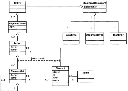
From the generic business processes, we find that three types of messages are necessary for EPC-IS: Notify message, Query/Response message, and Acknowledge message. The Notify message is used when the Enterprise Application, Savant, EPC-IS or other Auto-ID compliant components create the data that is supposed to be stored in the server with EPC-IS. This message is also used when these software components ask servers with EPC-IS for transferring another Notify message with additional data stored in the servers. It is used for both property data and historical data, and can send data of multiple products and instances.
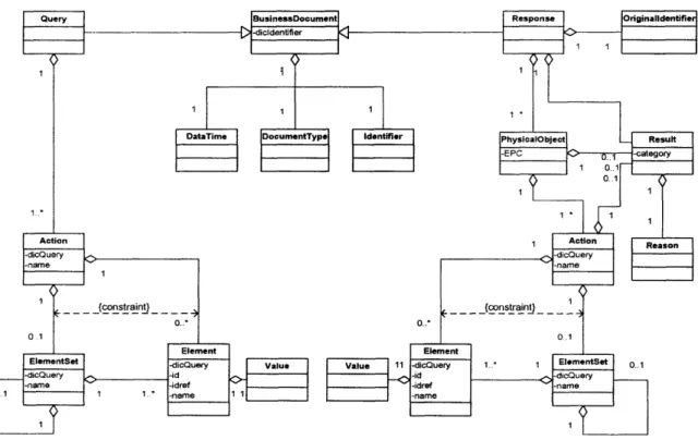
The Query message is used when the Enterprise Application, EPC-IS or other Auto-ID compliant components query the data to servers with EPC-IS, and Response message is the response to the query. The key for the query may be EPC, property data, date time stamp of historical data, and any other data defined in the message exchange.
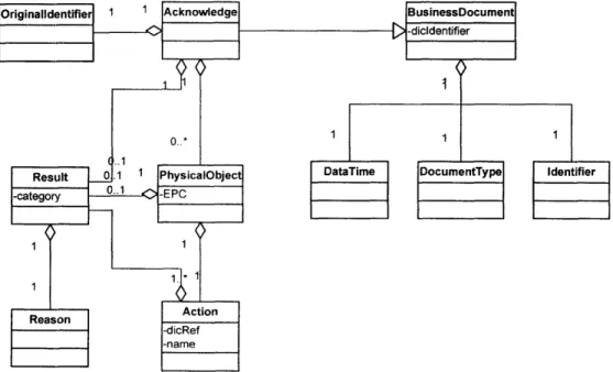
The Acknowledge message is used to acknowledge the receipt of the Notify message. A sending system component uses the Acknowledge message to confirm that the Notify message has arrived at the receiving component. However, the use depends on the business context. The message may send either message level result or the product/instance level result.
4.7.2. Scalability of the message
Although four generic business processes are based on the RFID implementation trials and the expected business processes of RFID, they do not cover all the business processes with EPC-IS. Therefore, the model needs to have scalability to accommodate other business processes and future business processes.
4.7.3. Data type
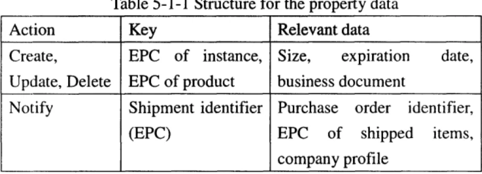
From the generic business processes, we find that EPC-IS must be able to deal both property data and historical data, and the property data consists of product-level property data and instance-level property data.
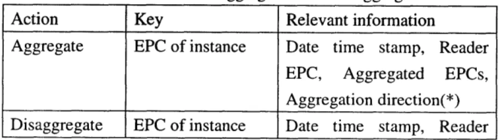
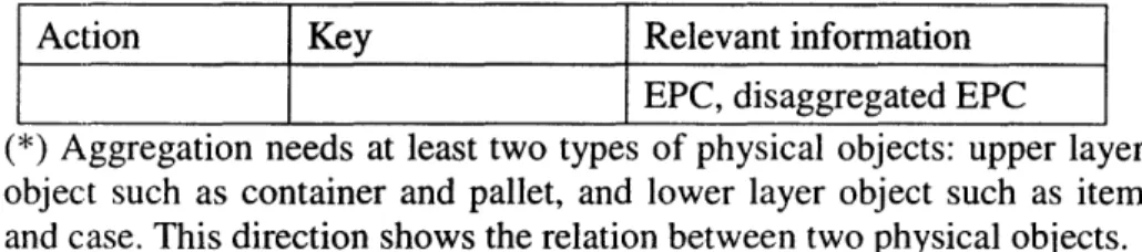
Actions required from the property data are create, update and query, but it is conceivable that delete action is necessary as well. The historical data is stored when an event occurs to each individual item. Attributes which need to be stored are event type, EPC of the subjected item, date time stamp, and the relevant data, such as reader EPC.