https://doi.org/10.4224/20374076
READ THESE TERMS AND CONDITIONS CAREFULLY BEFORE USING THIS WEBSITE. https://nrc-publications.canada.ca/eng/copyright
Vous avez des questions? Nous pouvons vous aider. Pour communiquer directement avec un auteur, consultez la
première page de la revue dans laquelle son article a été publié afin de trouver ses coordonnées. Si vous n’arrivez pas à les repérer, communiquez avec nous à [email protected].
Questions? Contact the NRC Publications Archive team at
[email protected]. If you wish to email the authors directly, please see the first page of the publication for their contact information.
NRC Publications Archive
Archives des publications du CNRC
For the publisher’s version, please access the DOI link below./ Pour consulter la version de l’éditeur, utilisez le lien DOI ci-dessous.
Access and use of this website and the material on it are subject to the Terms and Conditions set forth at Method for testing portable air cleaners
Sultan, Z. M.; Nilsson, G.; Magee, R. J.; Bradley, J. S.
https://publications-cnrc.canada.ca/fra/droits
L’accès à ce site Web et l’utilisation de son contenu sont assujettis aux conditions présentées dans le site LISEZ CES CONDITIONS ATTENTIVEMENT AVANT D’UTILISER CE SITE WEB.
NRC Publications Record / Notice d'Archives des publications de CNRC: https://nrc-publications.canada.ca/eng/view/object/?id=cc1570e0-53cc-476d-b2ee-3e252d8bd739 https://publications-cnrc.canada.ca/fra/voir/objet/?id=cc1570e0-53cc-476d-b2ee-3e252d8bd739
http://www.nrc-cnrc.gc.ca/irc
M e t hod for T e st ing Port a ble Air Cle a ne rs
N R C C - 5 4 0 1 3
S u l t a n , Z . M . ; N i l s s o n , G . ; M a g e e , R . J . ; B r a d l e y , J . S .
A p r i l 2 0 1 1
A version of this document is published in / Une version de ce document se trouve dans:
Prepared for: Government of Canada, Clean Air Agenda, Indoor Air Initiative - Evaluation of IAQ Solutions in Support of Industry Innovation, pp. 1-43, March 23, 2011
The material in this document is covered by the provisions of the Copyright Act, by Canadian laws, policies, regulations and international agreements. Such provisions serve to identify the information source and, in specific instances, to prohibit reproduction of materials without written permission. For more information visit http://laws.justice.gc.ca/en/showtdm/cs/C-42
Les renseignements dans ce document sont protégés par la Loi sur le droit d'auteur, par les lois, les politiques et les règlements du Canada et des accords internationaux. Ces dispositions permettent d'identifier la source de l'information et, dans certains cas, d'interdire la copie de documents sans permission écrite. Pour obtenir de plus amples renseignements : http://lois.justice.gc.ca/fr/showtdm/cs/C-42
Method for Testing Portable Air Cleaners
Zuraimi Sultan, Gregory Nilsson, Robert Magee, John Bradley
Prepared for: Government of Canada, Clean Air Agenda, Indoor Air Initiative - Evaluation of IAQ Solutions in Support of Industry Innovation
Technical Advisory Committee
Zuraimi M Sultan, Chair National Research Council Canada Ali Bahloul Institut de recherche Robert-Sauvé en Santé et en Sécurité du Travail
Prabjit Barn BC Centre for Disease Control
Glenn Curtis Heating, Refrigeration & Air-Conditioning Institute of Canada Regina De La Campa Canada Mortgage and Housing Corporation Eomal Fernando Canadian Standards Association (CSA) - International
Don Figley Figley Consulting Associates Ltd
Don Fugler Canada Mortgage and Housing Corporation
Gemma Kerr InAIR Environmental Ltd
Robert Magee National Research Council Canada
Gregory Nilsson National Research Council Canada
Brian Stocks Ontario Lung Association
Michel Tardif Natural Resources Canada
Aaron Wilson Health Canada
Connie Wong Ontario Lung Association
Notice
This protocol test method is developed by the National Research Council Canada (NRC) to assess the initial performance of portable air cleaners of any technology. It is prepared by NRC researchers under the guidance of the Technical Advisory Committee (TAC) whose members are participants representing Federal and Provincial Agencies, Industry Associations, Non-Governmental Organizations (NGOs), Municipal governments, and Standards Associations from Canada. Compliance to this protocol test method is voluntary until and unless a jurisdiction makes compliance mandatory through legislation. This protocol test method may serve as a base document for the development of standard or guideline document.
NRC, including its members and the TAC, does not make any warranty, expressed or implied, and does not assume any legal responsibility for the accuracy of any information or for completeness or usefulness of any apparatus, product or process disclosed, or accept liability for the use, or damages resulting from the use, thereof. NRC, including its members and the TAC, hereby disclaim any and all warranties, expressed or implied, including the warranties of merchantability and fitness for a particular purpose, whether arising by law, custom or conduct, with respect to any of the information in this protocol. In no event shall NRC be liable for incidental or consequential damages because of use of any information contained in this protocol.
This protocol test method is developed under the best efforts for the benefit of the public in light of available information and best industry practices. However, NRC, including its members and the TAC, do not guarantee, certify or assure the safety performance of any products, components or systems tested, installed or operated in accordance to this protocol test method or that any tests conducted under this protocol test method will be nonhazardous or free from risk.
Reference in this protocol to any specific commercial product, process or service by tradename, trademark, manufacturer or otherwise does not necessarily constitute or imply its endorsement or recommendation by NRC, its members or the TAC.
TABLE OF CONTENTS
1 INTRODUCTION 5
1.1 Purpose 5
1.2 Scope 5
1.3 Overview of Test Method 5
2 DEFINITIONS AND ACRONYMS 7
2.1 Definitions 7
2.2 Acronyms and Abbreviations 9
2.3 Referenced Documents 10
3 TEST APPARATUS 12
3.1 Test Chamber for IAQ Performance 12
3.2 Test Chamber for Acoustic Performance 13
3.3 Test Apparatus for Particles 14
3.3.1 Particle Generation 15 3.3.2 Particle Measurement 15
3.4 Test Apparatus for VOCs 16
3.4.1 VOC Generation 16 3.4.2 VOC Measurement 17
3.5 Test Apparatus for Acoustic Measurements 18
3.6 Test Environment Monitoring and Data Acquisition System for IAQ
Performance 18 3.6.1 Temperature 18 3.6.2 Relative Humidity 18 3.6.3 Air Velocity 19 3.6.4 Ozone 19 3.6.5 Chamber Mixing 19 3.6.6 Air Exchange Rate 19 3.6.7 Data Acquisition System 19
4 BACKGROUND CONDITIONS FOR IAQ PERFORMANCE 20
4.1 System Qualification and Calibration 20
4.2 Conditions for Measurement 20
5 TEST PROCEDURE FOR DETERMINING PERFORMANCE 22
5.1 IAQ Performance Test 22
5.1.1 Portable Air Cleaner Emissions and By-product Formation 22
5.1.2 Portable Air Cleaner Particle and VOC Removal 24
5.2 Sound Power Level Measurements 28
5.3 Electrical Power Measurements 29
5.3.1 Electrical Operating Power Measurements 29 5.3.2 Electrical Standby Power Measurements 29
5.4 Air Flow Rate Measurements 29
6 CALCULATION PROCEDURES 30
6.1 Calculating the First Order Decay Constant 30
6.2 Calculating the Correlation Coefficient 31
6.3 Calculating the Standard Deviation 32
6.4 Calculating the CADR 32
6.5 Calculating the Standard Deviation of CADR 33
6.6 Ozone First Order Decay Constant Calculation 34
7 PAC PERFORMANCE AND RATING 34
7.1 PAC Emissions and By-product Formation Rating 34
7.1.1 Ozone 34
7.1.2 VOC 35
7.1.3 Net Particle Emission Rates Calculation 36
7.2 Portable Air Cleaner Particle and VOC Removal 37
7.2.1 Particle Removal Rates (PRR) 37 7.2.2 VOC Single Pass Efficiency (SPE) 38
7.3 Energy Efficiency Index 38
7.4 PAC Acoustic Performance Rating 38
8 REPORTING OF THE TEST RESULTS 40
9 EFFECTIVENESS AND ROOM DIMENSIONS FOR PAC USE 40
1 Introduction 1.1 Purpose
This protocol establishes a test procedure for evaluating the performance of portable air cleaning (PAC) devices intended primarily for residential environments. The PAC device may utilize various media/technologies (singly or in combination) intended for capture of particles and/or specific gaseous contaminants. By testing the PAC units under standardized conditions which reflect actual usage, the results of these tests are expected to 1) assist manufacturers in the design, improvement and innovation in PAC production, and 2) provide a foundation for scientifically-sound PAC labeling systems by which consumers can evaluate a device’s claimed indoor air quality (IAQ) impact.
1.2 Scope
This protocol describes a method for evaluating the particle and gaseous contaminant removal performance of portable air cleaners used primarily in residential settings with mixing-type ventilation systems. A portable air cleaner (PAC) is defined as an energy-consuming device (including battery operated versions) used to reduce the concentration of airborne pollutants, including but not limited to dusts, particles, environmental tobacco smoke, allergens, micro-organisms (e.g., mold, bacteria, pollen, viruses, and other bioaerosols), fumes, gases or vapors and odorous chemicals from the indoor air of a residential space. PAC technologies include, but are not limited to, mechanical air cleaners (e.g. HEPA filters), electrically charged filters, electrostatic precipitators, ionizers, photocatalytic oxidation, plasma-cluster ion, ozone generators, activated carbon (with and without chemical impregnated compounds) filters and others. PACs include devices of any size used for cleaning the air in a residential room of any size or in a whole house which could be stand-alone devices designed as wall-, floor-, ceiling-, table-, combination- or plug-in types.
1.3 Overview of Test Method
This protocol addresses portable air cleaner performance characteristics of importance to users: the ability of the device to remove particles and selected gaseous contaminants from an unoccupied room, evaluation of their emissions and by-product formations, acoustic properties and energy consumption. The four principles behind the test method are; 1) uniformity: results can be used to directly compare devices on a standardized basis irrespective of their application; 2) realistic: test conditions represent realistic indoor contaminant loads under typical environmental conditions; 3) flexibility: apply to diverse classes of room air cleaning devices and 4) comprehensive: cover critical test aspects in terms of by-products generation of some classes of devices, energy consumption and noise reduction.
For the IAQ performance, PACs are evaluated for their emissions and by-product formation as well as particle and VOC removal. A standard emissions test performed
under steady state conditions will be used to determine the PACs emissions of selected pollutants and their by-product formation. For PAC particle and VOC removal, a “pull-down” method will be used to conduct the test (AHAM, 2006; Chen et al., 2005). Figure 1 shows the general schematic of the test method. Each test phase (gaseous or particulate contaminant removal tests) consists of two portions: 1) challenge injection phase and 2) decay condition phase. Known amount of particles of different sizes or selected VOCs are introduced (in different tests) during the challenge injection phase to achieve the desired target concentrations. Once target contaminant levels in the test chamber have been achieved, the challenge injection is stopped, and the concentration decay rate from the decay condition is measured. By repeating the test, with and without the PAC operating, the removal effectiveness of the unit can be determined from the difference in the 2 curves shown in Figure 1. The performance indices of the device for each VOC and different size particles using this test method are single pass efficiency (SPE) and the clean air delivery rate (CADR).
0 1,000 2,000 3,000 4,000 5,000 0.0 0.5 1.0 1.5 2.0 2.5
Pa
rt
ic
le
Co
nc
en
tr
at
io
n
(no
/m
3)
Time (Hour) PAC ON PAC OFFFigure 1 Time-concentration profile for a ‘pull-down’ test method.
The test is to be performed under full recirculation mode (chamber operated as closed system) to facilitate comparison with other test methods (AHAM, 2006). Particles and VOC removal performances and by-product emissions are to be performed at environmental conditions of air temperature 21.0 ± 2 0C, relative humidity (RH) 40 ± 5 % and chamber air exchange rate less than 0.05 air change per hour.
For acoustic measurements, the experiments are to be conducted in a reverberant test chamber that conforms to the requirements of the ISO 3743-1 method (ISO, 1999). The comparison procedure for determining the sound power of a test source to an ‘engineering’ grade of precision described in ISO 3743-1 is to be adopted. This requires the comparison of measurements of the PAC source with those of a reference sound source, such as the ILG reference sound source. The reference source must have been calibrated to a ‘precision’ grade according to ISO 3741 and must meet all of the requirements in ISO 6926 for reference sound sources.
The electrical power measurements are to be conducted under PAC running and standby modes.
2 Definitions and Acronyms 2.1 Definitions
Key terms are defined below for the purposes of this protocol. adsorbent: a material that collects sorbates by adsorption.
adsorption: the attraction of a sorbate to the surface, both outer surface and inner pore surface, of a media by physical forces (Van der Waals forces). This is a reversible process.
aerodynamic particle sizer: an instrument capable of measuring aerodynamic particle size distribution from 0.5 μm to 5 μm diameter relevant for this protocol. The instrument also provides the total particle number concentration between this size ranges and is hereby defined as “total APS”.
air flow rate (chamber): the volumetric flow rate at test chamber supply and return diffusers.
air flow rate (device): the volumetric flow rate out of the supply inlet.
bypass: the proportion of the challenge particle, gas or vapor that passes around the filtration media bed or the device without contacting the media or the device itself.
byproduct: compounds formed as a result of the heterogeneous and homogeneous reactions of ozone and photocatalytic oxidation (PCO).
challenge particle: the airborne particle generated via nebulised NaCl solution having particle sizes detected from 0.05 μm to 10 μm diameter.
challenge VOCs: the 3 volatile organic compounds that are generated as the chemical contaminants of interest.
chamber: a room-size chamber that can house the portable air cleaners to be tested for their IAQ and acoustic performance and provide the required environmental conditions that are similar to portable air cleaners use in full-scale room conditions.
clean air delivery rate: the main index for assessing performance of portable air cleaners. It is the product of the device single pass efficiency (SPE) with the device air flow rate and defined as the delivery of contaminant free air by a device measured in cubic meters per hour (m3/hr).
coarse particles: relatively large airborne particles with aerodynamic diameter ranging from 2.5 µm to 10 µm.
comparison method: the method in which the sound power level of a device under test is determined by comparing the averaged value (on a mean square basis) of the sound pressure levels produced by the device in a test chamber to the averaged value of the sound pressure levels produced in the same chamber by a reference sound source of known sound power output. The difference in sound pressure levels is equal to the difference in sound power levels when conditions are the same for both sets of measurements.
device: throughout this protocol the word “device” means portable air cleaner (PAC) used in general for the removal of particles and gas-phase contaminants, specifically, the portable air cleaner being tested.
effectiveness: describes the impact of device operation on room air concentrations under steady state conditions. It is bounded by zero and one, with zero indicating a completely ineffective air cleaner (0% of the pollutants are removed) and one indicating a perfectly effective air cleaner (100% of the pollutants are removed).
emissions: the mass of contaminants emitted from the portable air cleaners in the space per unit time (mg/h). For VOCs and particles, the emissions are determined two conditions: 1) with the portable air cleaners turned off and 2) with the portable air cleaners turned off. For ozone, the emissions are determined with the portable air cleaners turned on.
fine particles: airborne particles which are smaller than coarse particles. They have an aerodynamic diameter between 0.1 and 2.5 µm
generator: the instruments which produce challenge VOCs and particles at concentrations sufficiently meeting the requirements of the protocol.
natural decay: the reduction of particles or VOCs due to natural processes (i.e. surface deposition, sink effects, air exchange) in the chamber.
net emission rate: the mass of contaminants emitted from the portable air cleaners in the space per unit time (mg/h) taking into account other removal processes.
operating electrical power: the average electrical power in device operation mode, measured in Watts.
particle diameter: the diameter of a sphere of unit density (1g/cc) that has the same gravitational settling velocity as the particle in question. A particle's aerodynamic diameter affects penetration depth in the human respiratory tract, capture efficiency by a filter, as well as transport behavior and suspension times in indoor environments.
polydisperse: a characteristic of an aerosol for which the width of its number distribution shows a geometric standard deviation of δg> 1.5
portable air cleaner: A transportable electric appliance with the function of removing particles and gas-phase contaminants from the indoor air.
reference sound source: a stable sound source emitting steady, broad-band noise with adequate sound power over a wide frequency range, calibrated in accordance to with ISO 6926.
room size: the maximum room size for effective portable air cleaner use.
scanning mobility particle sizer: an instrument capable of measuring particle size distribution from 0.05 µm to 0.5 µm diameter relevant for this protocol. The instrument also provides the total particle number concentration between this size ranges and is hereby defined as “total SMPS”.
single pass efficiency (SPE): that fraction of challenge particles / gas molecules which is removed by the device.
sorption: a process in which fluid molecules (gas or liquid) are removed by a media by absorption or adsorption.
sound power level: the rate of acoustic energy emitted from the device at maximum setting measured in decibels (dB).
standby mode: The lowest electrical power consumption mode which cannot be
switched off by the user and that may persist for an indefinite time when a device is connected to the main electricity suppy.
standby electrical power: the average electrical power in device standby mode, measured in Watts.
steady state: a condition where measurement concentrations do not fluctuate greater than ± 10% during a 30 minute period.
ultrafine particles: airborne particles which are smaller than fine particles. They have a diameter that is less than 0.1 µm
2.2 Acronyms and Abbreviations ACH Air change per hour
ALTER Acceptable long-term exposure range
ASHRAE American Society for Heating, Refrigerating and Air-conditioning Engineers
AHAM Association of Home Appliance Manufacturers ANSI American National Standards Institute
APS Aerodynamic particle sizer
ASTM American Society for Testing and Materials CADR Clean air delivery rate
CCHT Canadian Centre for Housing Technology CPC Condensation particle counter
CSA Canadian Standards Organization DAS Data acquisition system
DNPH 2-4 dinitrophenyl hydrazine DMA Differential mobility analyser EEI Energy efficiency index
EPA United States Environmental Protection Agency ESP Electrostatic precipitator
ETS Environmental tobacco smoke
GC Gas chromatograph
GCMS Gas chromatograph mass spectrometer
HC Health Canada
HCHO Formaldehyde
HEPA High efficiency particulate air
HPLC High performance liquid chromatography HVAC Heating, ventilating and air-conditioning IAQ Indoor Air Quality
ILG RSS ILG reference sound source
ISO International Organization for Standardization KCl Potassium chloride
LIM d-limonene
NRC National Research Council Canada NaCl Sodium chloride
O3 Ozone
OP Operating electrical power OPC Optical particle counters PAC Portable air cleaner
PCI Plasmacluster ion
PCO Photocatalytic oxidation PRR Particle removal rates
ppb Parts per billion by volume ppm Parts per million by volume
PTFE Teflon or Polytetrafluoroethylene RH Relative humidity (%)
RR Removal rates
SPE Single pass efficiency TOL Toluene
TFE Teflon or PTFE (see PTFE) UFP Ultrafine particles UV Ultraviolet light
UVGI Ultraviolet germicidal irradiation UV-VIS Ultraviolet –visible light
VOC Volatile organic compounds ε Effectiveness
2.3 Referenced Documents
ANSI/AHAM AC-1-2006 Method for Measuring Performance of Portable Household Electric Room Air Cleaners.
ANSI/ASHRAE Standard 129 1997. Test method for air change effectiveness.” American Society of Heating, Refrigerating and Air-conditioning Engineers, Inc., Atlanta, Georgia.
ASTM D 5197-09 Test Method for “Determination of Formaldehyde and Other Carbonyl Compounds in Air (Active Sampler Methodology)”
ASTM D 6196 – 03 (Reapproved 2009) Standard Practice for Selection of Sorbents, Sampling, and Thermal Desorption Analysis Procedures for Volatile Organic Compounds in Air
ASTM D 6670 – 01 (Reapproved 2007) Standard Practice for Full-Scale Chamber Determination of Volatile Organic Emissions from Indoor Materials/Products
ASTM E 471-00 Test Method for “Determining Air Change in a Single Zone by Means of a Tracer Gas Dilution” (ASTM, 2006)
Bhangar S, Mullen NA, Hering SV, Kreisberg NM, Nazaroff WW Ultrafine particle concentrations and exposures in seven residences in northern California. Indoor Air 2011, 21(2): 132-44.
Bradley J (1986) Acoustical Measurements in Some Canadian Homes. Canadian Acoustics 14, 4, 14.
CSA 22.2 No. 187 (3rd Edn, Mar.2009) Electrostatic air cleaners. Health Canada (1989): Exposure Guidelines for Residential Indoor Air Quality.
CSA PLUS 14021 - Environmental Claims: A guide for Industry and Advertisers UL 867 (4th Edn, 2000, revised 2007) Electrostatic air cleaners
Chen W, Zhang JS, Zhang Z. Performance of air cleaners for removing multiple volatile organic compounds in indoor air. ASHRAE Trans 2005, 111: 1101-14. Gilbert NL, Gauvin D, Guay M, Héroux M-E, Dupuis G, Legris M, Chan CC, Dietz RN, Lévesque B. Housing characteristics and indoor concentrations of nitrogen dioxide and formaldehyde in Quebec City, Canada. Environmental Research 2006, 102(1): 1-8
Gilbert NL, Guay M, Miller JD, Judek S, Chan CC, Dales RE. Levels and determinants of formaldehyde, acetaldehyde, and acrolein in residential indoor air in Prince Edward Island, Canada. Environmental Research 2005, 99(1): 11-7. ISO 3741:1999 Acoustics -- Determination of sound power levels of noise sources
using sound pressure -- Precision methods for reverberation rooms
Liu LJ, Koutrakis P, Leech J, Broder I. Assessment of ozone exposures in the greater metropolitan Toronto area. Journal of Air & Waste Management Association 1995, 45: 223–34.
Miller-Leiden S, Lobascio C, Nazaroff WW, Macher JM. Effectiveness of in-room air filtration and dilution ventilation for tuberculosis infection control. Journal of Air & Waste Management Association 1996. 46(9): 869-82.
Nel A. Atmosphere. Air pollution-related illness: effects of particles. Science 2005, 308:804–6
Otson O, Fellin P, Tran Q VOCs in representative Canadian residences. Atmospheric Environment 1994, 28(22), 3563-69.
Reardon J. (2007) Assessment of Natural Ventilation for Canadian Residential Buildings. Client Report B-3316.1a Institute for Research in Construction, National Research Council of Canada
Weschler CJ. Ozone in indoor environments: concentration and chemistry. Indoor Air 2000, 10(4): 269-88.
NRC, Canadian Centre for Housing Technology (CCHT) internal data. Wallace LA (2009) Ultrafine Particles: A Review. Report for Health Canada.
3 Test Apparatus
3.1 Test Chamber for IAQ Performance
The considerations for room size chamber in determining performance of removing VOCs and particles and by-product emissions are given below. The chamber should be made from inert materials and fully characterized and its performance tested according to guidance provided in ASTM D6670. The following are key elements of suitable chamber design:
Control: The chamber system should be able to provide accurate control of airflow rate, temperature, relative humidity, pressure and background levels of particles, VOCs and ozone. The range of control conditions considered is typical for residential rooms found in Canadian buildings.
Inert: The chamber system and its apparatus should not generate particles and VOCs in the interior. Further, adsorption VOCs within the interiors should be minimal.
Airtightness: The chamber system should be airtight to reduce ambient air infiltration into the chamber and exfiltration out of chamber air.
Airflow: The chamber system should be able to simulate air velocities, flow patterns, and air distribution that are found typically in real ventilated residential room with mixing-type ventilation systems. Chamber mixing should be evaluated with and without the presence of the operating PAC device.
Monitoring: The chamber system should be able to provide on-line and remote monitoring/operation of the test conditions including airflow rates, air temperature, relative humidity, particles and VOCs generation and measurements, pressure inside the chamber and within the ventilation ducts. The remote monitoring/operation of the chamber should ensure that during the conduct of the test, it would not require a person to enter the chamber
Ports: The chamber system should have adequate ports for sampling and power and communication cables within the chamber. Also, there should be adequate ports in the ventilation ducts for air flow measurements.
Maintenance: The chamber system should be easily accessible for cleaning and maintenance.
Modular Design: The chamber system should be able to simulate typical residential room design layout.
Table 1 Chamber specifications for environmental conditions
Specification Control Range Control Precision Reference
Air flow rates 2.5 to 142 L/s ±3.0 % 1
Air exchange rates 0.05a to 1.0 ACH ±3.0 % 1
Temperature 17 to 27 0C ±0.5 0C 2, 3
Relative Humidity 20 to 60 % ±5.0 %RH 2, 3
a Total air leakage in 100% recirculation.
[1] Reardon (2007) [2] Gilbert et al. (2006) [3] NRC, CCHT internal data.
NRC’s “full scale chamber”, used in the development of this method, has inside dimensions of 5.0 x 4.0 x 2.75m (Volume: 55m3). The envelope (from the interior) is comprised of 11 gage stainless steel sheets for the floor and 14 gage for the ceiling and walls Type 304, No. 4 surface finish stainless steel sheets, 100 mm fibreglass insulation, and 12,7 mm plywood. The stainless steel, floor, ceiling and walls of the test chamber are welded together. A stainless steel pass through panel at the side of the chamber has adequate connectors for power, communications and sampling cables for remote control. The door of the test chamber is 1.45 x 1.93 m and has an observation window of dimension 0.46 by 0.46m. Double TFE-fluorocarbon gaskets are used for the door (one mounted on sealing surface of the door, the other mounted on the sealing surface of the wall) to form a good seal when the door is closed. Recessed illuminating lights are used in the chamber.
The air supplied into the test chamber should be preconditioned. This can be achieved by passing the air through dehumidifying coils and/or chilled water cooling coils. The air should be treated with HEPA particle filters to remove particles and activated carbon filters to remove VOCs. Airflow rates can be measured by using orifice plates in the supply, return and exhaust air ducts. To reduce contamination generated by the HVAC system, all the components downstream of the carbon adsorbent and upstream of the return duct are to be made of stainless steel. To replicate the air distribution in a typical residential bedroom with floor mounted air supply diffuser and wall mounted return grill, the supply air diffuser to the chamber should be upward facing while the return air grill should be sideward facing.
3.2 Test Chamber for Acoustic Performance
The experiments to evaluate the acoustic performance should be performed in a reverberant test chamber conforming to the requirements of the ISO 3743-1 method (ISO, 1999). Here, the tests evaluating the acoustic performance of the PAC were conducted in a reverberant test chamber in NRC which conforms to the requirements of the ISO 3743-1 method. The chamber room has dimensions 7.96 x 7.09 x 4.87 m high and a volume of 251.7 m3. The surfaces of the room are hard painted concrete. Five low frequency sound absorption panels were installed in the room to reduce the low frequency spatial variation of sound levels in the room.
3.3 Test Apparatus for Particles
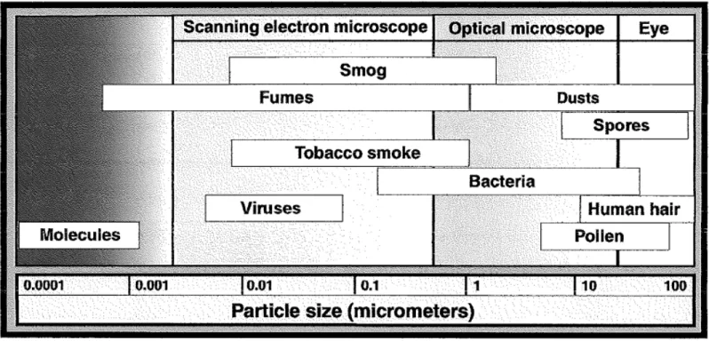
Particulates found in indoor environments cover a wide range to types and size ranges (Figure 2 provides a simple overview). According to Health Canada’s Guidelines for Residential IAQ, size of particles may range from 0.005 µm to 100 µm in diameter. The size range of concern when human health effects and indoor air quality are considered is from 0.01 µm to 10 µm in aerodynamic diameter. PM10 are particles that are 10 µm or less in aerodynamic diameter; coarse particles are those with aerodynamic diameters between 2.5 and 10 µm. Above 15 µm, most particles are too large to be inhaled. PM2.5 are particles of 2.5 µm or less in diameter. For fine particulate matter (≤2.5 µm mass median aerodynamic diameter), HC sets an Acceptable Long-Term Exposure Range (ALTER) for residential indoor air of ≤40 µg/m3. Allergenic materials such as spores, pollen, and cat dander are typically larger than 2.5µm, thus the PAC impact on both fine and “coarse” particle fractions should be considered. The finer particles pose a threat to human health because they can travel deepest into the lungs.
Figure 2 Common particulate air contaminants and their relative sizes (source: Hinds, 1982)
Ultrafine particles (UFPs) which have an aerodynamic diameter of <0.1 µm, are potentially the most dangerous owing to their small size, large surface area/volume ratio, high content of redox cycling organic chemicals, deep penetration, and high rates of retention in the lung (Nel, 2005). There are no standards/guidelines on ultra-fine particles at the moment in Canada for residential settings. However, scientific discussions are ongoing on the formation of a standard. Nevertheless, Table 2 provides some reference concentrations.
Page | 15 Table 2 Reference ultrafine particle (UFP) concentrations
Environment UFP Concentration (no/cm3)
Unoccupied homes 2000-12000
Occupied homes 2000-80000
Office air 2000 – 4000
Ambient air in urban area 10000 – 30000 Polluted outside air > 50000
Wallace, 2009; Bhangar et al., 2011
No single analytical method can span the full range of particulates found indoors, thus characterization of PAC performance with regards to particulate removal (or unintended generation) will require the use of several classes of analytical instruments. Similarly, more than one class of particle generation device may be needed to provide the particle challenge atmospheres necessary to fully test PAC performance.
3.3.1 Particle Generation
The particle generator shall provide stable test particles of sufficient concentration over the 0.05 to 5 µm diameter size range to meet the requirements of Section 5 without overloading the aerosol particle counter.1 The test particles shall be polydisperse potassium chloride (KCl) or sodium chloride (NaCl) particles generated from an aqueous solution. Polydisperse liquid particles are usually produced by nebulizing the particle substance through a binary nozzle using compressed air. A drying process is then required prior to introduction of the particulates into the test chamber. Since electrically charged particles are removed more effectively by filters than are uncharged particles, the particles should be electrically neutral to fairly assess PAC performance. Thus the dried particles shall be brought to a Boltzman electrostatic charge distribution by a beta or gamma radiation generator with an activity of at least 185 MBq (5 mCi) or a corona discharge ionizer. The corona discharge ionizer shall have a minimum corona current of 3 µA and shall be balanced to provide equal amounts of positive and negative ions.
3.3.2 Particle Measurement
The particle measuring systems shall be capable of counting and sizing individual KCl / NaCl particles in the 0.05 to 5 µm diameter size range. Since the test particles straddle the range from ultrafine (<0.1µm) to fine particles (0.1 to 2.5 µm) to coarse particles (above 2.5 µm), no single instrument will be capable of measuring the complete particle spectrum. Both size-specific and total particle concentrations in two size groups are to
1
Ideally, the performance of the PAC in particle removal should be evaluated over the entire range of health-relevant particle sizes expected to be present during its intended use. This range would encompass particles from approximately 0.01 to 10 microns. Preliminary measurements showed however, there are technical problems in generating and/or measuring particles below 0.05 microns and above 5 microns.
be acquired. The two particle size groups are the: 1) ultrafine particle group and 2) fine and coarse particle group.
Typically, total ultrafine particle concentration can be measured using a condensation particle counter (CPC). CPC could come in the form of bench-top as well as portable units. Classifying ultrafine particles is normally conducted using a differential mobility analyser (DMA) which is based on electrical mobility of particles. The electrical mobility of a particle is a function of the particle size and the number of charges the particle has. A CPC which enlarges small particles by condensation of a vapour before being subjected to light scattering measurements is used in conjunction with the DMA. Alternatively, ultrafine particles can be measured using equipment based on charging the particles system and multiple electrometers to get signals from all particle sizes simultaneously.
For fine and coarse particles, optical particle counters (OPC) which determines particle size based on the intensity of the particle's scattered light can be used. A better alternative is the use of aerodynamic particle sizer (APS) which determines particle size by measuring the time of flight of the particle. Typically, OPCs would demonstrate good correlation in measuring particle size concentrations with an APS. It is highly recommended that an APS shall first be tested with KCl/NaCl to establish the relationship between the aerodynamic particle size and the light-scattering particle size determined by an OPC.
3.4 Test Apparatus for VOCs 3.4.1 VOC Generation
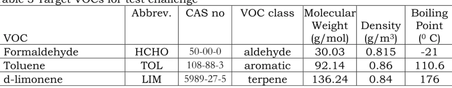
The target VOCs used for the protocol include formaldehyde, toluene and d-limonene (Table 3). These target VOCs are typically encountered in Canadian indoor environments (Otson et al, 1994; Gilbert et al., 2005; 2006). They represent organic compounds from various VOC classes. In residences, they represent the various sources of VOCs– formaldehyde is known to be from wood-based products; toluene is reported to be from solvents and gasoline; and d-limonene is from cleaning products and air fresheners. Methods for generation of VOCs mixtures can be in the form of syringe injection systems, compressed gas cylinders containing mixtures at levels suitable for delivery via precision flow control systems, permeation tubes, bubbler/impinger or liquid vaporization systems. The generation of gaseous VOCs from liquid standards has to consider the various volatility characteristics. Unvaporized aerosol particles might underestimate the VOC filtration performance. The test method recommends that the challenge liquid VOCs be vaporized into a carrier gas. Safety and health aspects must be considered taking into account irritancy and toxicity of individual challenge VOCs as well as their explosive and flammable limits during vaporization.
For VOCs generation, clean air is to be supplied where the content of individual target VOCs in the influent air shall not exceed 1.0 ppm and shall not exceed 0.2% of the
challenge concentration for each VOC tested. The VOC generator shall be designed to ensure that the VOC challenge can attain the target concentrations within a nominal ± 5%.
Table 3 Target VOCs for test challenge
VOC
Abbrev. CAS no VOC class Molecular Weight (g/mol) Density (g/m3) Boiling Point (0 C)
Formaldehyde HCHO 50-00-0 aldehyde 30.03 0.815 -21
Toluene TOL 108-88-3 aromatic 92.14 0.86 110.6
d-limonene LIM 5989-27-5 terpene 136.24 0.84 176
3.4.2 VOC Measurement
As with particulate contaminants, a wide range of gaseous or volatile pollutants exist in indoor environments. These include compounds with extremely high volatility (such as formaldehyde) to much heavier compounds that are classified as being semi-volatile. Add to this the variable chemical nature of these compounds (for example in terms of polarity), and it can be seen that accurate measurement and generation of gas-phase PAC challenges will also require more than one device.
3.4.2.1 VOC Sampling
For VOCs sampling, chamber transport through PTFE and 316 stainless steel sample lines is advocated. Sampling line lengths should be kept to a minimum to limit adsorptive losses. The airflow rate of sampling systems shall be as low as possible consistent with the transport requirements of the chamber supply airflow rate. A compromise must therefore be reached between minimizing sample lag times while also controlling impact on chamber ventilation conditions.
For VOC sampling, two collection cartridge types are used: 1) 2-4 dinitrophenyl hydrazine (DNPH) to collect formaldehyde; and 2) Tenax tubes are used to collect toluene and d-limonene. The volume through the sample cartridges should range from 10 mL to 10 L depending on the concentration of the VOCs in test chamber. Samples should be taken after injection at stated levels at 0 min, 5 min, 10 min, 15 min, 20 min, 25 min, 30min, 45 min, 1 hr, 1.5 hr, 2 hr, 3 hr and 4 hr during VOC removal performance testing. Duplicate samples should be taken. Sampling rate should not be higher than 200 mL/min.
3.4.2.2 VOC Analysis
For VOC analysis, the quantitative analysis of the target compounds cannot be achieved by applying a single technique. Two analytical methods were selected in this study: 1) Gas Chromatograph – Mass Spectrometer (GCMS) technique; and 2) High Performance Liquid Chromatograph (HPLC) technique.
In the GCMS, principal methodology is to use a thermal desorption system for elution of collected toluene and d-limonene into a GC where they are separated using a non-polar capillary column and quantified using a mass spectrometer. Extracted ion rather than total ion technique using individual response factors for mass calculations is preferred due to the method’s enhanced precision and accuracy.
For formaldehyde analysis, ASTM D 5197-03 Test Method for “Determination of Formaldehyde and Other Carbonyl Compounds in Air (Active Sampler Methodology)” (ASTM, 2003) should be followed. This involves the elution of collected cartridges with acetonitrile under gravity feed and analysis by the HPLC system equipped with Zorbax ODS (or equivalent) column and UV-VIS detector using acetonitrile in water as a mobile phase for separation of compounds. Alternatively EPA Method TO-11A (EPA, 1999c) may be employed.
3.5 Test Apparatus for Acoustic Measurements
The instrumentation used for the acoustical measurements of the ILG reference sound source and each test source should include: a microphone, microphone preamp, microphone power supply and a calibrator. The calibrator should be calibrated annually.
3.6 Test Environment Monitoring and Data Acquisition System for IAQ Performance
3.6.1 Temperature
The air temperature measuring instruments should be able to measure between the ranges of 15 to 35°C with an accuracy of ±0.1°C. This accuracy shall be guaranteed for a difference between air temperature and mean radiant temperature equal to or less than 10°C. During measurements, precautionary steps to protect the sensor from any influence of thermal radiation from neighbouring heat sources, e.g analyzers, PAC devices, contaminant generators, should be taken. Response time for the instrument should be the shortest response time possible (1 sec maximum). The resolution of the instrument should be at least 0.1 °C.
3.6.2 Relative Humidity
There are many instruments available for measuring the relative humidity of air. This includes psychrometers, chilled mirror and hygrometers. The air relative humidity measuring instruments should be able to measure between the ranges of 0 to 100 % with an accuracy of ±1 %. The resolution of the instrument should be 0.1 %. Response time for the instrument should be the shortest response time possible (1 minute minimum).
3.6.3 Air Velocity
The test chamber air motion shall be determined by air velocity measurements. An omni-directional anemometer shall be used to measure the air velocity. Directionally-sensitive anemometers may be used as an alternative if carefully oriented to indicate the true air speed at any test position. This may require a smoke test to determine the primary flow direction. Examples of instruments measuring air velocity include hot-wire anemometer, hot-sphere and thermistor anemometer, ultrasonic anemometer, and laser-doppler anemometer. The instrument should be able to measure air velocity within the range of 0.1 to 5 m/s at an accuracy of ±0.05 m/s or ±5% of reading, whichever is greater. The resolution of the instrument should be at least 0.01 m/s. The response time of the instrument should be 0.2 seconds minimum.
3.6.4 Ozone
Health Canada’s proposed residential indoor air quality guideline for ozone has been set at 20 ppb (40 µg/m3) for 8 h exposure. Ozone levels in the chamber air shall be determined using an analyzer based on either chemiluminesence or UV absorption at 254 nm. The range of measurements for the instrument shall be from 1.5 ppb to 100 ppm with accuracy of 1.5 ppb or 2% of reading and resolution of 0.1 ppb. The response time of the equipment should be at most 1 minute.
3.6.5 Chamber Mixing
The test chamber shall have proper mixing verified via the mixing procedure of the standard practice for full scale chamber determination of volatile organic compounds emissions from indoor materials/products, ASTM D6670, Sections titled Air Distribution in the Chamber and Air-Mixing in a Chamber or ASHRAE Standard 129 test method (ASHRAE, 1997). A mixing level of higher than 80% may be considered satisfactory. The test chamber shall not create local airflow across the surface of the product under test exceeding 0.1 m/s.
3.6.6 Air Exchange Rate
Chamber air exchange rate measurements shall be determined using concentration decay of tracer gas techniques. Sulphur hexafluoride is recommended as a tracer gas although other gases (e.g. perfluorohydrocarbons ) can be considered if they do not reduce collection efficiencies and increase sample breakthrough of the VOC adsorption tubes. The procedure, similar to ASTM E 471-00 Test Method for “Determining Air Change in a Single Zone by Means of a Tracer Gas Dilution” (ASTM, 2006) is recommended for chamber air exchange rate analysis.
3.6.7 Data Acquisition System
Remote monitoring of indoor parameters using a data acquisition system (DAS) is highly recommended. The DAS should comprise of a microcomputer/DAS software, interface boards/multiplexor plus sensors/power supplies/cables for measuring airflow rates,
temperatures, relative humidities, air velocities, pressures, concentrations at selected locations in the test chamber and in the HVAC ducts. The DAS should be able to remotely turn on or off the portable air cleaner without person entry into the chamber.
4 Background Conditions for IAQ Performance 4.1 System Qualification and Calibration
The purpose of the system qualification and calibration tests is to verify the accurate measurements of the PAC performance can be made in the test facility. The qualification tests include checks on the following measurements:
• Volumetric airflow rates, chamber pressure differential, temperature and humidity
• Background particle count number concentrations and upper concentration limit for particle analyzers
• Background VOC and ozone concentrations
• Chamber mixing – uniformity of particle, VOC and ozone challenge
• Minimum VOC sink effects on chamber walls
• System response time
• Calibration of instruments should be performed as per manufacturer’s recommendation
4.2 Conditions for Measurement
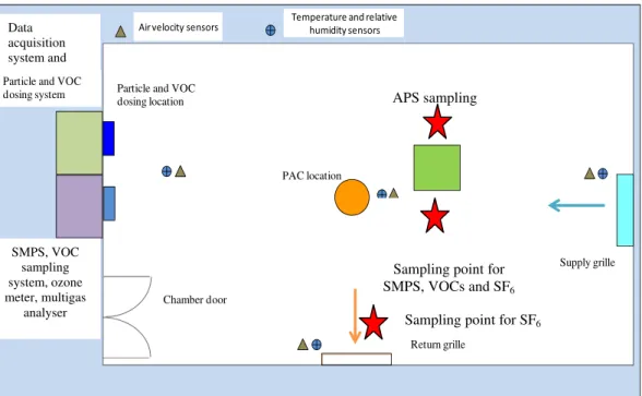
For performance assessment related to IAQ, all the measurements shall be conducted in the test chamber illustrated in Figure 3 under the following conditions:
• Portable air cleaner sitting on floor in the middle of the test chamber
• Test chamber temperature is to be 21.0 ± 2 0C with relative humidity (RH) of 40 ± 5 %
• Test chamber air exchange rate is to be less than 0.05 ACH with chamber mixing more than 80%.
• Supply air grill to the chamber should be upward facing while the return air grill should be sideward facing towards the middle of the chamber.
• Sampling locations for temperature, relative humidity and air velocity at the supply and return grills, and the middle and corner of the chamber as given in Figure 3.
• Particle measurements and individual VOC sampling will be conducted in the middle of the chamber.
• Particle and VOC dosing locations will be from the wall at the side of the chamber at a height of at least 1 meter above the floor.
• Test chamber particle concentrations o Maximum background concentration:
50 particles/cm3 (total SMPS) 5 particles/cm3 (total APS)
Page | 21 o Minimum concentration range after injection:
1000 no/cm3 (for all size bins measured using SMPS) 10000 no/cm3 (for total SMPS)
20 no/cm3 (for all size bins measured using APS) 200 no/cm3 (for total APS)
• Test chamber VOC concentrations
o Maximum background concentration: 10 μg/m3 (for all test VOCs)
o Minimum concentration range after injection:
800 μg/m3 (for toluene and d-limonene) 200 μg/m3 (for formaldehyde)
• Test chamber ozone concentrations
o Maximum background concentration: 5 ppb
• Conditioned VOC sorbent tube shall not exceed 50% of target VOCs mass collected during the background concentration
Figure 3. Schematic layout of the test chamber assessing IAQ performance of the portable air cleaner
PAC location
Supply grille
Return grille Particle and VOC
dosing location particle measuring instruments VOC sampling location on-line TVOC analyser Chamber door Data acquisition system Particle and VOC dosing system
Air velocity sensors Temperature and relative humidity sensors
APS sampling
Sampling point for SMPS, VOCs and SF6
Sampling point for SF6 SMPS, VOC sampling system, ozone meter, multigas analyser Data acquisition system and
5 Test Procedure for Determining Performance 5.1 IAQ Performance Test
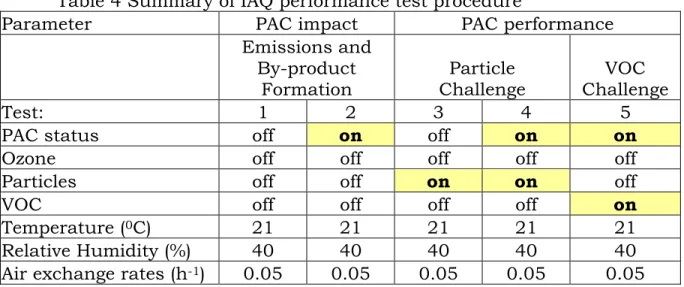
The IAQ performance test is summarised in Table 4. After the device and test chamber have been prepared (see Section 4), the sequence of performance tests on each device shall be as follows:
Table 4 Summary of IAQ performance test procedure
Parameter PAC impact PAC performance
Emissions and By-product Formation Particle Challenge VOC Challenge Test: 1 2 3 4 5
PAC status off on off on on
Ozone off off off off off
Particles off off on on off
VOC off off off off on
Temperature (0C) 21 21 21 21 21
Relative Humidity (%) 40 40 40 40 40
Air exchange rates (h-1) 0.05 0.05 0.05 0.05 0.05
5.1.1 Portable Air Cleaner Emissions and By-product Formation
The VOC, ozone and ultra-fine particle emissions of the portable air cleaner under working and non-working conditions within the chamber is evaluated (Test 1 and 2).
5.1.1.1 Emission Measurements with PAC turned off
The following test is intended to check for the possibility that the PAC may itself be a source of IAQ contaminants (VOCs, ozone, and ultrafine particles).
5.1.1.1.1
Establish the environmental and chamber conditions in accordance with Section 4. 5.1.1.1.2
The air cleaner is placed in the chamber, tested for proper operation and then switched off.
5.1.1.1.3
Perform VOC sampling and analysis to determine concentrations for the 3 VOCs under steady state conditions. Steady state concentrations for each of the target VOCs shall not exceed 10 μg/m3.
5.1.1.1.4
Perform particle measurements to determine steady state concentrations. Concentrations should not exceed 50 no/cm3 for total ultrafine particles and 5 no/ cm3 for total fine and coarse particles under steady state conditions.
5.1.1.1.5
Perform ozone measurements to determine background steady state concentration. Background ozone concentrations shall not exceed 5ppb under steady state conditions.
5.1.1.1.6
Net emission rates of ozone, VOCs and total ultrafine particles are calculated as per Section 7.1.
5.1.1.2 Emission Measurements with PAC turned on 5.1.1.2.1
Establish the environmental and chamber conditions in accordance with Section 4. 5.1.1.2.2
The air cleaner is switched on at maximum setting (if PAC incorporates multiple technologies, then all available systems should be operated at maximum mode according to manufacturer’s instructions).
5.1.1.2.3
Perform VOC measurements to determine steady state concentrations for the target VOCs under steady state conditions.
5.1.1.2.4
Perform particulate measurements determine steady state concentrations for total ultrafine particles.
5.1.1.2.5
Net emission rates of VOCs and total ultrafine particles are calculated as per Section 7.1.
5.1.1.2.5.1
Compare the calculated formaldehyde net emission rate of the device with the expected ‘standard’ emission rate which will give a steady state formaldehyde concentration of 40 ppb as per Section 7.1. Rate the formaldehyde emission as per Section 7.1
5.1.1.2.5.2
Compare the calculated net particles (total ultrafine particles) emission rate of the device with the background levels as per Section 7.1. Rate the particle emission as per Section 7.1
5.1.1.2.6
Perform ozone emissions measurements. 5.1.1.2.6.1
Measure the background (outside of the chamber) ozone concentrations as per Section 3.4.4 for 5 minutes
5.1.1.2.6.2
Measure the ozone concentrations for 24 hours. The equilibrium ozone concentration which is defined by the average of all 30 minute background corrected steady state concentration is computed.
For devices where ozone concentration did not increase under steady state conditions, the test is to be terminated.
5.1.1.2.6.3
After 24 hours, turn off the PAC and continue to monitor the ozone concentration. Ozone concentration acquisition should be at least 30 minutes where a minimum of 9 valid ozone data points is required for the analysis
5.1.1.2.6.4
The first order decay constant and net emission rate are calculated for ozone as per Sections 6.6 and 7.1.
5.1.1.2.6.5
Compare the calculated net emission rate of the device with the expected ‘standard’ emission rate which will give a steady state ozone concentration of 20 ppb as per Section 7.1. Rate the ozone emission as per Section 7.1
5.1.2 Portable Air Cleaner Particle and VOC Removal
This section relates to the evaluation of portable air cleaner performance under particle (Tests 3-4) and VOC (Test 5).
5.1.2.1 Particle Challenge
The particle challenge test includes two sets of measurements: 1) natural decay measurements and 2) particle removal with natural decay measurements (Tests 3-4).
5.1.2.1.1 Particle Removal with Natural Decay Measurements 5.1.2.1.1.1
The air cleaner is placed in the chamber, tested for proper operation and then switched off.
5.1.2.1.1.2
Establish the environmental and chamber conditions in accordance with Section 4. 5.1.2.1.1.3
Prepare 2.9E-03 mol/m3 NaCl solution to be added to the container of 6-jet atomizer. The pressures and airflows to the nozzle of the atomizer should be adjusted accordingly to achieve minimum concentration specified in Section 4.2. The initial concentration of the total ultrafine particle should reach a minimum 10000 particles/cm3 while initial concentration of the total fine and coarse particles should reach 200 particles/cm3. The corresponding initial concentration for all size bins for ultrafine particles and fine and coarse particles should reach a minimum 1000 and 20 particles/cm3 respectively. After the minimum concentrations have been attained, the particle challenge is stopped and the generator is shut down. 5.1.2.1.1.4
After 3 minutes, acquisition of particle concentrations begins and the initial concentration at time (t=0) is recorded.
5.1.2.1.1.5
Particle concentration acquisition should be at least 30 minutes at a maximum of 3 minute sampling intervals. A minimum of 9 particle data points is required for the analysis.
5.1.2.1.1.6
The first order decay constant is calculated for particle size bins as per Section 6.1. 5.1.2.1.1.7
The acceptability of the challenge test is calculated using the correlation coefficient and standard deviation of the first order decay constant as per Sections 6.2 and 6.3. A minimum correlation coefficient of 0.95 and 0.90 for total and size resolved particles respectively determines if the test is acceptable.
5.1.2.1.2 Particle Removal with Natural Decay Measurements 5.1.2.1.2.1
Establish the environmental and chamber conditions in accordance with Section 4.
5.1.2.1.2.2
Prepare 2.9E-03 mol/m3 NaCl solution to be added to the container of 6-jet atomizer. The pressures and airflows to the nozzle of the atomizer should be adjusted accordingly to achieve minimum concentration specified in Section 4.2. The initial concentration of the total ultrafine particle should reach a minimum 10000 particles/cm3 while initial concentration of the total fine and coarse particles should reach 200 particles/cm3. The corresponding initial concentration for all size bins for ultrafine particles and fine and coarse particles should reach a minimum 1000 and 20 particles/cm3 respectively. After the minimum concentrations have been attained, the particle challenge is stopped and the generator is shut down. 5.1.2.1.2.3
The air cleaner is turned on in the chamber. The time at which the air cleaner is turned on is recorded as t=0.
5.1.2.1.2.4
After 2 minutes of turning on the air cleaner, acquisition of particle concentrations begins and the initial concentration is recorded.
5.1.2.1.2.5
Particle concentration acquisition should be at least 30 minutes at a maximum of 3 minute sampling intervals. A minimum of 9 particle data points is required for the analysis.
5.1.2.1.2.6
The first order decay constant is calculated for particle size bins as per Section 6.1 5.1.2.1.2.7
The acceptability of the challenge test is calculated using the correlation coefficient and standard deviation of the first order decay constant as per Sections 6.2 and 6.3. A minimum correlation coefficient of 0.95 and 0.90 for total and size resolved particles respectively determines if the test is acceptable.
5.1.2.1.3 Portable Air Cleaner Performance 5.1.2.1.3.1
Determine the CADR of the portable air cleaner as per Section 6.4 5.1.2.1.3.2
Determine the acceptability of the test CADR of the portable air cleaner as per Section 6.5. A standard deviation less than CADR = 39 m3/hr or 20%, whichever is greater, determines if the test is acceptable.
5.1.2.2 VOC Challenge
The VOC challenge test involves the VOC removal with natural decay measurements (Test 5). As the sink effects of VOCs on the stainless steel chamber is insignificant, it is to be ignored from the calculation of the natural decay constant. The VOC natural decay constant, kn,V (h−1), due to air exchange is to be obtained from the air exchange rates measurements.
Some portable air cleaner technologies may possess non-linear decay characteristics (Chen et al., 2005). This may make the direct fitting of all experimental data to in step 5.1.2.2.1.7 inappropriate. An alternative data regression fit is to be used (see section 5.1.2.2.1.7).
5.1.2.2.1 VOC Removal with Natural Decay Measurements 5.1.2.2.1.1
Establish the environmental and chamber conditions in accordance with Section 4. 5.1.2.2.1.2
Prepare the VOC solutions and load them in the syringe pump. The syringe pumps are used to introduce VOCs into the chamber. The initial concentration of the target VOCs should reach the minimum concentration levels stipulated in Section 4.2. After the concentration levels have been attained, the VOC challenge is stopped and the syringe pumps are shut down.
5.1.2.2.1.3
The air cleaner is turned on in the chamber after one minute the dosing has stopped. The time at which the air cleaner is turned on is recorded as t=0. 5.1.2.2.1.4
After 5 minutes of turning on the air cleaner, acquisition of VOC concentrations begins and the initial concentration is recorded.
5.1.2.2.1.5
For target VOC measurements, sampling may be performed at time = 5 min, 10 min, 15 min, 20 min, 25 min, 30min, 45 min, 1 hr, 1.5 hr, 2 hr, 3 hr and 4 hr. Sampling flow rate shall be at 200 ml/min. A minimum of 9 data points (including those at time = 5 min and 4 hr) is required for the analysis.
5.1.2.2.1.6
The first order decay constant is calculated for VOCs as per Section 6.1.
5.1.2.2.1.7
The correlation coefficient and standard deviation of the first order decay constant as per Sections 6.2 and 6.3 shall be computed and reported. A minimum correlation coefficient of 0.9 determines if the test is acceptable.
If the data cannot fit the measured concentration decay curve well (i.e. regression coefficient R2 < 0.85), regress the concentration versus time with a double exponential decay format. A minimum correlation coefficient of 0.9 determines if the test is acceptable.
5.1.2.2.2 Portable Air Cleaner Performance 5.1.2.2.2.1
Determine the CADR of the portable air cleaner for the target VOCs as per Section 6.4
5.1.2.2.2.2
Determine the acceptability of the test CADR of the portable air cleaner as per Section 6.5.
5.1.2.2.2.3
Determine the SPE of the portable air cleaner for the target VOCs as per Section 7.2.2.
5.2 Sound Power Level Measurements
The maximum output sound power level of each portable air cleaner is measured following the procedure of ISO 3743-1 to provide ‘engineering’ grade measurements of the sound power levels. ISO 3743-1 is a comparison procedure which compares the measured sound pressure levels of a test source such as a PAC with the levels measured for a calibrated reference sound source at the same positions in a reverberant test room. The sound power output of the reference sound source, such as the ILG source, must first be measured to a ‘precision’ grade using the ISO 3741 procedure. The reference sound source must also comply with the requirements in ISO 6926 for reference sound sources.
5.2.1
As specified in ISO 3743-1 the portable air cleaner should be placed on the floor of the reverberation chamber at least 1 m from all walls.
5.2.2
While the sound levels of the portable air cleaner are measured, it should be operating at its maximum setting with all additional features switched on.
5.2.3
Measure the sound pressure levels of the portable air cleaner in accordance with the ISO 3741-3 standard. Following this standard calculate sound power levels by comparison with the measured sound pressure levels of the reference sound source at the same measurement locations and using the previously determined sound power levels of the reference sound source.
5.3 Electrical Power Measurements
5.3.1 Electrical Operating Power Measurements 5.3.1.1
Connect the electrical power measuring equipment between the power supply and the air cleaner.
5.3.1.2
Turn on the air cleaner at maximum setting, reset power measuring equipment and adjust the power supply indicator to 120 Volts – 60 Hertz
5.3.1.3
Leave the air cleaner to stabilize for 5 minutes. Record the watt readings for 10 minutes at one-minute intervals. The operating power result is obtained by averaging the 10 readings.
5.3.2 Electrical Standby Power Measurements 5.3.2.1
Connect the electrical power measuring equipment between the power supply and the air cleaner in the standby mode.
5.3.2.2
Leave the air cleaner to stabilize for 5 minutes. Record the watt readings for 10 minutes at one-minute intervals. The standby power result is obtained by averaging the 10 readings.
5.4 Air Flow Rate Measurements
The velocities and cross section area at the supply air outlet of the PAC shall be measured. A hotwire anemometer velocity meter shall be used to measure air velocities at multiple points on the supply outlet of the PAC. Measurements are to be computed according to the following procedure:
5.4.1
Measure the dimensions (e.g. length and width) of supply air outlet of the PAC and determine the cross-section area.
5.4.2
Determine the measuring points on the cross-sectional area of the supply air outlet. The measuring points along the plane of the outlet shall be made at the intersection of imaginary lines that will cross the outlet vertically and horizontally. At least
twenty-five points shall be considered. 5.4.3
Turn on the air cleaner at maximum setting, with all additional features switched on.
5.4.4
Take measurement at each measuring points, record reading and then move the velocity probe to the next measuring point.
5.4.5
Determine the average value of the velocity measurements from the twenty-five measuring points
5.4.6
Determine the product of cross-section area and the average velocity to obtain the PAC air flow rate.
6 Calculation Procedures
6.1 Calculating the First Order Decay Constant
Equation X1 described the first order decay constant, k, for contaminant:
kt
e
o
C
t
C
=
−
(X1)Where Ct is the contaminant concentration at time t (no/m3 or mg/m3)
C0 is the initial contaminant concentration at time 0 (no/m3 or mg/m3)
k is the first order decay constant (1/h) t is the time (h)
Taking the natural log of both sides and rearranging equation X1 gives
∑ ⎟⎟ ⎠ ⎞ ⎜ ⎜ ⎝ ⎛ ∑ ⎟ ⎟ ⎠ ⎞ ⎜ ⎜ ⎝ ⎛ ∑ ⎟ ⎟ ⎠ ⎞ ⎜ ⎜ ⎝ ⎛ ∑ ⎟ ⎟ ⎠ ⎞ ⎜ ⎜ ⎝ ⎛ ∑
−
−
=
n
n
i
t
n
i
t
n
i
t
C
n
i
t
n
n
i
t
C
i
t
k
1
2
1
1
2
1
ln
1
1
1
ln
(X2)Where
t
i
is the time at i (h)ln is the natural logarithm of the contaminant concentration at time
i
t
C
t
i
n is the number of pair of measurements
Concentration of particles and VOCs measured sequentially during the decay period are statistically fit to the log form of model equation using linear regression. The first order decay constant is obtained from the slope of the fit.
6.2 Calculating the Correlation Coefficient
The measure of linear association between the time and natural logarithm of the
contaminant concentration is estimated by the correlation coefficient r given in equation X3 ⎟ ⎟ ⎠ ⎞ ⎜ ⎜ ⎝ ⎛ ∑ ⎟ ⎟ ⎠ ⎞ ⎜ ⎜ ⎝ ⎛ ∑ ⎟ ⎟ ⎠ ⎞ ⎜ ⎜ ⎝ ⎛ ∑