Publisher’s version / Version de l'éditeur:
Vous avez des questions? Nous pouvons vous aider. Pour communiquer directement avec un auteur, consultez la
première page de la revue dans laquelle son article a été publié afin de trouver ses coordonnées. Si vous n’arrivez pas à les repérer, communiquez avec nous à [email protected].
Questions? Contact the NRC Publications Archive team at
[email protected]. If you wish to email the authors directly, please see the first page of the publication for their contact information.
https://publications-cnrc.canada.ca/fra/droits
L’accès à ce site Web et l’utilisation de son contenu sont assujettis aux conditions présentées dans le site LISEZ CES CONDITIONS ATTENTIVEMENT AVANT D’UTILISER CE SITE WEB.
Annual Technical Conference ANTEC 2006 (SPE) [Proceedings], 2006-05-07
READ THESE TERMS AND CONDITIONS CAREFULLY BEFORE USING THIS WEBSITE. https://nrc-publications.canada.ca/eng/copyright
NRC Publications Archive Record / Notice des Archives des publications du CNRC :
https://nrc-publications.canada.ca/eng/view/object/?id=3424c32f-754f-4d62-bfec-b06a86f1e230
https://publications-cnrc.canada.ca/fra/voir/objet/?id=3424c32f-754f-4d62-bfec-b06a86f1e230
NRC Publications Archive
Archives des publications du CNRC
This publication could be one of several versions: author’s original, accepted manuscript or the publisher’s version. / La version de cette publication peut être l’une des suivantes : la version prépublication de l’auteur, la version acceptée du manuscrit ou la version de l’éditeur.
Access and use of this website and the material on it are subject to the Terms and Conditions set forth at
Polymer nanocomposites fibers and applications
Ajji, Abdellah; Denault, Johanne; Bureau, Martin; Ton-That, Minh-Tan;
Trudel-Boucher, David; Côté, Daniel
POLYMER NANOCOMPOSITES FIBERS AND APPLICATIONS
Abdellah Ajji
1, Johanne Denault
1, Martin Bureau
1, Minh-Tan Ton-That
1,
David Trudel-Boucher
1and Daniel Côté
21
Industrials Materials Institute, National Research Council of Canada
2
Mechanical Engineering Department, McGill University
Abstract
Different polymer nanocomposite (polypropylene-clay and polyethylene terephthalate-hydroxyapatite) fibers were produced by melt blowing. Fibers exhibit interesting mechanical properties attributed to polymer and nanoparticle orientation. Fibers could be organized and consolidated into 3D structures with retained improved mechanical properties. Structural and biomedical of these structures are presented.
Introduction
Polymer nanocomposites (PNCs) based on nano-layered silicates have attracted much attention during the past ten years because of their low cost, their ready availability, and their non-isometric structure derived from a high aspect ratio, which can maximize the reinforcing effect in terms of mechanical, thermal, and barrier properties (1). PNCs also present an extraordinary opportunity for polymers to be used in tissue repair and reconstruction (TRR) applications, in light of their improved structural (mechanical, thermal, etc.) and functional properties (electric, magnetic, biologic, etc.). Indeed, bone tissue for example is a hierarchically structured composite material (2) formed of nanofibers containing a polymer phase, collagen type I, and a mineral phase, crystalline apatite nanoparticles, organized in a complex 3D structure (porous or dense, anisotropic or isotropic). Inspired by original work on carbon nanotubes/polymer spun fibers (3,4), fiber-based structures for biomedical applications have been proposed, mainly based however on bone-like ceramic nanoparticles and bioresorbable polymers, but very few if any focused on load-bearing, permanent TRR implants.
In comparison with the pure polymer or conventional (microscale) composites, the presence of nano-layered silicates in the polymer matrix can significantly increase moduli, strength, and heat resistance, and decrease gas permeability and flammability. However, good dispersion of nanoclay in the polymer matrix and a good interface between the two phases are essential to achieve the improvements mentioned. In addition, mechanical properties as in conventional polymer is dependent upon nanoparticles orientation. One of the best method to achieve good orientation of nanoparticles and to control this orientation is to try to align the nanoparticles in polymer fibers.
Two reinforcing effects can be targeted by using polymer fibers reinforced with nanoparticles of nano clay when use to develop a microcomposite structure . First, the presence of nanoparticles will increase the mechanical properties of the polymer fibers and this effect is related to the alignment of those nanoparticles during the drawing process. Secondly, if we carefully select the consolidation temperature of those fibers, we might be able to keep the orientation of the polymer chain in the final micro composite. The objective of this work was to validate the potential of nanoparticles to reinforce polymer fibers and to test them as a precursor for the fabrication of a microcomposites. It was also to develop bioactive polymer-apatite nanocomposite fibers and evaluate their bioperformance potential, in terms of biocompatibility. These fibers will eventually be used to build complex 3D structures, either porous or dense structures, with bioresorbable and/or permanent functions, for selected TRR applications.
Experimental
The polymer used was a polypropylene (PP1274) having an MFR of 12 and density of 0.902 obtained from Basell Company. A PNC based on the same PP (designated PPNC) was produced using a twin-screw extruder from a masterbatch containing 10wt% of Cloisite 15A from Southern clay with 10wt% of maleic anhydride grafted PP, EP3015 of Eastman Chemical. Masterbatch was then diluted to 2wt% clay with the extruder.
Polyethylene terephthalate (PET, Traytuf 8506 having an IV of 0.85 obtained from M&G company) compounded with hydroxyapatite (HA, Plasma Biotal, Captal 30) particles (d50of 30 µm) was also used to produce fibers. A
masterbatch was first compounded 240°C with a nominal HA content of 40wt%, then diluted to concentration of 2, 4, 6, 8 and 10wt% HA.
To produce the fibers, both PP and PPNC fibers were extruded through a 1.25’’ extruder, followed by a gear pump and fiber die. The die contained 150 holes having a diameter of 380µm and spaced by 0.5 mm. The polymer temperature was fixed at 220°C and flow rate of 4.0 kg/hr. The draw down speed was varied to achieve various draw ratios in air. PET and PET/HA fibers were produced in the same conditions except for temperature, set at 280°C.
The structure of PP and PPNC fibers as was evaluated using field emission scanning electron microscopy (FE-SEM) and X-ray diffraction. The crystalline axes orientation
factors were determined from wide-angle X-ray diffraction pole figures of (110) and (200) reflections using a Bruker AXS X-rays goniometer equipped with a Hi-STAR two-dimensional area detector. The generator was set up at 40kV and 40mA and the copper K radiation ( =1.542 Å) was selected using a graphite crystal monochromator. Sample to detector distance was fixed at 8 cm. Fiber samples were stacked to a thickness of about 2 mm in order to obtain enough accuracy in a reasonable time. The d-spacing of the (001) clay crystalline plane, indicative of the clay dispersion, was determined from the theta-2*theta plots superimposed on the two dimensional X-ray diagrams. Similar characterization was also done on PET/HA fibers.
Individual PP and PPNC fibers were then tested in tension at 23°C using a 10 N load cell at a crosshead speed of 120 mm/min according to ASTM D3822. Small pneumatic clamps were used to grip individual fibers. Fiber gage length was 50 mm. Tensile modulus, tensile strength and elongation at break was obtained from the load-deflection curves. Twenty specimens were tested per fiber condition.
Unidirectional laminates were then produced to determine the mechanical properties of micro composites manufactured from PPNC fibers. These laminates were manufactured by rolling the continuous strands of fibers around an aluminum plate connected to a variable speed electric motor to ensure that fibers are parallel. They were then inserted in an aluminum mold (152 x 152 mm2) and
consolidated into 3-mm thick laminates using a heated press. This procedure allowed the production two laminates at the same time. The platen temperature was fixed to 170°C. Heating was stopped when laminate temperature reached 165°C and cooled to 60°C in 4 min. Maximum temperature reached was 166.5°C.
Flexural tests were performed on these laminates at 23°C using a three point bending set-up according to ASTM D790. These tests were performed at a crosshead speed of 1.3 mm/min using a span-to-depth ratio of 16. Specimens (12.5 mm wide) were cut from the laminates in the longitudinal and transverse direction, referred to as LD and TD. Flexural modulus and flexural strength in the outer fibers of the composites were then obtained from the load-displacement curves. Five specimens were tested for each testing direction. Optical micrographs of polished cross-sections were used to observe the structure of laminates and mode of fracture after testing.
Finally, PET/HA fibers were tested for biocompatibility. MTT (3-(4,5-dimethylthiazole-2-yl)-2,5-diphenyl tetrazolium bromide salt) tests were used as a means to measure the cellular viability (ASTM F619) when exposed to a materials, or leaching or degradation products from the latter (5). This test consist in exposing for a given period of time (120 h) fibroblast-like L929 cells cloned from strain L. (mouse) to a culture medium solution obtained by incubating PET/HA fibers in
medium for three different period of time (24, 48 and 72 hours) under continuous shaking. Different level of medium dilution are used to evaluate if exposition dosage is significant. The cell culture is then exposed to MTT salts for metabolization. MTT salts will be metabolized by living cells and transform into blue non-soluble formazan crystals. Cellular viability is then measured as a function of the color (blue) density. As a control, cells not exposed to materials are being treated in a similar fashion. Results shown are normalized by the control color density.
Results and Discussion
PPNC Fibers
An example of the type of fibers obtained is shown in Figure 1. Polished cross-sections of PPNC fibers showed that fiber diameter generally varied between 50 µm and 150 µm. X-ray results indicate that PP crystalline form in both pure PP and PPNC fibers is of the alpha form (Fig. 2). The results obtained for the d-spacing (Fig. 3) at small angles indicate some partial intercalation of the clay in the PPNC (d spacing of 2.52 and 3.15 nm). Results on the orientation of the clay 001 axis (normal to the clay platelets plane), shown in Figure 4, indicate that it is oriented in the normal direction, which is expected. Its orientation in machine and transverse directions, however, is different, suggesting that clays are not randomly distributed in the transverse plane of the fibers. This is confirmed in the SEM observations showing preferential alignment of the clays (Fig. 5). The orientation of PP crystalline axes in the fibers is slightly higher for the nano-composite that the pure resin (Fig. 4).
Tensile properties of PP and PPNC fibers as a function of draw ratio, calculated from the ratio of square value of collecting to feeding diameter of fibers, are shown in Figure 6. As expected, Figure 6 shows that tensile modulus, strength and elongation at break for both PP and PPNC fibers increased with increasing draw ratio value. Despite significant data scatter, attributed mainly to diameter variation along the length of a given fiber, PPNC fibers showed, as their bulk counterpart did (6), tensile modulus improvements of approximately 30% with respect to PP fibers. Tensile strength did not however show sign of significant improvements, which might be attributed to fiber defects related to clay particle heterogenities. Such defects, if present, would create important stress concentrations, leading to early fracture as stress increases, but would not affect modulus values since they are measured at low deformation. A clear improvement in elongation at break of approximately 16% was measured for PPNC fibers when compared to PP fibers. This combination of improved modulus, maintained strength and improved elongation at break suggest an increased fracture toughness, in agreement with results obtained for bulk PPNCs (6). Results from Figure 6 show in general that PPNC fibers has improved modulus and elongation at break with respect to PP fibers.
PPNC Fiber Laminates
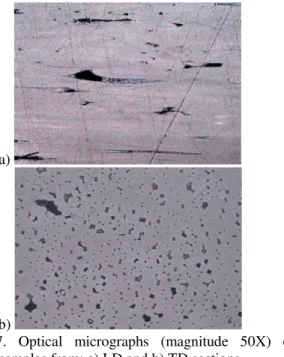
First attempts to consolidate laminate using a conventional consolidation pressure of 0.8 MPa led to considerable resin flow outside of the mold. Consolidation pressure was reduced to a minimum of 0.15 MPa to prevent matrix flow and hence loss of nanoparticle orientation within the PPNC fiber laminates. Laminates obtained showed a general fibrous appearance, indicating that complete melting of individual fibers did not totally occur. Optical micrographs taken in LD and TD sections, shown in Figure 7, reveal that the laminates contained a significant amount of voids between individual fibers. The presence of these voids indicates that consolidation conditions used, i.e., temperature and pressure, led to incomplete consolidation.
Flexural tests were then performed on the laminates in both LD and TD directions. The flexural stress – strain curves are shown in Figure 8. Numerical results are given in Table 1. These results show that a very clear anisotropic effect related to the fibrous structure of the laminates. The flexural modulus and strength increased respectively by approximately 40% and 250% when test direction changed from TD to LD. Test direction also affected fracture of the laminates. A sudden fracture occurring at approximately 1.0% was observed for TD while a progressive plastic deformation without sudden failure after more than 10% of deformation was observed for LD. Optical micrograph of a polished TD section of the fractured laminates is shown in Figure 9. A clear transverse crack that propagated between the PPNC fibers is shown in Figure 9. The crack propagation path coupled with the brittle failure observed in Figure 8 confirm that consolidation of the laminates was non-optimal.
Flexural results and mode of failure thus indicate that PPNC fiber orientation can be retained in consolidated 3D structures and that a significant reinforcement can be obtained from such fibers when oriented in pre-determined directions. Interestingly, modulus obtained from the laminates are significantly higher than modulus obtained from individual PPNC and PP fibers. Flexural modulus of laminates are also considerably higher than that of bulk PP or PNC, respectively of 50 and 58 MPa (7). More work is required to clarify this effect.
PET/HA fibers
SEM micrographs of PET/HA fibers produced are shown in Figure 10. X-ray results indicated that PET matrix was 100% amorphous while HA was 100% crystalline, in agreement with supplier’s specifications, as shown in Figure 11 for PET/HA with 10wt%.
Cellular viability in presence of these PET/HA fibers was characterized. Results are shown in Figure 12 for non-diluted extracts as dilution did not have an effect on the results. Figure 12 shows that cellular viability is of approximately 100%, which shows that PET-based fibers produced do not lead to cytotoxic reactions under MTT test conditions. It also shows that cellular viability is
constant for a given exposition period and that it is not affected by HA presence as all PET-based fibers tested present similar results. An interesting result is that cell viability is the same after 24 and 48 hours of exposition, but it significantly increases after 72 hours of exposition. Experiments are currently under way to duplicated these results and explain them.
These cellular viability results indicate that PET-based fibers, with or without HA particles, are good candidate materials for tissue engineering applications, especially in TRR. On-going work focus on build specific 3D structures for specific applications.
Conclusions
The results of this study lead to the following:
- PP-based PNC compounds can be transformed into fibers with improved mechanical properties related to both polymer and nanoparticles orientation;
- these fibers can be molded into 3D structure with retained improved mechanical properties in the direction parallel to fibers, which shows the potential of PNC fibers to produce high performance structural part with controlled anisotropy;
- fibers made of PET and PET/HA compounds can be produced;
- PET and PET/HA fibers do not lead to cytotoxic reactions and show sign of cell proliferation, which indicate that they are good candidate materials for tissue engineering applications.
References
1 Utracki, L. A. and M. R. Kamal, Arabian J. Sci. Eng. 27 44 (2002).
2 Park J. B. and R. S. Lakes. Biomaterials: An introduction, 2nd ed. New York: Plenum Press, 1992.
3 Vigolo B., A. Pénicaud, C. Coulon, C. Sauder, R., C. Journet, P. Bernier, P. Poulin. Science 290 1331-1334 (2000).
4 Dalton A. B., S. Collins, E. Muñoz, J. M. Razal, V. H. Ebron, J. P. Ferraris, J. N. Coleman, B. G. Kim, R. H. Baughman. Nature 423 703 (2003).
5 Mosmann T. 1983. J. Immunol. Methods. 65:55-63. 6 Bureau, M.N., F. Perrin-Sarazin and M.-T. Ton-That,
Polym. Eng. Sci, 44:6 1142-1151 (2004).
7 Ton-That M.-T., F. Perrin-Sarazin, M.N. Bureau, K.C. Cole, and J. Denault. Annual Technical Conference ANTEC 2005 (SPE), May 1-5 2005, Boston. 8 Cole, K.C. and A. Ajji, in Solid Phase Processing of
Polymers. Hanser Munich, 33-84 (2000).
9 Olley, R.H. and D.C. Basset. Polymer. 23 1707-1710 (1982).
Table 1. Flexural results from the laminates in the LD and TD directions. Flexural Property LD TD Modulus (MPa) 3440±130 2470±230 Strength (MPa) 74.8±1.4 21.6±0.9 Strain at Break --- 1.0±0.1
Figure 1. FE-SEM micrograph of PPNC fibers.
a)
b)
Figure 2. X-results shown as theta-2*theta plots superimposed on the 2D X-ray diagrams of: a) PP and b) PPNC fibers for approx. the same draw ratio of 23.
Figure 3. Similar plot at smaller angles (2theta < 10°) for PPNC showing a clay 001 peak between 2.5°and 3°and another at 4°. -0.4 -0.3 -0.2 -0.1 0 0.1 0.2 0.3 0.4 PP (110) PP (040) PNC (110) PNC (040) PNC (001) H e rm a n O ri e n ta ti o n fa c to r MD TD ND
Figure 4. Herman orientation factor calculated after ref (8) for PP reflections (110) and (040) in PP fibers and in PPNC as well as clay (001) reflection in PPNC.
Figure 5. FE-SEM micrograph of a polished and etched (after (9)) cross-section of a PPNC fiber showing clay preferential orientation. a) 0 500 1000 1500 2000 2500 0.0 10.0 20.0 30.0 40.0 50.0 60.0 70.0 Draw Ratio (---) T e n s il e M o d u lu s (M P a ) b) 0 10 20 30 40 50 60 70 80 90 100 0.0 10.0 20.0 30.0 40.0 50.0 60.0 70.0 Draw Ratio (---) T e n s il e S tr e n g th (M P a ) c) 0 100 200 300 400 500 600 0.0 10.0 20.0 30.0 40.0 50.0 60.0 70.0 Draw Ratio (---) E lo n g a ti o n a t B re a k (% )
Figure 6. Tensile properties of PPNC (diamond) and PP (square) fibers as a function of draw ratio: a) modulus, b) strength and c) elongation at break.
a)
b)
Figure 7. Optical micrographs (magnitude 50X) of polished samples from: a) LD and b) TD sections.
0 20 40 60 80 100 0 0.02 0.04 0.06 0.08 0.1 0.12 Flexural Strain (mm/mm) F le x u ra l S tr e s s (M P a ) LD TD
Figure 8. Typical flexural stress – strain curve of the laminates in the LD and TD directions.
Figure 9. Optical micrographs (magnitude 50X) of polished samples from TD sections after flexural testing.
Figure 10. SEM micrograph of PET/HA fibers.
Figure 11. X-results shown as theta-2*theta plots superimposed on the 2D X-ray diagrams for PET/HA fiber with a draw ratio of approximately 23.
0.0 20.0 40.0 60.0 80.0 100.0 120.0 140.0 160.0
PET0 PET2 PET4 PET6 PET8 PET10
C o lo r D e n s it y (% ) 24h 48h 72h
Figure 12. MTT tests results for PET fibers (PET0) and PET/HA fibers at 2, 4, 6, 8 and 10 wt% of HA (designated as PET2, PET4, PET6, PET8 and PET10) for exposition period of 24, 48 and 72 hours. Results are normalized (100% represent the same cellular viability as that of unexposed cells). (Reproduced with permission; S. Dimitriesvka, École Polytechnique, 2005).