Axiomatic Design of
Customizable Automotive Suspension Systems
byHrishikesh V Deo
B.Tech., Mechanical Engineering Indian Institute of Technology, 2001Submitted to the Department of Mechanical Engineering in partial fulfillment of the requirements for the degree of
Doctor of Philosophy in Mechanical Engineering at the
MASSACHUSETTS INSTITUTE OF TECHNOLOGY
February 2007© Massachusetts Institute of Technology 2006. All rights reserved
Author
/7
' eateto ehaia niern
' Department of Mechanical Engineering
October 25, 2006
Certified by &, -- 1 V I
Nam P Suh Ralph E. and Eloise F. Cross Professor of Mechanical Engineering
Accepted by MASSACHUSETTS INS'TTUTE. OF TECHNOLOGY
APR
I 9
2007
LIBRARIES
Lallit Anand Professor of Mechanical Engineering Chairman, Department Committee on Graduate StudentsAxiomatic Design of
Customizable Automotive Suspension Systems
byHrishikesh V Deo
Submitted to the Department of Mechanical Engineering
on October 25, 2006 in partial fulfillment of the requirements for the degree of Doctor of Philosophy in Mechanical Engineering
Abstract
The design of existing suspension systems typically involves a compromise solution for the conflicting requirements of comfort and handling. For instance, cars need a soft suspension for better comfort, whereas a stiff suspension leads to better handling. Cars need high ground clearance on rough terrain, whereas a low center of gravity (CG) height is desired for swift cornering and dynamic stability at high speeds. It is advantageous to have low damping for low force transmission to vehicle frame, whereas high damping is desired for fast decay of oscillations. To eliminate these trade-offs, a novel design for a customizable automotive suspension system with independent control of stiffness, damping and ride-height is proposed in this thesis. This system is capable of providing the desired performance depending on user preference, vehicle speed, road conditions and maneuvering inputs. The design, fabrication and control of the customizable suspension prototype are discussed. The application of variable stiffness and variable ride-height suspension system to achieve improved vehicle dynamics is studied. Application to control of vehicle dynamics parameters required bandwidth and power input beyond the capability of the first prototype. To eliminate the bandwidth restrictions of the prototype, a variable-stiffness pneumatic suspension system capable of instantaneous stiffness change with essentially no power input and no ride-height change, is developed. This is done by supporting the vehicle on air springs and connecting each air spring volume to multiple auxiliary volumes through On-Off valves. By adequately choosing N unequal auxiliary volumes, this system can achieve 2N stiffness settings. This suspension has been incorporated in a car suspension. The design, fabrication, and testing of the suspension system are reported in this thesis. A detailed frequency-domain model for the air-spring with auxiliary volumes is developed. Based on this modeling and testing, the performance limits and practical applicability of this system are discussed. The proposed variable stiffness isolator is capable of instantaneous stiffness change with no power input and no dimension change; moreover the isolator is inexpensive, robust and light. As a result, it is readily applicable to several other vibration isolation applications with conflicting stiffness requirements (such as a precision motion stages) or time-varying stiffness requirements (such as prosthetic limbs) and these applications are discussed.
Thesis Committee:
Professor Nam P Suh (Thesis Supervisor), Department of Mechanical Engineering, MIT Professor Samir Nayfeh, Department of Mechanical Engineering, MIT
Acknowledgements
First and foremost, I would like to thank my advisor and mentor Professor Nam Suh for all the guidance, support and sound advice- academic as well as personal. Most importantly, I would like to thank him for the confidence and trust he placed in me and my capabilities. Professor Suh has been a constamt source of inspiration for me and I will truly miss working with him closely. I could not have asked for a better mentor.
I would like to thank my committee member Professor Kamal Youcef-Toumi for very carefully reading my thesis. His comments and suggestions were extremely helpful in improving the manuscript. I am grateful for his help on modeling and controls aspects of the thesis, and in particular for the inspiration through his dedication and work-ethic. I would like to thank Professor Samir Nayfeh for his advice and direction. His thoughtful suggestions and constructive criticism, during the many "walk and talk" discussion sessions, have helped to shape my research. The funding for this research was provided by the Park Center for Complex Systems (PCCS), which was set up by the generous support of Dr. B J Park. I am grateful to Dr. B J Park for creating the Park Fellowship that supported my graduate studies. I would also like to thank the Ford MIT Alliance for supporting the initial part of this research. .
I would like to thank Dr. Richard Perdichizzi for going out of the way to let me use the Aero-Astro hanger to work on the car suspension prototype.
I consider myself fortunate to get an opportunity to work with an extremely talented research group over the last five years. Dr. Jason Melvin and Dr. Taesik Lee have been my mentors and close friends and I have often gone to them for advice. AJ Schrauth, Stephen Bathurst, Ishan Barman, Peter Jeziorek, Beto Peliks, Dr, Jeffery Thomas, Dr. Gyunyoung Heo, Dr. Christian
Habitch have also been my talented labmates and close friends. They helped to keep me motivated and moving.
Special thanks to Jason Melvin, Stephen Bathurst, Lawrence Maligaya, AJ Schrauth and Jordan Etra for all the help with fabrication. I would like to thanks Mark Belanger and Gerry Wentworth for helping me build the prototypes for my designs.
A number of friends at MIT have been instrumental in keeping me sane during my research and writing- including Binayak Roy, Ajay Somani, Brandy Worthington, Ashish Shah, Vickram Mangalgiri, Jason Melvin, Steve Bathurst, AJ Schrauth, Saif Khan, Sadaf Ansari, Waleed Farahat, Wayne Hsiao, Kyungyoon Noh, Jason Lapenta, and Blaise Gassend. Special thanks to Brandy for carefully reading and editing my thesis and all the help, support and encouragement during the most stressful stages of my thesis.
Finally, I would like to thank my Mom and Dad for all their love, support, encouragement and patience.
Contents
1 Introduction 13
1.1 Introduction to Axiomatic design 14
1.2 Introduction to existing suspension systems 15
1.2.1 Suspension kinematics 17
1.2.1.1 Dependent suspension systems 17
1.2.1.2 Independent suspension systems 18
1.2.2 Springs 20
1.2.3 Dampers 21
I1.2.4 Suspension dynamics models 22
.1.2.5 Prior art on active suspension systems 24
1.3 Thesis summary 26
2 Proposal of a novel Six-Bar Suspension 31
2.1 Introduction 31
2.1.1 Wheel Alignment Parameters 32
2.2 FRDP decomposition of vehicle system 33
2.2.1 Existing designs: Identification of coupling 36 2.2.2 Existing suspension systems: Four-bar linkages 37 2.2.3 Manifestation of coupling in existing systems 39
2.3 Proposed New Design 40
2.3.1 Proposed Design of a Suspension System 40
2.3.3 Application to suspension design 43
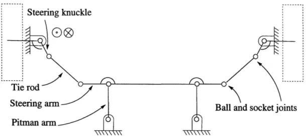
2.3.4 Proposed design of steering system 45
2.4 Evaluation of the proposed design 49
2.4.1 Advantages 49
2.4.2 Limitations 50
2.5 Summary 51
3 Customizable Automotive Suspension System 53
3.1 Introduction 54
3.2 Motivation for customizable suspension 56
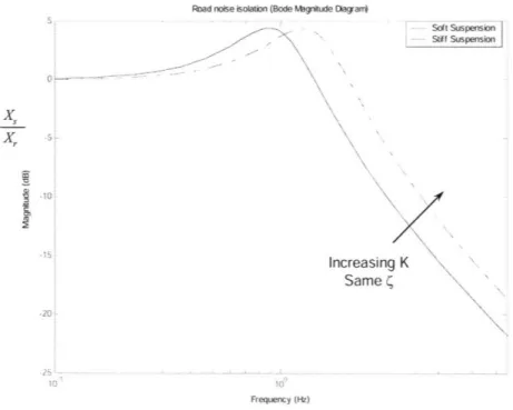
3.2.1 Need for variable stiffness: Effect of stiffness on suspension
performance 56
3.2.2 Need for variable ride-height 60
3.2.3 Prior art on variable stiffness and ride height 61
3.3 Proposed design for customizable suspension 61
3.3.1 Concept development 61
3.3.2 Prototype design and development 64
3.4 Control system design 66
3.4.1 Stiffness control 66
3.4.2 Ride-height control 66
3.5 Limitations: Motivation for instantaneous stiffness change 70
3.6 Summary 71
4 Design, Modeling and Fabrication of a Customizable Pneumatic Suspension
System 73
4.1 Basic cylinder and piston air-spring 74
4.1.1 Adiabatic stiffness 74
4.1.2 Isothermal stiffness 75
4.1.3 Polytropic stiffness 75
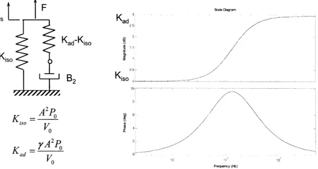
4.2 Proposed modifications to achieve independent control of stiffness and
4.2.1 Advantages of proposed design (Strategy 4) 81
4.2.2 Other potential applications 82
4.3 Reinforced flexible member springs construction 84
4.3.1 Convoluted/Bellows type air-spring 84
4.3.2 Rolling lobe or reversible sleeve type air-spring 86 4.3.3 Modified stiffness due to the effect of air-spring membrane 86 4.4 Detailed thermodynamic model to determine the frequency response of an
air-spring with auxiliary volumes 92
4.4.1 Thermodynamic modeling to estimate Damping due to the valve
flow resistance 94
4.4.2 Effect of valve damping on road noise isolation 99 4.4.3 Implementation issues with the solenoid valve arrangement 102 4.4.4 Modeling of effective inertia in the tubing 105 4.4.4.1 Incompressible flow assumption in pipe 106 4.4.4.2 Thermodynamic equations for air-spring and auxiliary
volume 107
4.4.4.3 Pipe flow equation 110
4.4.4.4 Estimates of the effective parameters in the model 116 4.4.4.5 Simulation of air-spring with complex stiffness model 117 4.4.4.6 Comparison with experimental results 119 4.4.5 Effect of inertia of air in pipe on road noise isolation for a
quarter-car SDOF model 120
4.4.6 Effect of inertia of air in pipe on road noise isolation for a
quarter-car 2DOF model 123
4.5 Suspension prototype 125
4.5.1 Fabrication/Implementation 125
4.5.2 Sensors and data acquisition 126
4.6 Experiments 130
4.6.1 Determination of lateral acceleration from body-mounted
accelerometers 131
4.6.3 Rear suspension deflection trends 135 4.6.4 Nonlinear force-deflection analysis for the air-spring 137 4.6.5 Cross-coupling between the two stiffness components 140
4.7 Limitations 142
4.7.1 Limited stiffness change and packaging issues 142 4.7.2 Time and power input requirements for stiffness change 144 4.7.3 Ride-height change due to unequal pressures in chambers 145
4.7.4 Modified stiffness control strategy 146
4.8 Summary 147
4.9 List of abbreviations and car parameters 149
5 Application to Improved Vehicle Dynamics 153
5.1 User customization of comfort and handling 154
5.1.1 Stiffness customization 154
5.1.2 Ride-height customization 155
5.1.3 Low-frequency attitude control: Ride-height change to uncouple
comfort and handling 155
5.1.4 Optimum performance over the entire speed range 156
5.2 Handling: Response to maneuvering inputs 157
5.2.1 Instantaneous stiffening change on hard braking, acceleration or
cornering to limit wheel attitude changes 157
5.3 Alteration of anti-dive and anti-pitch characteristics 159
5.4 Alteration of Understeer-Oversteer behavior 162
5.4.1 Cornering behavior of a simplified bicycle model 163
5.4.2 Suspension effects on cornering 166
5.4.3 Demonstration of capability to change understeer-oversteer
behavior on the fly 168
5.5 Alteration of pitch and bounce frequencies and the pitch and bounce
motion centers 169
6 Ride-Height Control and Stiffness Scheduling for Pneumatic Suspension 173
6.1 Ride-height control 174
6.1.1 Model for ride-height control 174
6.1.2 Control law 177
6.2 Stiffness scheduling 180
6.2.1 Determination of disturbance source from state measurements
exploiting phase relations 180
6.2.2 Scaling 184
6.2.3 Exponential forgetting 185
6.2.4 Stiffness scheduling based on r(T) 186
6.3 Summary 190
7 Conclusions 191
Chapter 1
Introduction
Suspension and steering systems have been in existence for centuries and they appeared on horse carriages long before the automobile was invented. As expected, this is a very mature field and there is a significant body of literature that deals with suspension and steering systems. Significant advances in design, modeling and analysis techniques, as well as materials and manufacturing technology have led to significant improvement in suspension performance over the decades. In spite of these advances, the main challenge in the design of suspension and steering systems still remains, and that is the trade-off that exists between the conflicting requirements of comfort and handling.
In the past few decades, due to advances in sensing, computation and actuator technology, active suspension systems have emerged as a very active field of research to eliminate this coupling between the comfort and handling requirements. This can be seen from the vast amount of literature in the field. There have been at least a dozen review papers that outline the state-of-art in the field (Elbeheiry et al., 1995; Hedrick & Wormely, 1975; Sharp & Crolla, 1987; Karnopp, 1995; Hrovat, 1997). In spite of the volume of this literature, the practical implementation of these ideas in automobiles has been limited. This is primarily due to the fact that the high actuator bandwidth requirements, power requirements, weight and cost increments, and reduced reliability are not justified by the limited incremental benefit to the passenger.
Our approach was to eliminate this trade-off by coming up with a very simple design that does not add significantly to the cost and complexity of the system, but at the same time provides perceptible benefit to the passenger. Axiomatic Design Theory (Suh, 1990; Suh, 2001) is used to identify the coupling that causes this trade-off and to come up with novel designs to eliminate this coupling.
1.1 Introduction
to Axiomatic design
Axiomatic design is a structured design method created to improve design activities by establishing criteria on which potential designs may be evaluated and by developing tools for implementing these criteria. Axiomatic design discusses the existence of four domains in the design world- customer domain, functional domain, physical domain and process domains. Customer attributes {CAs}, functional requirements {FRs}, design parameters {DPs}, and process variables {PVs} are the characteristic vectors of these domains. Design of products involves mapping from the functional domain to the physical domain and design of processes involves mapping from the physical domain to the process domain.
The axiomatic design process is centered on the satisfaction of functional requirements, which are defined as the minimum set of independent requirements that completely characterize the functional need of the product. Given a minimum set of independent FRs, the designer conceives a physical embodiment or a design containing a set of DPs, which are key physical variables in the physical domain that characterize the design that satisfies the specified FRs. The design and the choice of DPs are guided by the two design axioms.
* Axiom 1 (Independence Axiom): Maintain the independence of all functional requirements.
* Axiom 2 (Information Axiom): Minimize the information content of the design. The design matrix (DM) is used to note the effect of DPs on FRs as follows:
(FR 1 =Al
0
DP
(1.1)
FR 2 A2,1 A22
[DP
2
where All denotes the effect of DP 1 on FR 1, A21 denotes the effect of DP 1 on FR 2, etc. When the design equations represent conceptual design levels, it is common for the elements in the matrix Aij to be replaced with an 'X' if there is an effect and with an 'O' if there is not effect. To satisfy the Independence Axiom, the DM must be must be either diagonal or triangular. In an uncoupled design, the DM is diagonal and each of the FRs can be satisfied independently by adjusting one DP. In a decoupled design, the matrix is triangular and the independence of FRs can be guaranteed only if the DPs are determined in a proper sequence. In the case shown, we
need to set the DPs in the order: DP 1 followed by DP 2. A full design matrix leads to a coupled design and the satisfaction of FRs becomes difficult.
The Information Axiom guides the designer to maximize the probability of satisfaction of the FRs. It becomes increasingly difficult to satisfy FRs when FRs are coupled by the chosen DPs. This is because the allowable tolerance for DPs decreases with the increase in the number of FRs and the number of off-diagonal elements in the design matrix.
Axiomatic design begins with the most general requirements of the system, and decomposes these into sub-requirements. The goal of decomposition is the specification of a set of elements that will result in the parent. This involves moving back and forth between the functional and physical domains, and progressing from a general to a detailed description, and is referred to as zigzagging.
A direct consequence of Axiom 1 is Theorem 1 (Coupling due to insufficient number of DPs): "When the number of DPs is less than the number of FRs, either a coupled design results or the FRs cannot be satisfied". This coupling can be removed by addition of another DP.
1.2 Introduction
to existing suspension systems
In this section, a basic overview of existing suspension systems and suspension components is presented. In a practical suspension system, the wheel is connected to the car chassis through various links, which permit an approximately vertical motion of the wheel relative to the body. The motion of the wheel is controlled by the forces applied by the springs and dampers in passive suspension system. In active suspension systems, the springs and dampers are replaced by actuators which act as force producers according to some control law, using feedback from the vehicle. According to Gillespie (1992), the primary functions of a suspension system are to:
1. Provide vertical compliance so that the wheels can follow the uneven road, isolating the chassis from roughness in the road.
2. Maintain wheel attitude (characterized by wheel alignment parameters such camber, caster, toe etc.)
3. React to the longitudinal (acceleration and braking) and lateral (cornering) forces produced by the tires, as well as the braking and driving torques.
4. Maintain body alignment by minimizing roll and pitch motions of the car chassis 5. Maintain the tires in contact with the road with minimum load variations.
The corresponding FR/DP decomposition of the suspension system is given in Table 1.1. Table 1.1: FR/DP decomposition of suspension systems
Functional Requirements Design Parameters Parent Ensure comfortable ride Suspension system
1 Limit maximum relative motion Suspension stiffness
2 Dissipate energy Suspension damping coefficient
3 Set equilibrium position Spring initial length
4 Maintain wheel alignment Suspension kinematics
5 Maintain tire-road contact Suspension travel
DP 4: Suspension Kinematics is responsible for FR 4: Maintaining wheel alignment; while permitting an approximately vertical motion of the wheel. Wheel alignment is characterized by wheel alignment parameters (WAP) such as camber, caster, toe, steering axis inclination, caster offset, kingpin offset etc., which are shown in Figure 1-1 and will be explained in greater detail along with their effect on handling in Chapter 2.
Front
1.2.1 Suspension kinematics
Suspension kinematics are generally categorized into two groups- dependant suspensions (also known as solid axles) and independent suspensions.
1.2.1.1 Dependant suspension systems
In a dependant suspension system (solid axle suspension), the two wheels are mounted at either end of a rigid beam. The most common form of solid-axle suspension is the Hotchkiss drive as shown in Figure 1-2. As the two wheels are connected to each other, motion of one wheel is transmitted to the other wheel, and hence the name- dependant suspension system. Solid drive axles are used on the rear wheels of most trucks and on the front wheels of many four-wheel drive trucks. The drive axle is clamped to the leaf springs, and is driven through a longitudinal driveshaft with universal joints at the transmission and the axle. The leaf springs are mounted longitudinally and connect to the chassis at their ends.
Figure 1-2: Solid-axle leaf-spring rear suspension (Figure from Longhurst 2006)
Advantages of solid-axle suspensions are simplicity and fewer components, ease of assembly and manufacturing, high load capacity and insensitivity of camber to body roll. Disadvantages of solid-axle suspensions include higher unsprung weight and packaging constraints due to the large beam connecting the two wheels. The higher unsprung weight deteriorates suspension performance- comfort as well as handling. Moreover, the solid-axle makes it difficult to locate
the steering correctly and most solid-axle suspensions exhibit large bump steer, which is discussed in greater detail in Chapter 2. Other forms of solid axle suspensions include the four-link suspension system and the beam-axle suspension system.
1.2.1.2 Independent suspension systems
Independent Suspensions allow each wheel to move independent of the other wheel. Nearly all passenger cars and light trucks use independent front suspensions, because they provide more room for the engine in the front, and because of better resistance to steering vibrations (known as wobble and shimmy). They also provide higher roll stiffness relative to the vertical spring rate as compared to solid axles. Another major advantage is the significant reduction in unsprung weight, which leads to significant improvements in ride-quality. The most common types of independent
suspension systems are the short long arm (SLA) suspension and the MacPherson strut. Other examples include the swing axle suspension, trailing arm suspension, and multi-link rear suspension.
Swing Axle Suspension
Swing axles have universal joints connecting the driveshafts to the differential, which is attached to the chassis. They do not have universal joints at the wheels, and as a result the wheels are always perpendicular to the driveshafts. The swing radius is small and as a result they exhibit excessive camber change and tire-scrub (side-to-side motion of the tire-patch during the motion of the wheel) due to suspension travel as shown in Figure 1-3. This suspension also suffers from the problem of jacking. Jacking is caused during cornering when both tires are developing cornering forces, with the outer tire contributing greater cornering force and this inward force causes the vehicle CG to lift and reduces its rollover resistance. Due to these disadvantages, these were soon replaced by SLA suspensions.
Figure 1-3: Swing-Axle Suspension showing significant camber change due to suspension travel
--i 1
=0=
Short Long Arm Suspension
The most common independent suspension is the short long arm (SLA) suspension, also known as the double wishbone suspension. This uses two lateral control arms (A-arms or wishbones) of unequal lengths to hold a wheel as shown in Figure 1-4, and hence the name short long arm suspension. A simplified kinematic representation as planar four-bar linkage is also illustrated in Figure 1-4. The upper control arm is shorter than the lower control arm, to reduce the tire-scrub and to improve camber at the outside wheel by counteracting camber due to body-roll. It provides for excellent packaging for longitudinally oriented engines in front-engine rear-wheel-drive cars. Design of the geometry for an SLA is full of trade-offs and hence requires careful refinement to give good performance.
(f
Figure 1-4: Short long arm suspension system (a) 3D model (Figure from Longhurst 2006) and (b) Simplified representation as a planar mechanism
MacPherson Strut
The MacPherson strut is a telescoping member incorporating the spring and the damper with the wheel rigidly attached at its lower end as shown in Figure 1-5. The figure also shows a simplified kinematic representation as a planar four-bar linkage. The upper end of the strut is fixed to the chassis, and the lower end is located by linkages which pick up the lateral and longitudinal forces. The MacPherson strut, in addition to having fewer parts, provides major advantages in packaging for transverse engines and this is widely used for front-wheel-drive cars. As in the case of SLA
(I• \V/
suspension systems, design of the geometry for a MacPherson strut system is full of trade-offs and hence requires careful refinement to give good performance
(a) (b)
Figure 1-5: MacPherson Strut (a) 3D model (Longhurst 2006) and (b) Simplified kinematic representation as a planar mechanism
1.2.2
Springs
A variety of springs have been employed on existing suspension systems to achieve the desired
DP 1: Suspension stiffness. These include leaf springs, coil springs, air springs, and torsion bar springs.
Leaf springs are simple, robust and inexpensive. They were used on early automotive
suspensions such as the Hotchkiss suspension, and they are still common on some solid-axle suspensions on large trucks. The coulomb friction (stiction) in the individual leaves of the leaf spring leads to hysteresis and a much higher effective stiffness for small deflections (Sayers & Gillespie, 1982). This leads to a much harsher ride on smooth roads as compared to rough roads. Elongation of the leaf springs to lower spring rate, results in loss of side stability of the springs. Because of these disadvantages, they are not used on passenger cars anymore.
Coil springs are the most common type of spring on passenger cars for their simplicity, cost,
compact size and performance.
L---Torsion bar springs have been used on certain cars, where packaging constraints prohibit the use
of coil springs.
The use of pneumatic springs was first demonstrated in experimental car suspensions in 1935, but they have made inroads into commercial suspensions very recently. Some of their advantages are adjustable stiffness, adjustable ride-height, reduction of friction and nearly constant frequency with respect to load variations. A major portion of this thesis deals with the design and modeling of pneumatic springs and application of pneumatic springs to design a customizable automotive suspension with independent control of suspension stiffness and suspension ride-height.
1.2.3 Dampers
A variety of damper constructions have been employed on existing suspension systems to achieve DP 2: Damping Coefficient. Damping in suspension systems typically comes from viscous friction that results from the flow of fluid through a restriction in telescoping hydraulic dampers. Coulomb friction in the joints and bushings, and aerodynamic damping force on the body also contribute to the damping, but for analytical simplicity the damper is typically assumed to be a simple linear element with force proportional to velocity. The linear force-velocity relation is actually achieved with much difficulty in hydraulic dampers through suitable valving. In practice, the damping is linear but asymmetric, i.e., the damping in suspension rebound (extension) is typically two or three times the damping in suspension jounce (compression). This is achieved by using a piston that contains two orifices with one-way valves which provide different damping during jounce and rebound.
1.2.4 Suspension dynamics models
The effect of the DP 1: Suspension stiffness and DP 2: Suspension damping coefficient, on the comfort and handling performance of the car is the subject of suspension dynamics. In this section, we look at the different dynamic models used to study the effect of these parameters on the performance of passive suspension systems and the effect of the control law on the performance of active suspension systems. Several dynamic models have been used in literature to study the design and dynamic behavior of active and passive suspension systems. The choice of the model used depends on the vibration mode and frequency range of interest and the simplicity of analysis involved. Basic vehicle models that have appeared in the literature and
have been used in the design of suspension systems are quarter car 1-DOF model to study the bounce mode, quarter car 2-DOF model to study the bounce mode with wheel-hop, half car 4-DOF model to study bounce and pitch modes, and the full car 7-4-DOF model to study the bounce, pitch and roll modes. These models are described below:
1. Quarter car 1-DOF model: This is the simplest representation of an automotive suspension system at each wheel and captures the motion of the vehicle body at one wheel as shown in Figure 1-6 (a). The suspension is shown to have stiffness Ks, damping B and possibly an actuator (for active suspension) in parallel. The sprung mass Ms represents the quarter-car equivalent of the vehicle body mass, This model can be used to study only the vehicle bounce mode and fails to capture the wheel-hop mode. 2. Quarter car 2-DOF model: This model is shown in Figure 1-6 (b) and represents the
automotive suspension at each wheel, i.e., the motion of the axle and of the vehicle body at one wheel. The suspension is shown to have stiffness Ks, damping B and possibly an actuator (for active suspension) in parallel. The sprung mass Ms represents the quarter-car equivalent of the vehicle body mass, and the unsprung mass Mus represents the equivalent mass due to the wheel. The tire stiffness is represented by Kt. This model can be used to study the modes of vehicle bounce and wheel-hop. Xs, Xus, and Xr, represent the sprung mass displacement, unsprung mass displacement and the road deflection respectively. 3. Half car 4-DOF model: This model included the front and rear wheel to study bounce and
pitch mode. In Figure 1-6 (c), Xs and 0 represent the sprung mass bounce and pitch motions; Xusf and Xusr represents the unsprung mass displacement for the front and rear wheels respectively and Xrf and Xrr represents road deflection at the front and rear wheels respectively. The spring stiffness, damping and tire stiffness are denoted by K, B and Kt respectively.
4. Full car 7-DOF model: The models above can similarly be extended to a four wheel 7-DOF model to study the bounce, pitch and roll modes. The roll of the car is indicated by ý in Figure 1-7. Working with this model may become computationally expensive, so very often designers start with the simpler models and use the full car model to verily the design.
This thesis primarily deals with coming up with means to change suspension stiffness to
eliminate the trade-off involved in the conflicting requirements of comfort and handling. We will
primarily use the quarter car 1-DOF and 2-DOF models to study the effect of DP 1: Suspension
stiffness and DP 2: Suspension damping on the comfort and handling performance of a car. The
half car models will be used to study anti-pitch and anti-dive characteristics as well as
understeer-oversteer behavior of the car.
Ixs
_X,
IXf IXrFigure 1-6: Suspension dynamics models (a) Quarter car 1-DOF model; (b) Quarter car 2-DOF model; and (c) Half car 4-DOF model
Br
_j
XUS(lr)
-J Yorar
1.2.5 Prior art on active suspension systems
Active vehicle suspensions have attracted a large number of researchers in the past few decades and comprehensive surveys on related research can be found in the papers by Elbeheiry et al (1995), Hedrick and Wormely (1975), Sharp and Crolla (1987), Karnopp (1995), and Hrovat (1997). These review papers classify various suspension systems discussed in the literature as passive, active, semi-active, slow-active, self-leveling and adaptive systems.
* Passive suspension systems: In passive suspension systems, the vehicle chassis is
supported by only springs and dampers, which apply forces proportional to suspension displacement and suspension velocity respectively.
* Active suspension systems: Active suspension systems (fully active or high frequency
active) replace, in part or full, the springs and dampers of passive systems by actuators. These actuators act as force producing elements according to some control law, using feedback from the vehicle. The actuator control bandwidth is assumed to extend beyond the wheel hop frequency, which is typically 8-10 Hz.
* Semi-active suspension systems: Semi-active suspension systems are considered to be
derived from active systems, with the actuator replaced by controllable damper and a passive spring in parallel. It is assumed that the force-velocity relation can be modulated at relatively high frequencies. These systems employ feedback control to track the force demand signal which is similar to a corresponding active system, except that in circumstances where the active system would supply work, the force demanded of the damper is zero.
* Slow-active suspension systems: Slow-active suspension systems (also known as "low
frequency active") use actuator bandwidths in the range of body resonant frequencies in bounce, pitch and roll, and the frequency range of interest as far as responses to steering control are concerned, but lower than the wheel hop frequency. Actuators may be of one of the two basic types. They can be flexible like a spring when they become inactive in a control sense beyond the bandwidth, in which case they can support the body weight or act in parallel with the spring. Or they can be rigid when inactive in which case they must be mounted in series with the spring. Pneumatic actuators belong to the first category. Hydraulic actuator, electric motor or irreversible lead screw actuators belong to the
second category and are typically modeled as a displacement producer rather than a force producer.
* Preview suspension systems: Preview suspension systems involve acquisition and use of
information of the road profile ahead of the vehicle wheels for actuator control purpose. These typically rely on high bandwidth actuators and accurate sensors; and have achieved limited success.
* Adaptive suspension systems: Adaptive suspension systems are essentially passive
systems in which the parameters of the system can be changed in response to some information.
* Dynamic vibration absorbers have also been used in passive as well as active (Hrovat, 1997; Hrovat, 1990) suspension systems to get improved performance.
The applicability of fully active suspensions is restricted as the size, weight, power requirements and cost increase prohibitively with the bandwidth of the actuators. Semi-active suspensions have only dissipative elements and slow-active suspensions are band-limited; and hence are limited in their capabilities. In this thesis, we will focus on adaptive suspension systems. These are essentially passive systems in which the parameters of the system can be changed on the fly. Karnopp and Margolis (1984) have discussed the effects of parameter variation on frequency response and proposed that suspensions with adaptive stiffness and damping coefficient have potential in improvement of ride comfort and handling. Damping control, typically achieved through orifice control, is an established technology in existing vehicles (Crosby & Karnopp, 1973; Karnopp, 1983). Several road vehicles with pneumatic springs are capable of achieving variable ride-height (Esmailzadeh, 1979; Chance, 1984). Although advantages of variable stiffness, have been illustrated in literature (Karnopp & Margolis, 1984), no system with independent control of stiffness has been proposed so far. In Chapters 3 and 4, we have proposed designs for novel customizable automotive suspension system with independent control of stiffness, damping and ride-height, which is capable of providing the desired performance depending on user preference, road conditions, vehicle speed, and maneuvering inputs.
In automotive suspension optimization literature, road noise is considered as a disturbance input. Different performance metrics such as sprung mass velocity, suspension deflection and tire-deflection are included in the cost as measures of comfort, suspension rattle-space and
road-holding. Different optimization techniques (predominantly LQG) are used to determine the control law for fully active suspensions. These techniques have been modified for application to optimization of passive suspension system parameters. Inertial forces due to maneuvering inputs are never included as they are difficult to model as stochastic disturbances. But this is not a reasonable assumption as the inclusion of inertial forces is the most important factor for handling performance optimization. In Chapter 6, we have presented stiffness scheduling for the variable-stiffness suspension systems proposed in Chapters 3 and 4, including both road noise and inertial forces caused by maneuvering inputs in the optimization formulation.
1.3
Thesis Summary
In this thesis, we have investigated the application of Axiomatic Design approach to eliminate the coupling that causes the trade-off between the conflicting comfort and handling requirements. Road noise isolation is defined as a performance metric for comfort; and the extent of lateral destabilizing forces caused due to wheel alignment parameter changes is defined as a performance metric for handling.
The first coupling in the suspension system that has been addressed in this thesis manifests itself through the wheel alignment parameter changes caused by suspension travel. Wheel alignment parameter changes lead to lateral destabilizing forces and increased tire-wear. The four-bar linkages used in the existing independent suspension systems (namely the SLA suspension and the MacPherson strut) are not capable of avoiding the wheel alignment parameter changes due to suspension travel. In Chapter 2, a six-bar Watt-I linkage suspension is proposed which is capable of making the wheel alignment parameters independent of suspension travel thereby eliminating lateral destabilizing forces and tire-wear. As a result a softer suspension may be used without affecting handling adversely. A formulation for kinematic synthesis of the suspension system using the six-bar Watt-I linkage is outlined and a new steering system compatible with the new suspension system is proposed. This design has great promise for improved comfort and handling and reduced tire-wear on straight-ahead driving conditions, but exhibits unfavorable camber change on cornering. This indicates that changing single degree of freedom suspension kinematics may have limited benefit in eliminating this coupling.
The second coupling, addresses in this thesis, is caused due the fact that the same DP:
to coupling as handling requires a stiff suspension, whereas comfort requires a soft suspension. In this thesis, we eliminate this coupling by separating the DP: Suspension stiffness in time. This can be done by designing a suspension system with time-varying stiffness, such that the vehicle has low stiffness when comfort is of primary importance, and has high stiffness when handling is of primary importance. Moreover, the tradeoffs in selection of ride-height and damping are also considered. Cars need high ground clearance on rough terrain, whereas a low center of gravity (CG) height is desired for swift cornering and dynamic stability at high speeds. It is advantageous to have low damping for low force transmission to vehicle frame, whereas high damping is desired for fast decay of oscillations. To avoid these trade-offs, a novel design for a customizable automotive suspension system with independent control of stiffness, damping and ride-height is proposed in Chapter 3. This system is capable of providing the desired performance depending on user preference, road conditions and maneuvering inputs. A prototype has been designed and fabricated to demonstrate the concept. The structure of the design matrix is shown in Equation (1.2).
FRI: Control Stiffness t=[X O DP1 ( Design) (1.2)
FR2: Control Ride-height X X DP2
The proposed system employs a linear stage to move the lower spring pivot along the lower control arm to achieve the desired stiffness change. This system presents cost, robustness and unsprung mass issues. Moreover this system is designed for slow changes in stiffness to satisfy the constraint of low power requirement. But application of variable stiffness suspension system to improved vehicle dynamics suggested that much greater benefit could be derived if the stiffness change is instantaneous (rapid) and if stiffness change does not affect ride-height. The design matrix for the existing suspension system shows that stiffness change affects ride-height change. Although this can be compensated for by DP 2, the compensation involves energy input and time-delay. Hence it is preferable to have an uncoupled design as shown in Equation (1.3). In case an uncoupled design is not possible a decoupled design with the design matrix structure as shown in Equation (1.4) is preferable over a design matrix structure as shown in Equation (1.2).
FRI: Control Stiffness X 0]DP1 (Ideal Design) (13)
FR1: Control Stiffness
X X DP B
FR2: Control Ride-height = X DP B (Preferred over 1st Design) (1.4)
FR2: Control Ride-height j O X DP2 B
In chapter 4, we have investigated the possibility of using pneumatic and hydro-pneumatic suspension systems to create a customizable automotive suspension with independent control of stiffness, damping and ride-height; preferably with instantaneous (or rapid) stiffness change, with no (or limited) power input and no (or limited) effect on ride-height change as described in the design matrix in Equation (1.4). One of the proposed designs employs auxiliary volumes
connected to the air-spring volume through On-Off valves for changing the stiffness of the system. The stiffness of an air-spring is inversely proportional to the volume of air in the air-spring. When the valve is opened, the air-spring stiffness reduces due to increase in effective volume. By adequately choosing N unequal auxiliary volumes, this system can achieve 2N
stiffness settings. This system shows the potential of instantaneous stiffness change, with no power input, and no ride-height change due to stiffness change. Moreover, the proposed variable stiffness isolator is inexpensive, robust and light. As a result, it is readily applicable to several other vibration isolation applications with conflicting stiffness requirements (such as a precision motion stages) or time-varying stiffness requirements (such as prosthetic limbs). These applications are also discussed in Chapter 4.
A customizable pneumatic suspension system prototype has been designed and incorporated in a car and it demonstrates the concept well. A data acquisition system has been designed and incorporated in the car for testing the performance of the pneumatic suspension system. The design, fabrication, and testing of the suspension system is discussed in Chapter 4. A detailed thermodynamic model of the air-spring with auxiliary volumes is developed to predict the frequency response of the system for small displacements. For large displacements, the linear stiffness model is no longer valid. This may lead to counter-intuitive behavior such as increase in stiffness when valves are opened. The nonlinear force-displacement relations are derived for an air-spring with auxiliary volumes and they explain the observed data well. Based on this modeling and testing, the performance limits and practical applicability of this system are discussed.
The capability to change stiffness instantaneously and with no power input, allows us to employ a soft suspension on rough roads during straight-ahead driving conditions, and to instantaneously
increase stiffness on hard braking, hard acceleration or cornering to limit the wheel attitude changes and vehicle attitude changes. In Chapter 5, the applications of the customizable suspension systems, capable of low bandwidth stiffness change and high bandwidth (instantaneous) stiffness change, are discussed. Here high bandwidth stiffness change refers to stiffness change that is much faster than the time constants associated with the relevant rigid-body modes of the system, namely bounce, pitch, roll and yaw modes. The application of variable stiffness to achieve real-time alteration of pitch and bounce motion centers, and real time alteration of anti-pitch characteristics is demonstrated. The possibility of ensuring stability through real-time alteration of understeer-oversteer characteristics is explored and demonstrated on the pneumatic customizable suspension system. The suspension geometries (kinematics) and stiffness settings required for achieving the desired vehicle dynamic characteristics (such as anti-pitch/anti-dive characteristics, understeer-oversteer characteristics or pitch and bounce motion center locations) are well known. But the geometries required for the different characteristics are very often contradictory and this leads to a trade-off solution for the suspension kinematics. The capability of rapid real-time alteration of these characteristics allows us to eliminate the design coupling involved.
In Chapter 6, ride-height control of a constant area pneumatic suspension system is discussed. The response of this nonlinear system to the valve On-Off control is modeled and it is observed that a feedback control law using only position feedback leads to a limit cycle. A modified state feedback control law using position and pressure feedback is proposed to ensure convergence to the equilibrium point.
In automotive suspension optimization literature using LQG/H2 techniques, road noise is considered as a disturbance input, and sprung mass velocity, suspension deflection and tire-deflection are included in the cost as measures of comfort, suspension rattle-space and road-holding. Inertial forces due to maneuvering inputs are never included as they are difficult to model as filtered white noise. But this is not a reasonable assumption as the inclusion of inertial forces is the most important factor for handling performance optimization as was seen from the six-bar example. The second part of Chapter 6 discusses stiffness scheduling based on the hypothesis that the optimum stiffness depends on the source of disturbance- road noise or inertial forces due to maneuvering inputs. In this chapter, an attempt is made to determine the source of
disturbance from state measurements by exploiting phase relations, and to schedule the stiffness to the optimum value based on the source of disturbance.
Chapter 2
Proposal of a novel Six-Bar Suspension
2.1 Introduction
Existing vehicle suspension and steering system designs exhibit a high level of coupling. For instance, the coupling in suspension and steering systems manifests itself through the change in wheel alignment parameters (WAP) due to suspension travel. This change in the wheel alignment parameters causes directional instability and tire-wear. The approach of the industry to solve this problem has been twofold. The first approach has been the optimization of suspension link lengths to reduce the change in wheel alignment parameters to zero. Since this is not possible with the existing architecture, the solution used is the optimization of the spring stiffness to get a compromise solution for comfort (which requires soft suspension for good road-noise isolation) and directional stability (which requires a stiff suspension for minimizing wheel travel to reduce wheel alignment parameters variation).
In this chapter, an axiomatic design solution to this problem is presented and an attempt is made to remove the coupling in the steering and suspension systems by making the wheel
alignment parameters independent of suspension travel. The four-bar linkages used in the existing independent suspension systems are incapable of satisfying their FRs independently and cause coupling at a higher level. The proposed solution uses a six-bar Watt-I linkage suspension, which eliminates this coupling. It also offers other advantages such as the hardening characteristics for the suspension. A new steering system conformal to the new
FR/DP decomposition of the vehicle systems is presented. This indicates other couplings and DP redundancies in the vehicle system and also provides the framework for design of novel vehicles.
2.1.1 Wheel Alignment Parameters
As mentioned earlier, the extent of lateral destabilizing forces caused by wheel alignment parameter changes is defined as a performance metric for handling. In this section we define the wheel alignment parameter and their effect on handling. Orientation of the wheels and steering axes with respect to the vehicle frame and with respect to the terrain changes due to suspension travel (Gillespie, 1992; Bastow, 1987; Dixon, 1996). Figure 2-1 shows the wheel alignment parameters which describe the orientation of the wheel and the wheel axis.
Camber: Camber is defined as the angle the wheel makes with respect to the vertical as seen in
the front view. Camber tends to lift up one side of the tire and the higher load on one side of the tire leads to increased tire-wear. The tire assumes the shape of a base of the cone during rotation leading to a lateral force known as camber thrust. As a result camber spread (unequal camber on left and right wheels) causes directional instability.
Toe angle: Toe angle is the angle between the wheel and the vehicle longitudinal axis as seen
in the top-view (denoted by xg in Figure 2-1), and is used to steer the vehicle. In existing suspension systems, toe changes due to suspension travel, leading to Bump Steer as shown in Figure 2-10. Excess toe causes tire-wear.
Caster: Caster is the angle the steering axis makes with respect to the vertical as seen in the side view. Caster spread (unequal caster on left and right) causes directional instability.
Steering Axis Inclination: Steering Axis Inclination (SAI) is the angle the steering axis makes with respect to the vertical as seen in the front view. The forces acting on the wheel create a moment of the steering linkage which depends on the SAI and the kingpin offset. These determine the stability of a vehicle in high speed straight-ahead driving situations. Changes in steering axis inclination and the kingpin offset, due to suspension travel, cause directional instability.
As a result of these factors, vehicles exhibit tire-wear and directional instability due to wheel alignment parameter changes caused by suspension travel under conditions of overload, offset load or road undulations. Our approach to solve this problem is to perform a FR/DP
decomposition of the system, identify the coupling that causes the problem and to eliminate the coupling through proposal of a new design.
Front
offset
Figure 2-1: Wheel Alignment Parameters
2.2
FRDP
decomposition of vehicle system
The top level F R/DP decomposition for the vehicle system is shown in Table 2.1 and the corresponding design matrix (DM) is shown in Equation (2.1). The DM indicates two sets of couplings- coupling between FR 3 and FR 5 and coupling between FR 4 and FR 5. The effect of DP 5 on FR 3 is small, as indicated by x in the DM in Equation (2.1). The design works in spite of this coupling, due to the presence of a feedback control system- the driver. Identification and removal of the coupling between FR 4 and FR 5 is the subject matter of this chapter. These two FRs have been decomposed further to understand this coupling better. FR 4: Hold passengers can be further decomposed as shown in Table 2.2. As indicated in the decomposition, the passenger compartment must provide safety, comfort and pleasure to the passenger. Further decomposition of FR 42: Ensure comfortable ride is shown in Table 2.3. The corresponding design matrix is given in Equation (2.2).
Table 2.1 : Top level FR/DP decomposition of vehicle system
Functional Requirements Design Parameters
Parent Need for transportation Vehicle system
1 Allow low resistance motion Rolling motion (Wheels)
2 Hold cargo Cargo space
3 Control speed Wheel rotation speed
4 Hold passengers Passenger space
5 Control direction Turning torque
6 Attractive appearance Exterior Bodywork
FRi1 X O O O O O DP I FR 2 X X 0 0 0 0 DP 2 FR33 X 0 X 0 x 0 DP 3 FR44 X 0 X X X 0 DP 4 FR 5 X 0 X X X 0 DP 5 FR6 X X 0 X X X DP61
Table 2.2 : FR/DP decomposition of FR 4 (Hold passengers)
Functional Requirements Design Parameters
4 Hold passenger Passenger compartment
41 Provide crash protection Impact strength 42 Ensure comfortable ride Suspension dynamics 43 Provide pleasing environment Interior design Table 2.3 : FR/DP decomposition of FR 42 (Ensure comfortable ride)
Functional Requirements Design Parameters 42 Ensure comfortable ride Suspension dynamics 421 Limit maximum relative motion Spring rate
422 Dissipate energy Damping coefficient
423 Set equilibrium position Spring initial length
FR1421
X O
O]DP1421
FR 1422 X X O DP 1422 (2.2)
FR 1423
X O X DP 14231
FR 5 (Control direction) can be further decomposed as shown in Table 2.4 and the corresponding design matrix is given in Equation (2.3).
Table 2.4 : FR/DP decomposition of FR 5 (Control direction)
Functional Requirements Design Parameters
5 Control direction Turning torque
51 Maintain wheel alignment Suspension kinematics 52 Maintain tire-road contact Suspension travel
53 Adjust desired torque Wheel angle
FR 51
X
0
0
DP 51
FR 52 X DP 52 (2.3)
FR 53 X O X DP 53
In several complex systems, the design matrix (DM) may be coupled at the highest level as shown in Equation (2.4), which on further decomposition of FRexl and FRex2 can be expressed as Equation (2.5). FRex X
X]{
DPex,1(2.4)
FRex 2 X XJ DPex2FRexIl I X
0 0
0 1DPex
1
1
FRexl2
XX
X DPexl2
(2.5)
FRex21
X
O X
0
DPex21
FRex 22 LX 00
X DPex 22
The structure of the design matrix in Equation (2.5) is such that we can rearrange the order of the leaf level DPs to achieve a decoupled design matrix as shown in Equation (2.6). This method is known as system-wide rearrangement of the DPs and FRs and can be used to decouple an apparently couple system (Melvin & Suh, 2002). In several complex systems, a coupled design matrix at the highest level may be decoupled by system-wide rearrangement of the DPs and FRs.
FRexll
X 0
O00
DPex11
FRex22 XX OO DPex22 (2.6)
FRex 21
X 0 X
0
DPex21
FRex12J
X
XXX LDPexl2In this example, we observed that it is difficult to create a design which would eliminate the coupling between FR 4 and FR 5 at the highest level. But it is possible to have a decoupled system after decomposition and system-wide rearrangement. To illustrate this, FR 42 and FR 5 are decomposed together and the corresponding design matrix presented in Equation (2.7).
FR 51 X X1 X3 0 0 0 DP 51 FR 52 X X 0 0 0 0 DP 52 FR 421 X 0 X 0 0 0 DP 421 FR 422 X 0 X X 0 0 DP 422 (2.7) FR 423 X 0 X 0 X 0 DP 423 FR53, X X2 X4 0 0 X DP53
2.2.1 Existing designs: Identification of coupling
The elements X1, X2, and X3 in the design matrix in Equation (2.7), indicate the coupling. X1
indicates that suspension travel causes the wheel alignment parameters to change and this causes undesired turning torque changes, as indicated by X2. The extent to which the wheel alignment parameters change and hence the magnitude of the unwanted turning torques change depends on the spring stiffness. This interaction is indicated by the elements X3 and X4. Note
that X2 being non-zero does not make the design matrix coupled. But DP 52: Suspension travel
is a dynamic design parameter and it affects FR 53 (Adjust desired torque). Hence, to satisfy FR 53, we would require real-time adjustment of DP 53 (Wheel angle). To avoid this, we need a design that is uncoupled with respect to the dynamic design parameter DP 52 (XI=0, X2=0).
These elements can be made zero and the coupling can be removed by making the wheel alignment parameters independent of suspension travel. The next sub-section examines the changes in wheel alignment parameters that result from suspension travel in the existing designs, lists the problems caused by this coupling and explores the possibility of removing this coupling by making the WAP independent of suspension travel.
2.2.2 Existing suspension systems: Four-bar linkages
All existing front-wheel independent suspension systems are variations of the four-bar
mechanism. For instance, the parallel arm suspension, the short long arm (SLA) suspension and the MacPherson strut suspension can be kinematically represented as shown in Figure 2-2.
Parallel Arm Suspension LSA Suspension McPherson Strut
Figure 2-2 : Kinematic representation of independent suspensions
The FRs that DP 51: Suspension Kinematics (Four-bar linkage) is expected to satisfy are given in the form of FR/DP decomposition in Table 2.5 and are indicate in Figure 2-3. Ay indicates the lateral motion of the tire-patch (commonly known as "track changes") caused by suspension travel. Aý indicates the changes in the inclination of the steering axis as seen in the front view. We will only look into the following three important FRs for simplifying the analysis in this chapter: FR 511: Provide relative Z-motion, FR 512: Avoid track changes (Ay=0) and FR 513: Avoid camber and caster changes (Aý =0). Here Ay indicates tire scrub and A4 indicates camber change. The other FRs are uncoupled and can be easily satisfied independently.
Table 2.5 : FR/DP decomposition of FR 51 (Maintain wheel alignment) Functional Requirements Design Parameters
51 Maintain wheel alignment Suspension kinematics
511 Permit relative Z-motion Single degree of freedom system 512 Avoid track changes (Ay=0) Effective swing axle radius
Analysis of the parallel arm suspension shows that it is capable of providing relative Z motion by change of angle 0 as shown in Figure 2-4 and can maintain A4=O as both joints of the steering axis have equal vertical motion during suspension travel. But the parallel-arm suspension is incapable of satisfying FR 512: Ay=O during suspension travel. This causes excessive tire-scrub due to suspension travel as illustrated in Figure 2-4. This sideways motion of the tire causes unnecessary tire-wear. It also causes the tire slip angle to change without any toe and results in destabilizing lateral forces.
In the SLA suspension, we can achieve Ay=O (no tire scrub) through assignment of appropriate values to the link lengths, but this doesn't allow Aý=0 during suspension travel. This causes camber change and caster change due to suspension travel (Bastow, 1987). A compromise solution for Ay and Aý can be obtained through optimization of the link lengths and joint positions, but we cannot satisfy all three FRs simultaneously using a four bar linkage. Both Ay and Aý can be reduced by increasing the link lengths, but this is limited by the constraints of cost, packaging and unsprung weight of the vehicle
S(FR
513 A =0)
Z (FR 511)
A RD 51 A A
I Z
Figure 2-4 :: Kinematic representation of parallel-arm suspension showing tire-scrub
The MacPherson strut suspension, also a four-bar linkage with one prismatic joint, is incapable of satisfying the three FRs simultaneously as well. It exhibits tire-scrub as well as WAP changes due to suspension travel.
This implies that in the existing designs, suspension travel affects the WAP. This makes the system coupled as indicated by the elements X1, X2 and X3 in Equation (2.7). This coupling
leads to several problems. The changes in camber angle and toe due to excess suspension travel under overload causes unnecessary tire-wear. This could be a serious issue in trucks as the WAP could change significantly from unloaded to fully loaded condition. Under offset load, different suspension travel for the wheels could cause camber spread, caster spread or toe spread leading to directional instability or Drift/pull of the vehicle. Toe change due to suspension travel causes Bump Steer due to road undulations. Toe change due to suspension travel is also a possible source for the Nibble problem, in which the high frequency road noises are transmitted back to the steering wheel.
2.2.3 Manifestation of coupling in existing systems
Very often in coupled designs, when one DP affects two or more FRs, these FRs require the DP to have different values. This leads to a trade-off between the conflicting FRs and the designer has to resort to optimization of the DPs to achieve the best compromise solution. The coupling in the automobile suspension and steering system is manifested by the following trade-offs to achieve compromise solutions:
1. Compromise between AO=0 and Ay=O through optimization of link lengths.
2. Compromise between comfort and handling through optimization of spring stiffness K. Handling requires a stiff suspension, whereas comfortable ride requires a soft suspension. Since the existing designs cannot make the wheel alignment parameters independent of suspension travel, optimization of the spring stiffness has been the approach of the industry to get a compromise solution for FRs of comfort and handling. The axiomatic design approach points out the coupling between the FRs and indicates the need for developing a new uncoupled solution so that the compromise can be eliminated. Axiomatic design theory suggests the need for a new design that can satisfy both A4=O and Ay=O simultaneously. Such a design would make the wheel alignment parameters independent of not only the suspension travel, but also of spring stiffness. Hence the control of the vehicle will improve. This will lead to improved handling. Spring stiffness can be designed only from comfort considerations and this will also improve passenger comfort.
2.3 Proposed new design
This section discusses the new suspension and steering system proposed to remove the identified coupling.
2.3.1 Proposed design of a suspension system
Analysis in the previous section indicated that the four-bar linkage is incapable of satisfying all three FRs (provide suspension travel, maintain A-=O and maintain Ay=O) simultaneously. This leads to coupling at a higher level. The DM indicates that the coupling can be removed by a change of DP 51: Suspension kinematics (Four-bar mechanism). A decision was made to change to DP 51: Suspension kinematics (Single degree of freedom system). Stating this as the DP presents several single degree of freedom systems as options for the hardware of the suspension kinematics, namely- a single revolute or prismatic joint, six-bar linkage and so on, apart from the four-bar linkage.
A prismatic joint is used in two wheeler suspensions, but there are issues involved in incorporating it in an automobile suspension. Revolute joint is used in the swing-axle suspension and it is capable of meeting only one FR out of the three FRs simultaneously. In a