HAL Id: hal-02494048
https://hal.archives-ouvertes.fr/hal-02494048
Submitted on 28 Feb 2020
HAL is a multi-disciplinary open access
archive for the deposit and dissemination of
sci-entific research documents, whether they are
pub-lished or not. The documents may come from
teaching and research institutions in France or
abroad, or from public or private research centers.
L’archive ouverte pluridisciplinaire HAL, est
destinée au dépôt et à la diffusion de documents
scientifiques de niveau recherche, publiés ou non,
émanant des établissements d’enseignement et de
recherche français ou étrangers, des laboratoires
publics ou privés.
AN ACCURATE APPROACH OF THE
NITRIDATION PROCESS OF TiSi 2 POWDER
Simon Le Ber, Laurence Maillé, Francis Rebillat, Marie-Anne Dourges,
Patrick Weisbecker, Christine Picard, René Pailler
To cite this version:
Simon Le Ber, Laurence Maillé, Francis Rebillat, Marie-Anne Dourges, Patrick Weisbecker, et
al.. AN ACCURATE APPROACH OF THE NITRIDATION PROCESS OF TiSi 2 POWDER.
Walter Krenkel. High Temperature Ceramic Materials and Composites, AVISO Verl.-Ges, 2010,
9783000320491. �hal-02494048�
AN ACCURATE APPROACH OF THE NITRIDATION
PROCESS OF TiSi
2POWDER
Simon Le Ber, Laurence Maillé, Francis Rebillat, Marie-Anne Dourges, Patrick Weisbecker, Christine Picard, René Pailler
Université de Bordeaux 1, LCTS, 33600 Pessac, France
Abstract
A work based on the study of nitrogen diffusion in a micrometer-sized powder of TiSi2 is reported in this paper. In order to provide accurate
information about the various reaction mechanisms involved with the transformation process of this powder, TiSi2 is treated under nitrogen flow, at
1100°C, during various nitridation times. The structure of this powder is characterized by X-Ray Diffraction (XRD). Transverse sections of grains, prepared using ion polishing system (Cross Polisher JEOL Ltd), are observed with an Environmental Scanning Electron Microscope (SEM) whereas the chemical composition is analyzed by Energy dispersive X-ray spectroscopy. All these analyses have underlined that under a nitrogen flow, TiSi2 is transformed into nanograins of TiN at the extreme surface,
surrounding silicon inside the grain. These results are discussed in term of various diffusion limitation phenomena: nitrogen through TiN and titanium through silicon, according to phases equilibria. During oxidation of nitridated TiSi2, the less resistance phase and the more exposed phase to oxygen
supply TiN and Si, are oxidizing in TiO2 and SiO2. This latter part is
demonstrated in-situ using the SEM.
Introduction
Titanium and its alloys are attractive to the aerospace and chemical industries because they possess superior specific strength and a good corrosion resistance [1]. Titanium disilicide (TiSi2) is also used in
microelectronic industry on account of its low electrical resistivity, high thermal stability, and chemical and structural compatibility (small lattice mismatch) with silicon substrate [2-4]. TiSi2 powder can also be introduced in
ceramic matrix composite (CMC) fabrication route. In order to be competitive on civil aeronautic market, low cost CMC processing as liquid phase route including polymer impregnation/pyrolysis were developed. But an inherant shrinkage is observed after pyrolysis of the polymer, even when powders are inserted in the matrix. P. Greil suggested overcoming this problem with addition of active fillers, which react during pyrolysis to form oxides, carbides or nitrides leading to volume expansion [5-15]. Titanium disilicide (TiSi2,
density = 4.01 g/cm3) has been identified as an interesting active filler. Indeed, under nitrogen atmosphere, TiSi2 can form TiN (d = 5.43 g/cm
3
) and Si3N4 (d = 3.19 g/cm
3
); going with a 57% volume increase. Some studies are performed in our group to prepared ceramic composites with a smaller size powder obtained by ball-milling [16-17]. To control the process, nitridation of TiSi2 must be well known. In this paper, we explore the influence of
temperature and time on the nitridation rate of a micrometer-sized TiSi2
powder. Oxidation behavior of nitrided TiSi2 is presented too.
Materials and experimental procedure
A high purity micrometer-sized TiSi2 powder (C-54 stable phase, 99.95% in
purity, ~45µm, Neyco) is used in this work. A study of XRD patterns shows the presence of 8.6%wt of free silicon and 91.4% wt of TiSi2 phase.
This powder is heated under nitrogen atmosphere at a ramping rate of 10°C/min up to 1000 °C and 1100°C, and maintained at this temperature during 45 min or 5h. Nitridation is performed in a thermogravimetric analyser (Setaram TAG24) or in a furnace using alumina crucibles. The crystallographic structure of samples is studied by X-Ray Diffraction (XRD) in Bragg-Brentano geometry, with a Bruker D8 Advance apparatus, using Cu Kα radiation. XRD patterns are recorded using a step size of 0.01° for the 2θ range 10-90°, and a counting time of 0.3s per step. Sections of nitrided TiSi2
grains are prepared using ion polishing system (Cross Polisher JEOL Ltd). These sections are observed with an Scanning Electron Microscope (SEM) Quanta 400 FEG microscope whereas the chemical composition is analyzed by Energy Dispersive X-ray spectroscopy (EDX), operated at 5kV (resolution: around 2 nm in this condition). In such a microscope the oxidation of nitrided powder can be studied in situ by heating samples, at 900°C, during 10 minutes at a pressure of 140 Pa, with a O2 flow rate equal
to 10 sccm. During the experiment, an image is captured every three seconds.
Results and discussion
Nitridation process
According to the Ti-Si-N phase diagram [18-19-20], the whole nitridation of titanium inside TiSi2 is resumed by equation 1 and respectively the complete
nitridation of TiSi2 by equation 2.
2 TiSi2 (s) + N2 (g) → 2 TiN (s) +4 Si (s) (reaction 1)
XRD patterns of nitrided TiSi2 during 45 minutes at 1000°C and 1100°C
reveal the formation of TiN and Si when TiSi2 reacts with nitrogen. More
TiSi2 reacted with nitrogen at 1100°C compared to 1000°C (thermo-actived
reaction), for the benefit of the TiN formation. The presence of crystallized Si3N4 is not shown through XRD patterns. Sections of nitrided TiSi2 grains
are observed by SEM (figure 1). EDX measurement also confirms the growth of TiN and Si, as the XRD characterization. TiN is located at the extreme surface of the grain. It is composed of nanograins, with approximately 15 nm of diameter. Free metallic silicon seems to coalescence at the grain periphery. In the bulk of the grain, the TiSi2 phase is still present, with the
right stoichiometry. Elsewhere porosities are created in the TiSi2 phase,
surrounded by TiN. These porosities increase with the nitridation temperature, as a phenomenon close to pitting. The weight gain of these samples is around 2% and 4% for nitridation temperature, respectively equal to 1000°C and 1100°C.
Figure 1. SEM images of transverse sections of grains nitrided during 45
min at a) 1000°C and b) 1100°C.
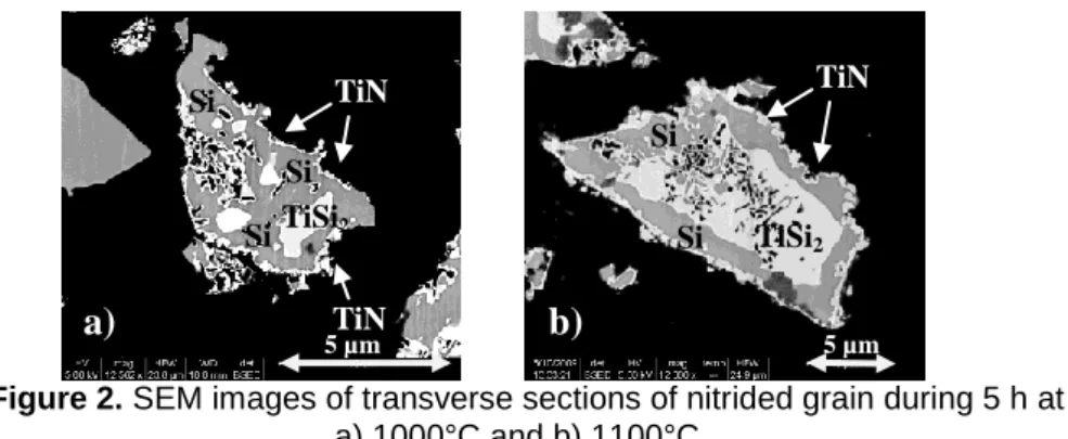
Figure 2 presentsSEM images of grain TiSi2 powder treated under nitrogen
during 5h at 1000°C and 1100°C.
The same phenomena are observed as the samples nitrited during 45 minutes. The same reaction mechanism seems to be maintained with nitridation TiSi2. Only TiSi2, TiN and Si phases are observed, with XRD
patterns and EDX analysis of Si/Ti/N. The presence of crystallized Si3N4 is
not shown through XRD patterns. A thick film is identified as TiN surrounds the grain. SEM shows that the TiN thickness is around 60 nm. TiN is also located along the porosity surface inside the grain. The silicon is located at the grain periphery, between the TiSi2 (observed by SEM in the center) and
the TiN. Free silicon embeds TiSi2 and is respectively covered by TiN layer.
Only the 3 µm in diameter grain would completely react with nitrogen according to the reaction 1.
The porosity of grains increases with the nitridation temperature and with duration of thermal treatment, as it was shown on the figure 1 and 2, nitrited
TiSi2 Si Si Si Si TiN TiN
a)
TiSi2 Si Si Si Si TiN TiNb)
5 µm 10 µm45 min and 5h respectively. The reaction with the nitrogen is the origin of this pitting phenomenon. The hypothesis is supported by the SEM observation of the presence of TiN near to the porosity. In conclusion, the process of nitridation explored at 1000 and 1100°C during 45 min and 5 hours is in agreement with the reaction mechanism 1, and the data published [2].
Figure 2. SEM images of transverse sections of nitrided grain during 5 h at
a) 1000°C and b) 1100°C.
In order to verify the existence of the Si3N4 phase, a TiSi2 powder has been
nitrided at 1100°C during 50h. XRD confirms the presence of the TiN phase and of a slight quantity of the Si3N4 phase. Figure 3 presents transverse
sections of a TiSi2 grain observed by SEM, after a nitrogen thermal
treatment during 50h at 1100°C.
Figure 3. SEM images of a section of a grain nitrided during 50 h at 1100°C.
N O Si Ti
a
Si TiSi2b
Si TiN Si TiN TiN Si Si TiSi2a)
b)
5 µm 5 µm Si3N4 Si TiN TiSi2The kinetic of transformation of free silicon in Si3N4 is very low. The volume
expansion of TiSi2 powder during nitridation is also checked through this
experiment. TiSi2 may be used to avoid skrinkage during pyrolysis of
polymer when nitridation is done in the same time.
In over work, it has been shown that a close nanoscale size of grains, the formation of Si3N4 occurs earlier at the same low temperature
[16-17]
.
Oxidation behavior
TiSi2 powder, nitrided at 1100°C during 5 hours, has been studied in order to
understand the oxidation behavior. This study is realized in-situ using the SEM during 10 minutes, at 900°C, at 140 Pa, under a O2 gas flow rate equal
to 10 sccm.
Figure 4. SEM images of a TiSi2 grain nitrided during 50 hours at 1100°C (a)
and after an in-situ oxidation at 900°C during 10 minutes (b-c). During oxidation of nitrided TiSi2, nanograins of TiN and free Si are oxidized
in TiO2 and SiO2 (figure 4). SiO2 is an amorphous phase, whereas TiO2 is in
the crystallise rutile phase. This latter phase is present as constituted of nanograins with 500nm of diameter (figure 4-c).
Conclusions
The nitridation of a micrometer-sized TiSi2 powder is reported in this paper at
1000°C and 1100°C for various times. Nanograins of TiN and free silicon are formed in the presence of nitrogen. We demonstrate that it is possible to grow Si3N4 at 1100°C, for long times of nitridation. TiN formation takes place
before the formation of Si3N4. An in-situ oxidation study by SEM of nitrided
TiSi2 shows the growth of TiO2 nanograins and of SiO2 amorphous phase.
Acknowledgements
This work was supported by the French national project NaCoMat.
Si
TiO
2Si
TiN
SiO
2TiO
2ZOOM
a)
b)
c)
40 µm 20 µm 2 µmReferences
1. D. Vojtech, B. Bartova, T. Kubatik, Mater.Sc.Engin. 2003, A361, 50 - 57 2. J.M. Cordoba, M.D. Alcala, M.J. Sayagues, M.A. Aviles, C. Real, F.J.
Gotor, Intermetallics, 2008, 16, 948 - 954
3. J.M.E. Harper, C. Cabral, C. Lavoie, Annu.Rev.Mater.Sci. 2000, 30, 523 - 543
4. R.W. Mann, L.A. Clevenger, P.D. Agnello, F.R. White, J.Res.Dev. 1995, 39, 403 - 417
5. P. Greil, J.Am.Ceram.Soc., 1995, 78 [4], 835 - 848 6. P. Greil, J.Eur.Ceram.Soc., 1998, 18 [13], 1905 - 1914
7. D. Suttor, T. Ernby, and P. Greil, J.Am.Ceram.Soc., 1997, 80 [7], 1831 - 1840
8. P. Greil, Mat.Chem.Phys., 1999, 61 [1], 64 - 68
9. P. Greil, Handbook of Advanced Ceramics, 2003, 369-390
10. T. Erny, M. Seibold, O. Jarchow, P. Greil, J. Am. Ceram. Soc., 1993, 76(1), 207-213.
11. D. Suttor, T. Ernby, P. Greil, J. Am. Ceram. Soc., 1997, 80(7), 1831-1840.
12. H.D. Akkas, M.L. Oveçoglu, M. Tanoglu, J. Eur. Ceram. Soc., 2006, 26(15), 3441-3449.
13. Z. Xie, S. Wang, Z. Chen, J. Inorg. Organomet. Pol. Mat., 2006, 16 (1), 69-81.
14. M. Ade, J. Hausselt, J. Eur. Ceram. Soc., 2003, 23(11), 1979-1986. 15. J.D. Torrey , R.K. Bordia, C.H. Henager Jr, Y. Blum, Y.Shin, W.D.
Samuels, J. Mater. Sci., 2006, 41, 4617 - 4622
16. S. Le Ber, L. Maillé, F. Rebillat, M.-A. Dourges, P. Weisbecker, C. Picard, R. Pailler, HTCMC7 Proceedings, 2010.
17. S. Le Ber, M.-A. Dourges, L. Maillé, R. Pailler, A. Guette, 8th Pac Rim proceedings 2009,
will be published into Ceramic Transactions available
in early 2010.
18. S. Sambasivan, W.T. Petuskey, J Mater. Res. 1994, 9, 2362 - 2369. 19. M. Paulasto, J.K. Kivilahti, F.J.J. Van Loo, J. Appl. Phys. 1995, 77, 4412
- 4416.