June 2010
Plasma Science and Fusion Center
Massachusetts Institute of Technology
Cambridge MA 02139 USA
This work was supported by the U.S. Department of Energy, Grant No.
DE-FG02-98ER54458. Reproduction, translation, publication, use and disposal, in whole or in part,
by or for the United States government is permitted.
PSFC/RR-10-6
Characterization of low-frequency density fluctuations
in dipole-confined laboratory plasmas
CHARACTERIZATION OF LOW-FREQUENCY
DENSITY FLUCTUATIONS IN DIPOLE-CONFIl'
W5CHUSETTS INSTI E
LABORATORY PLASMAS
OFTECHNOLOyBy
DEC 092010
JENNIFER L. ELLSWORTH
LIBRARIES
B.A., Mathematical and Physical Siouces, Wells College (2002)
B.S., Applied Mathematics, Coli uubia University (2002)
ARCHVS
S.M., Nuclear Engiiieeing, MIT (2004)
SUBMITTED TO THE DEPARTMENT OF NUCLEAR SCIENCE AND
ENGINEERING
IN PARTIAL FULFILLMENT OF THE REQ(UIREMENTS FOR THE DEGREE
OF
DOCTOR OF PHILOSOPHY IN NUCLEAR SCIENCE AND ENGINEERING
AT THIE
MASSACHUSETTS INSTITUTE OF TECHNOLOGY
June 2010
@
Massachusetts Institute of Technology 2010. All rights reserved.
A uthor ... . . . . ... ... ...
Departimi
itof Nuclear Science and Engineering
May 19, 2010
Certified by..
Jay IKesner
Senior Research Scientist
-7 esi Supervisor
Certified by.
...
Darren T. Gariner
R slearchi Scientist, Cohunbia University
7\T1Pesis
SupervisorCertified by
...
Ron aki u. rauisu
Professor Nucle6 Sci nCe ainngineering
Reader
Accepted by ...
....
...
...
/
~'
Jacquelyn C. Yanch
Professor, Nuclear Science and Engineering
Chair, Departnient. Conunittee on Graduate Students
Characterization of low-frequency density fluctuations in dipole-confined
laboratory plasmas
by
Jennifer L. Ellsworth
Submitted to the Department of Nuclear Science and Engineering on May 21, 2010, in partial fulfillment of the
requirements for the degree of
Doctor of Philosophy In Nuclear Science and Engineering
Abstract
Low-frequency fluctuations of plasma density, floating potential, ion saturation current, vis-ible light intensity, and edge magnetic field are routinely observed in the Levitated Dipole Experiment (LDX). For the purposes of this thesis, we define low-frequency as W
<<
Wbe where Wbe is the electron bounce frequency. These fluctuations in a laboratory dipole con-fined plasma lead to turbulence mixing that maintain peaked density profiles. The relation-ship between the different types of low-frequency fluctuations and plasma density transport is considered.Two 16-channel photodiode arrays were designed and constructed to study the spatial and temporal structure of these fluctuations as part of this dissertation. In addition to the photodiode arrays, a four-channel microwave interferometer is used to estimate the density profile and to measure density fluctuations in the plasma. Several electrostatic probes, including a 24-channel floating probe array, measure fluctuations at the plasma edge and eight Mirnov coils measure magnetic fluctuations.
The fluctuations fall into three general categories: broadband, turbulent fluctuations observed during nearly all plasma conditions; quasi-coherent fluctuations with low azimuthal mode numbers and peak frequencies on the order 1 kHz observed during discharges with low neutral pressure; and coherent fluctuations with zero toroidal mode number and peak frequencies on the order of 100 Hz, observed during discharges with moderate neutral fueling. The relationship between time-averaged fluctuation characteristics and plasma parameters are explored. The spatial structure of the fluctuations for several representative shots are discussed.
The turbulent fluctuations and concurrent density profiles are compared to quasilin-ear diffusion of interchange mixing in dipolar plasmas for cases where the fluctuations are random. I show that the quasilinear diffusion equation agrees well with the experimental observations of random fluctuations, supporting the conclusion that interchange mixing is causing inward transport that results in peaked density profiles. For other cases, where non-linear effects appear to dominate the plasma dynamics, the saturated fluctuation amplitudes are compared to the plasma density profiles.
Thesis Supervisor: Jay Kesner Title: Senior Research Scientist Thesis Supervisor: Darren T. Garnier
Acknowledgments
I would especially like to thank my thesis advisers Jay Kesner and Darren Garnier, whose support and guidance has meant so much to me; and to the current and former members of the LDX team for their encouragement, advice, and hard work. Jay is always willing to answer a questions, discuss and idea, or read a draft. Darren has advised me on diag-nostic design, data collection, and data analysis techniques. I am also grateful to him for introducing me to sailboat racing. Mike Mauel has inspired me with his seemingly end-less enthusiasm and we have had many helpful discussion about data analysis and plasma physics. I thank Ishtak Karim, Eugenio Ortiz, Alex Boxer, Brian Kardon, Matt Davis, Emmanuel Mimoun, and Ryan Bergmann, who were each fellow students with me at one time. John O'Brien and Susannah Brown both worked with me as UROP students and provided valuable assistance. I thank Rick Lations, Don Strahan, Alex Zhukovsky and Phil Michael for their time and expertise keeping the LDX experiment running smoothly.
I would also like to thank my thesis committee Ron Parker, Anne White, and Jeff Freidberg for their time and for their reviews of my work.
I am indebted to many other people who have assisted me during my time at MIT. Thank you to Vincent Tang and Natalia Krashenikova, with whom I shared an office when I first arrived, for making me feel welcome. I thank Rachael McDermott for loaning me the lamps for the spectrometer calibration and for showing me how to use them. Catherine Fiore and Bill McCarthy have provided valuable assistance with safety issues. I am grateful to Andrea Schmitt for her friendship.
On a personal level, I would especially like to thank my husband, Michael Hohensee for his love and support. I thank my son, Friedrich for being so agreeable about my research commitments and for not coloring in my lab notebooks. I would like to thank my mother for her unwavering confidence in me and for the hundreds of hours of free babysitting she
Contents
1 Introduction 21
2 The Levitated Dipole Experiment 25
2.1 The dipole fusion concept ... ... 25
2.2 Experimental configuration . . . . 26
2.2.1 Magnetic configuration . . . . 26
2.2.2 Heating sources . . . . 29
2.2.3 Fueling sources . . . . 31
2.2.4 Plasma diagnostics . . . . 31
2.3 Comparison of LDX to other laboratory confined dipole plasma experiments 33 2.4 What is known about LDX plasmas . . . . 34
2.4.1 Theoretical predictions of low-frequency instabilities in dipolar plasmas 39 2.4.2 Low frequency fluctuations are observed in LDX . . . . 41
3 Visible Spectrometer Measurements 43 3.1 Typical Spectra . . . . 44
3.2 Vacuum Conditioning . . . . 46
3.3 Electron temperature measurements from helium line ratios . . . . 47
3.4 Sum m ary . . . . 52
4 Fluctuation Diagnostics and Methods 53 4.1 The photodiode array diagnostic . . . . 55
4.1.1 Specifications . . . . 55
4.1.2 Diagnostic Views . . . . 60
4.1.4 The relationship between visible light intensity and chord-averaged plasm a density . . . .
4.1.5 The assumption of axi-symmetry . . . . Fast framing cameras . . . . Microwave interferometer to measure electron density . . . . Electrostatic probes and the floating probe array . . . . Mirnov coils measure magnetic fluctuations . . . . Fluctuation Analysis . . . . 4.6.1 Short-time Fourier transform . . . . 4.6.2 Two-point method . . . . 4.6.3 Probability distribution functions and higher order mo 4.6.4 Biorthogonal decomposition . . . . 4.6.5 Chordal Abel inversion . . . . 4.6.6 Synthetic diagnostic for the photodiode array . . . . . I . . . . 65 . . . . 67 . . . . 70 . . . . 72 . . . . 74 . . . . 75 . . . . 75 . . . . 75 . . . . 77 nents . . . . 78 . . . . 78 . . . . 79 . . . . 81 5 Low frequency fluctuations of the bulk plasma
5.1 Introduction . . . . 5.1.1 Three classes of fluctuations . . . . 5.1.2 Conditions during which each class of fluctuations is observed . . . . 5.2 Properties of the quasi-coherent fluctuations . . . . 5.2.1 Neutral pressure scan experiment . . . . 5.2.2 Statistical properties of edge floating potential . . . . 5.2.3 Gas puff experiment . . . . 5.2.4 Radial variation of the quasi-coherent mode frequency . . . . 5.3 Properties of the coherent, n=0 fluctuations . . . . 5.3.1 Neutral pressure scan experiment . . . . 5.3.2 Statistical properties of edge floating potential . . . . 5.3.3 Radial and toroidal structure . . . . 5.3.4 Relationship between the coherent mode and a previously observed
fluctuation at 500 Hz . . . . 5.4 Broadband, turbulent fluctuations . . . .
4.2 4.3 4.4 4.5 4.6 85 85 85 90 91 91 94 97 99 105 108 111 112 113 114
6 On the relationship of low frequency turbulence and transport 117
6.1 Introduction . . . .. . 117
6.1.1 Plasma density profiles and stability . . . . 118
6.1.2 Overview . . . . 121
6.2 Quasilinear diffusion . . . . 122
6.2.1 Applicability of quasilinear difusion to LDX plasmas . . . . 122
6.2.2 The quasilinear diffusion equations for dipolar plasma . . . . 125
6.3 Rotational shear . . . . 130
6.4 Locally, density profiles can be steeper than the invariant profile when the quasi-coherent mode is observed . . . . 132
6.5 Locally, the plasma density exceeds the cutoff density for 2.45 GHz heating when the coherent mode is observed . . . . 133
7 Conclusions 137 A Spectrometer Calibration Data 141 B Photodiode Array Diagnostic Preamplifier Board 147 C Position Calibration of PHDA 153 C .1 M ethods . . . . 153
C.2 Measurements . . . . 156
C .3 R esults . . . . 157
List of Figures
2-1 Schematic view of LDX. . . . . 27 2-2 Equilibrium magnetic flux contours and ECRH resonance locations. . . . . 30 2-3 Line-integrated plasma density measured along three interferometer channels
versus neutral pressure for deuterium plasmas with 15 kW of multi-frequency ECRH including shots 90312025-044 and 90313001-023. . . . . 38 2-4 Plasma diamagnetism versus neutral pressure for deuterium plasmas with 15
kW of multi-frequency ECRH including shots 90312025-044 and 90313001-023. 38 2-5 Stability regions for MDH like modes and entropy modes are identified as a
function of plasma density gradient d In ne/d ln V and the ratio of the density
and temperature gradients rj. . . . . 40
3-1 Average spectrum of visible light emission for a typical deuterium plasma. . 45 3-2 Computed helium line ratios as a function electron temperature for plasma
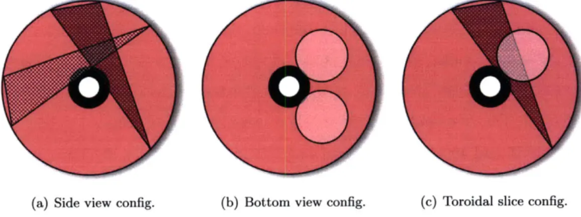
in Coronal equilibrium. . . . . 50 4-1 Fluctuation diagnostic views . . . . 54 4-2 Photodiode array diagnostic design. . . . . 57 4-3 Single channel schematic of the photodiode array preamplifier circuit. . . . 59 4-4 The photodiode array views are illustrated on a top down view of the LDX
vacuum vessel for the three configurations. . . . . 61 4-5 Comparison of the time-averaged, chord-integrated visible light intensity
measured by the photodiode arrays 1 (blue diamonds) and 2 (green trian-gles) and a monochrome video camera with a similar view (solid line). The
4-6 Comparison of plasma density profile (dashed) and visible light emission pro-file (solid) for the cases where the floating-coil is supported (shot 81218012) and levitated (shot 81217017). Both shots have identical RF heating and similar neutral pressures. The profiles have been reconstructed from time-averaged interferometer and photodiode array data during a time with 15 kW heating. . . . . 64 4-7 Visible light intensity versus the product of the neutral pressure and the
line-integrated density for deuterium discharges for deuterium discharges. The data from shots 90312025-043, 90313001-024, and 90722037-048 have been time averaged over half-second intervals when the light intensity, density and neutral pressure were steady. The ECRH configuration is held constant during the half second interval, but the data points were collected under a variety of ECRH configurations. . . . . 66 4-8 Visible light intensity versus the product of the neutral pressure and the
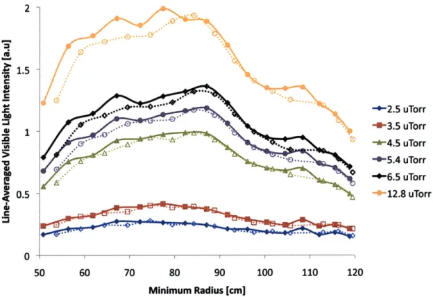
line-integrated density for deuterium plasmas with different ECRH configu-rations. The data from shots 90312025-043, 90313001-024, and 90722037-048 have been time averaged over half-second intervals when the light intensity, density and neutral pressure were steady. . . . . 68 4-9 The line-integrated light intensity measured by photodiode arrays 1 (solid)
and 2 (dashed) for 15.5 kW ECRH and different neutral pressures. The data from shots 90312037, 90313018, 90313005, 90313006, 90313012, 90313011, and 90313009 (listed in order of increasing neutral pressure) were averaged between 8 s < t < 8.5 s. . . . . 69 4-10 The line-integrated light intensity measured by photodiode arrays 1 (solid)
and 2 (dashed) averaged over half second intervals for different ECRH con-figurations and optimal neutral pressures. . . . . 71 4-11 Example of results from the synthetic diagnostic using six annular regions of
constant flux. . . . . 83 5-1 An example of quasi-coherent fluctuations measured during shot 90312041 by
the floating probe array located at the edge of the plasma near the magnetic separatrix. . . . . 87
5-2 An example of a coherent, n=0 fluctuation observed during shot 90313014. 88 5-3 An example of broadband fluctuations. The time-averaged power spectrum
of floating potential measured near the magnetic separatrix from 6 s < t <
9 s during shot 90313014 is shown for a plasma with 15 kW heating power. Most of the fluctuation activity is below 10 kHz. The fluctuation spectrum has a power law dependance at higher frequencies and two different slopes are visible. . . . . 89 5-4 This one-dimensional plot shows the neutral pressures during which the n=0,
coherent modes and n=1, quasi-coherent modes are observed during deu-terium fueled discharges with 15 kW of microwave heating. An additional column notes the values at which both modes were observed. The neutral pressure scan includes data from shots 90312025-044 and 90313001-023. . . 90 5-5 Time traces of total ECRH power, neutral gas pressure, diamagnetic flux and
line averaged density for three channels of the interferometer minimum radii, 77 cm (black solid), 86 cm (blue dashed), and 96 cm (green dotted) for shot 90313005, a representative shot from the neutral pressure scan experiment. The plasma is in a steady state from time t ~ 6 s until the ECRH is turned off. 92 5-6 Results of the neutral pressure scan experiment. The frequency, amplitude
and standard deviation of the quasi-coherent n=1 mode are shown for dis-charges during which only the n=1 mode was observed (solid diamonds) and discharges during which both the n=0 and n=1 modes were observed concur-rently (open diamonds). The data from shots 90312025-044 and 90313001-023 are time-averaged between 5 s < t < 9 s. During this time period , the plasma is heated with 15 kW of RF power from three frequencies and the plasma behavior is fairly steady state. . . . . 95 5-7 Normalized probability distribution function of floating potential near the
magnetic separatrix (solid) for shot 90313031, which has a quasi-coherent fluctuation. A Gaussian distribution with the same mean and standard de-viation is shown for comparison (dashed). . . . . 96 5-8 A large puff of D2 gas is injected into a D2 plasma between t = 7 and 8
5-9 A comparison of the time traces of total ECRH power, neutral pressure, diamagnetism, line-averaged density, and density profile peakedness for shots 90312025 (red solid) and 90312028 (black dot-dash). The three interferometer channels have minimum radii of 77 cm (solid line), 86 cm (dotted line) and 96 cm (dashed line). . . . . 101 5-10 The frequency of the quasi-coherent mode varies with radius in shot 90312028,
but not in shot 90312025. Chord-integrated, time-averaged fluctuation spec-trum measured by each of the photodiode arrays for times between 5 and 9 seconds during shots 90312025 and 90312028. Photodiode array channels are indicated by the minimum radius of the viewing chord. The fluctuation power is represented by a linear color scale. . . . . 102 5-11 Average toroidal cross-correlation between each channel of photodiode arrays
1 and 2 for shots 90312025 and 90312028 also show that the quasi-coherent mode frequency varies radially during shot 90312028. The cross-correlation data has been time-averaged between 5 and 9 seconds. . . . 103 5-12 Radial cross-correlations of photodiode array data for shot 90312028 during
5 < t < 9 seconds. ... ... 104 5-13 Normalized probability distribution functions of floating potential measured
near the magnetic separatrix are very similar for shots 90312025 and 90312028. 104
5-14 Biorthogonal decompositions of the photodiode array data for shots 90312025 (right) and 90312028 (left) show that shot 28 has additional radial structure that is apparent in topo 3. The topos are plotted for array 1 (solid) and array 2(dashed). The chronos have been Fourier transformed. . . . . 106 5-15 Time frequency domain plots of simulated photodiode array data from the
synthetic diagnostic confirm that the observed spectra in shot 90312028 is consistent with a plasma that has two spatially localized quasi-coherent modes at different frequencies, while the observed spectra in shot 90312025 is consistent with a single frequency mode that extends across the plasma. 107 5-16 Time trace of the fluctuating component of the visible light intensity
mea-sured by channel 6 of photodiode array 1 for 50 ms after time t = 7 s during shot 90313017 shows a clear oscillation at 185 Hz . . . . 108
5-17 Results of the neutral pressure scan experiment. The frequency, amplitude and standard deviation of the coherent n=0 mode are shown for discharges during which only the n=0 mode was observed (solid diamonds) and dis-charges during which both the n=0 and n=1 modes were observed concur-rently (open diamonds). The data from shots 90312025-044 and 90313001-023 are time-averaged between 5 s < t < 9 s. During this time period , the plasma is heated with 15 kW of RF power from three frequencies and the plasma behavior is fairly steady state. . . . . 110
5-18 Normalized probability distribution function of floating potential measured near the magnetic separatrix for shot 90313007, which has a coherent fluctu-ations. A Gaussian distribution with the same mean and standard deviation is shown for comparison (dashed). . . . . 111
5-19 Time-averaged fluctuation amplitude as a percentage of the visible light in-tensity for each channel of array 1 between times 6 s < t < 9 s during shot 90313017. ... ... 112
5-20 Biorthogonal decomposition of photodiode array data from 6 < t < 9 seconds for shot 90312042 which has a coherent mode with frequency 173 Hz. . . . 113
5-21 Plasma rotation frequency at the edge versus neutral pressure. The dashed line is a power law fit to the data. The data from shots 90312025-044 and 90313001-023 are time-averaged between 5 s < t < 9 s. During this time period , the plasma is heated with 15 kW of RF power from three frequencies and the plasma behavior is fairly steady state. . . . . 115
6-1 The closed system that reaches a steady state during magnetic confinement. 117
6-2 Location of the time-averaged observed density profile gradient for shot 90312011 between t = 6 and 9 seconds. Stability regions for MDH like modes and en-tropy modes are identified as a function of plasma density gradient ( =
-d ln ne/d ln V and the ratio of the temperature and density gradients q = d ln T /d ln n . . . . 119
6-3 The ratio P23 of line-averaged density from interferometer chords 2 and 3 indicates that locally, the plasma density profile is close to the invariant density profile for plasmas when the plasma diamagnetism is less than about 4 mWb. The density profile steepness increases with diamagnetism for plasmas in which the diamagnetism is high. Recall that the plasma can be unstable to either MHD modes or entropy modes even when the density profile is invariant, depending on the gradient of the temperature profile. The data from shots 90312025-044 and 90313001-023 are time-averaged between 5 s
< t < 9 s. During this time period , the plasma is heated with 15 kW of RF power from three frequencies and the plasma behavior is fairly steady state. 120
6-4 Skewness and kurtosis of the PDFs of floating potential measured near the magnetic separatrix indicate whether the plasma fluctuations are random as a function of the plasma diamagnetism. The data from shots 90312025-044 and 90313001-023 are time-averaged between 8 s < t < 8.5 s. During this time period , the plasma is heated with 15 kW of RF power from three frequencies and the plasma behavior is fairly steady state. . . . . 124
6-5 The average azimuthal electric field and the quasilinear diffusion coefficient increase with diamagnetism. They are also shown in relation to the density peakedness. The data from shots 90312025-044 and 90313001-023 are time-averaged between 5 s < t < 9 s. During this time period , the plasma is heated with 15 kW of RF power from three frequencies and the plasma behavior is fairly steady state. . . . 127
6-6 The confinement time estimated from Eq. 6.6 are shown as a function of diamagnetism. The red squares highlight the plasmas to which quasilinear theory can be applied. The data from shots 90312025-044 and 90313001-023 are time-averaged between 5 s < t < 9 s. During this time period , the plasma is heated with 15 kW of RF power from three frequencies and the plasma behavior is fairly steady state. . . . 129
6-7 The frequency of edge rotation increases with edge azimuthal electric field, but the relationship is not linear for E, > 100 V/m. The quasi-coherent mode frequency measured by the 100 cm channel of photodiode array 1 has a similar trend to the edge rotation frequency. The data from shots 90312025-044 and 90313001-023 are time-averaged between 5 s < t < 9 s. During this time period , the plasma is heated with 15 kW of RF power from three
frequencies and the plasma behavior is fairly steady state. . . . . 129
6-8 Radial profiles of azimuthal rotation rates calculated from photodiode array and probe array data. . . . . 131
6-9 Local density at three radial location (reconstructed from chordal interfer-ometer data) is shown as a function of the plasma diamagnetism. The cutoff densities for 2.45 GHz ECRH and 6.4 GHz ECRH are shown and the range of values of plasma diamagnetism during which the coherent mode is observed are indicated by shading. All values are time average between six and nine seconds during shots 90312025-43 and 90313001-23. . . . . 134
A-1 The wavelength calibration data is fit by a fourth order polynomial. . . . . 142
B-1 Photodiode array preamplifier board schematic. . . . . 149
B-2 Top side of preamplifier circuit board. . . . . 150
B-3 Bottom side of preamplifier circuit board. . . . . 151
C-1 Photodiode array calibration geometry . . . . 154
List of Tables
3.1 The excitation energies AEjj and fitting parameters A1,..., A5 for the a
sin-glet transition and a triplet transition of neutral helium [1]. . . . . 49 A. 1 Selected emission lines from various lamps used for the visible spectrometer
wavelength calibration and the spectrometer bin number at which the lines are centered. . . . .. 141 A.2 The coefficients for the fourth order polynomial that relates spectrometer
bin to wavelength are shown for the factory calibration and the our LDX calibration. . . . . 142 A.3 The spectral radiance as a function of wavelength for the labsphere used in
the spectrometer calibration. . . . . 144 A.4 Polynomial fit coefficients to the brightness as a function of bin number. . . 145 B. 1 Bill of materials. The component names for the repeated elements (R1 - R3,
C3 - C6, U1, D1) have been listed only for the first circuit, but are identical for all sixteen. In addition to the listed components, a 20 pF capacitor has been placed in parallel with R1. . . . . 152 C.1 Aperture locations for the photodiode array diagnostics are given relative
to the center of the vacuum vessel. North is 0' and up is in the positive z-direction. . . . . 155 C.2 In-vessel photodiode array calibration data. . . . . 156 C.3 The values of b, 0c and AO resulting from fitting Eq. C.8 to the calibration
data are given for each photodiode array. . . . . 157 C.4 In-vessel photodiode array calibration results. . . . . 159
Chapter 1
Introduction
Planetary magnetospheres are confined by dipolar magnetic fields and gravity. During mag-netic storms, electric fields accelerate particles inward and increase the ring current [2]. The centrifugal interchange instability is important for transport, and both inward and outward transport are observed [3]. An explanation given for this transport is that convection electric fields transport particles inwards [4].
The Levitated Dipole Experiment (LDX) was designed to study the physics of dipole plasma confinement. The relationship between plasma fluctuations and transport is an important component of this physics. The plasmas created in LDX are confined by an internal, superconducting coil. Levitating the coil eliminates the end losses to the supports and enhances confinement [5] and importantly, allows radial transport to be studied.
A dipole confined plasma can be modeled as flux tubes, where each "tube" encloses an equal amount of magnetic flux and the magnetic field lines at the surface of the flux tube are parallel to the surface of the flux tube. During a low frequency interchange instability, flux tubes move adiabatically to change places. As flux tubes move inwards, towards the dipole, the plasma is heated and compressed, while the plasma in flux tubes that move outwards expands and cools. The interchange can lead to mixing in the plasma. This instability is analogous to the Rayleigh-Taylor instability that occurs when a heavy fluid rests atop a light fluid.
In the low-frequency range (W << Wb, where Wb is the bounce frequency), dipole-confined plasmas can be unstable to MHD modes [6] and entropy modes [7], all of which are inter-change type (or flute-like) where the flux tubes move without bending or changing shape.
The frequencies of these instabilities are either zero or the low ordered diamagnetic and curvature drift frequencies, but the linear growth rates are different. The MHD modes are driven by pressure gradients or the centrifugal force, while the entropy modes are driven by density and temperature gradients. Theoretical studies [8] indicate that transport due to MHD fluctuations can be described by a quasilinear diffusion coefficient acting on the number density N in flux space, where N is the number of particles per unit flux. Whereas collisions will act to remove density gradients (particles per unit volume), fluctuations will act to remove gradients in N. Non-linear simulations have shown that these instabilities can lead to the formation of convective cells [9] and to turbulent transport [10]. In addition to instabilities, external drives such as electron cyclotron resonance heating (ECRH) can also lead to oscillatory behavior.
The idea that fluctuations can lead to peaked density profiles may seem counter-intuitive. Imagine that you have put a small pile of sand on a sheet of paper. Then you shake the paper gently back and forth. The sand will spread out, and after some time, the sand will be uniformly distributed over the surface of the paper. If you shook the paper and the sand all piled up in the middle, it would be surprising, but a similar peaking of density and pressure profiles is observed in magnetospheres and is explained by interchange mixing leading to an equal number of particles per flux tube. This density profile is called the invariant density profile and is the stationary solution to the quasi-linear diffusion equations [11]. The volume per unit flux increases with radius in a dipole plasma so in real space, the invariant density profile is highly peaked.
One would expect to see these turbulent fluctuations resulting from unstable profiles in LDX. Although linear theory predicts that the plasma will be completely stable if the pressure and density profiles are invariant to interchange motion, it is unlikely that we can create these exact profiles in the laboratory and although transport is predicted to drive the plasma towards invariant profiles, these profiles are asymptotically driven so the turbulent fluctuations would remain even when the plasma profiles are close to the invariant profiles. Thus, unsurprisingly, low-frequency fluctuations were observed during the first plasmas created in LDX using ion saturation probes at the edge, a single interferometer channel with a viewing chord that passed through the central region of the plasma, and an uncollimated photodiode that viewed a large portion of the plasma. In order to study these fluctua-tions further, I constructed a set of two photodiode array diagnostics with the purpose of
characterizing the low-frequency fluctuation activity observed in LDX and investigating the relationship between these fluctuations, external plasma controls of fueling and heating, and the later observed density profiles. In this thesis, the fluctuations are measured using two sixteen-channel photodiode arrays that have nearly identical radial views, but view from dif-ferent toroidal locations, a twenty-four channel floating probe array [12], and a four-channel microwave interferometer [13]. These are the first measurements of the characteristics of low-frequency fluctuations in a levitated dipole plasmas. This is also the first time that these fluctuations have been parameterized with respect to experimental controls.
The observed fluctuations can be separated in three categories: broadband, turbulent fluctuations, quasi-coherent fluctuations that have
f/Af
~ 5, and coherent fluctuations that havef /Af
- 100. Experiments were performed to investigate the plasma conditions under which each of these types of fluctuations were observed, and how the characteristics of the fluctuation spectra varied with plasma conditions. The toroidal and radial structure of the fluctuations were measured. The relationship between the observed fluctuations and the observed density profiles is discussed.In LDX, broadband, turbulent fluctuations are usually observed throughout the plasma. Peaked density profiles were recently observed for plasmas created with the internal coil levitated, but when the internal coil was supported (so that the field lines intersected the supports, resulting in end losses), the plasma density profiles were not peaked [14]. It was inferred that a density pinch was sustained by inward turbulent transport resulting from interchange fluctuations in the plasma. The quasilinear diffusion coefficient was calculated from floating probe measurements at the plasma edge and rate of formation of the density profile was consistent with the rate predicted by the quasilinear diffusion equation. This re-sult is extended in this thesis to consider the variation of the quasilinear diffusion coefficient (measured from an edge floating probe array) with plasma conditions.
Quasi-coherent fluctuations are observed in both the plasma core and edge during dis-charges with low levels of neutral fueling. These fluctuations have low, non-zero toroidal mode numbers and frequencies on the order of 103 Hz. In plasmas that have density profiles that are steeper than the invariant density profile, radial variation of the fluctuation spec-trum is observed. This radial variation may be evidence of rotational shear in the plasma. The quasilinear diffusion coefficients measured for plasmas with quasi-coherent fluctuations are not consistent with the observed density profiles. The probability distribution functions
of floating potential at the plasma edge indicate that these fluctuations are not random so the assumptions of quasilinear theory are not met, thus explaining the discrepancy. Non-linear effects appear to play an important role in the quasi-coherent fluctuations and they do not appear to cause transport.
Coherent fluctuations are observed in the plasma core during discharges that have mod-erate neutral fueling. These fluctuations occur at very low frequencies, on the order of 102 Hz. The measured toroidal mode number is zero. The frequency of the fluctuations does not vary radially. This fluctuation may be a breathing mode related to ECRH accessibility in the plasma.
In Chapter 2, I introduce the Levitated Dipole Experiment (LDX) and summarize what is known about LDX plasmas. In chapter 3, I show measurements of the spectrum of visible light emission from a survey spectrometer. I then use the ratios of emission from two neutral helium lines to calculate the plasma temperature. This measurement can be used in combination with an edge temperature measured from a swept probe to estimate the temperature profile in LDX. In Chapter 4, I discuss the diagnostics used to measure low frequency fluctuations in the plasma, including information on the design and calibration of the two photodiode arrays, and I also explain the mathematical methods that are used to analyze the data.
In Chapter 5, I present observations of properties of low-frequency fluctuations in the plasma including examples of broadband fluctuations, quasi-coherent fluctuations and co-herent fluctuations. I show the plasma condition during which each of the fluctuations are observed and present measurements of the toroidal and radial structure of the fluctuations. Most of the measurements that I show are average characteristics of fluctuations, so I also show an example of a gas puff experiment in which the plasma conditions are changing during the discharge and show that the behavior of the fluctuations in steady state agrees well with the behavior of the fluctations when the plasma conditions are changing. In Chapter 6, I compare the low frequency fluctuations to the observed density profiles and the quasilinear diffusion coefficient measured from the magnitude and correlation time of the edge floating potential fluctuations. I also present observations of rotational shear in the plasma by looking at the cross-correlations of toroidally separated photodiode array channels and toroidally separated probes. I summarize my conclusions in Chapter 7.
Chapter 2
The Levitated Dipole Experiment
2.1
The dipole fusion concept
The idea that plasma confined by a dipole like magnetic field might be ideal for a fusion reactor was put forth by Akira Hasegawa in 1987 [15] after doing research on planetary magnetospheres which are confined by dipolar magnetic fields. Inward diffusion and heating are observed in planetary magnetospheres during active times [16, 2]. Hasegawa's idea was to externally drive inward diffusive transport in a laboratory dipole plasma to achieve a high density in the core of the plasma.
The dipole magnetic geometry may offer some advantages as a fusion concept. The system can inherently be operated in steady state which is preferred to pulsed operation for a power plant. The internal magnets allow for excellent magnetic field utilization. Non-interlocking coils allow the floating coil to be replaced easily for servicing while maintaining high plant availability.
In addition, it may be possible to decouple the energy confinement time TE from the particle confinement time 7* which would allow the use of "advanced" fuels; in particular
a 3He-catalysed D-D [17, 18] fusion design has been proposed [19] which requires T*/TE <
2 [20]. In tokamaks [21], the particle confinement time and the energy confinement time are dominated by turbulent processes so the two times are strongly coupled [22]. In a levitated dipole device, the magnetic field is purely poloidal and the field lines are closed. Because there is no magnetic shear, field lines can interchange without breaking, making a two dimensional system where convective cells may form. At marginal stability, convective cells may transport particles without transporting any energy, thus decoupling the energy and
particle confinement times. This would be very important for a fusion reactor because it would mean that tritium and ash could be transported out of the plasma without degrading the energy confinement time.
2.2
Experimental configuration
The Levitated Dipole Experiment (LDX) has been designed to test the theory of dipole confinement and explore the dipole fusion concept. The magnets and the vacuum chamber have been designed for plasmas with marginally stable pressure profiles and densities and temperatures that are nearer to fusion grade plasmas than space plasmas. This requires a strong dipole magnet and a large vacuum chamber. The major goals of the LDX are to evaluate the confinement properties and stability of dipole confined plasmas. Plasmas in planetary magnetospheres are confined by dipolar magnetic fields so the study of plasmas confined by dipolar magnetic fields in the laboratory has applications to space physics, in addition to enhancing our knowledge of basic plasma physics and furthering the pursuit fusion energy.
The operational goals can be broken down into three phases of research. The first phase began in August 2004 when the experiment first became operational. During the first phase, hot electron plasmas were studied in plasmas created around the floating coil while it is suspended from three thin supports. During this phase of operation, we learned to operate the magnets safely and reliably while studying hot electron physics. In the second phase of operation, which began in November 2007, the floating coil has been levitated. The confinement and stability of warm, low density plasmas have been studied. The third phase of operation has not yet begun. During this phase, an ion heating source will be added so that thermal plasmas with fusion relevant densities may be studied.
2.2.1 Magnetic configuration
Plasma in the Levitated Dipole Experiment [23] is confined by a superconducting coil situ-ated in the center of a large vacuum vessel. A superconducting internal coil, or floating-coil, creates a dipole-like magnetic field that confines the plasma. The floating-coil is charged inductively in the bore of the charging-coil, then lifted to the center of the vacuum vessel with a hoist. When the floating-coil is levitated, the force of gravity is balanced by magnetic
Helmholtz
Coils
*
1 m
Floating Coll 2.45 GHzLifting Fixture 6.4 GHz
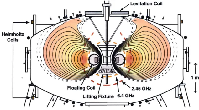
9 ii 9Figure 2-1: Schematic view of LDX. The floating-coil confines the plasma and the levitation-coil provides the upward force to counteract gravity. The black lines (solid and dashed) illustrate the flux surfaces for the vacuum field. The mechanical lifting fixture transports the floating-coil from the charging station (not shown) to the center of the vacuum vessel, then is retracted outside the closed field line region (indicated by the shaded area). The resonance locations for the 2.45 GHz and 6.4 GHz ECRH sources are also shown.
attraction to a third magnet, the levitation-coil located outside the vacuum vessel directly above the floating-coil. A schematic drawing of the experiment, Fig. 2-1, shows the location of these three magnets and the hoist. Plasmas are created by injecting neutral gas into the vacuum vessel and then ionizing and heating those particles using multi-frequency electron cyclotron resonance heating (ECRH).
The floating-coil must be levitated in order to obtain a closed field line configuration, which improves confinement by removing the losses of plasma and energy along field lines to the supports. A steady state levitating experiment is only possible with the use of a super-conducting floating-coil so that no external power supply is necessary to combat resistive power losses. The coil must operate without any external instrumentation, power lines, cooling lines, or external quench detection and protection. In addition the system requires real time feedback control to maintain levitation.
Levitation is achieved using a magnet which is placed above the floating coil so that an upward attractive force between the two coils will balance the downward gravitation forces. ... ... 1
Levitation is inherently an unstable process. A system that is levitated using an attractive force from above (as is the case for LDX) is unstable in the vertical direction. As long as the upward force is applied from far enough away, the system is stable to tilt and translation. On the other hand, a system levitated from below stable to vertical displacements, but unstable to tilts and translations. The levitation system uses eight lasers to measure the position of the floating-coil and uses a real time feedback system to adjust the current in the levitation-coil, keeping the vertical position of the floating-coil constant to within three millimeters. The limiting factor in the time the floating-coil can be levitated is the length of time that the floating-coil will remain cold enough to be superconducting: two hours if the coil will be re-cooled and re-lifted, or two and one-half hours if the coil will be discharged after the lift.
The floating-coil is made of Nb3Sn and has a maximum of current of 1.2 MA-turns [23].
When the levitation-coil is turned on, there is a slight vertical asymmetry which creates an upper ring null, as shown in Fig. 2-1. The flux surface that passes through this null point is a separatrix which divides the region of closed field lines from the region of open field lines. The separatrix passes through the magnetic mid-plane near R = 175 cm for the vacuum field, where R is the major radius measured along the magnetic mid-plane from the center of the vacuum vessel. On the inboard side, the closed field line region begins at
R = 75cm. The vacuum shell of the floating-coil extends to a maximum of R = 57.9cm,
but the vacuum shell is not shaped exactly the same as the flux surfaces, so some field lines close to coil intersect vacuum shell.
Magnetic field strength is not adjustable when the floating-coil is levitated. When the floating-coil is fully charged, the current is nearly the maximum value. If the current were reduced, then the current in the levitation-coil would need to be increased in order to sup-port the weight of the floating-coil, but the levitation-coil is already operating at maximum current. Magnetic field strength can be varied when the floating-coil is mechanically sup-ported. In addition, a pair of Helmholtz coils (shown in Fig. 2-1) are installed on the vessel to provide a vertical field. These were not operational when the data for this thesis was collected.
Initial experiments in LDX were conducted with the floating-coil supported by three thin supports. In preparation for operation with the floating-coil fully levitated, a new launching fixture was installed in the vacuum vessel (Fig. 2-1). The floating-coil rests on a lifting
fixture and is mechanically pushed to the center of the vacuum vessel prior to magnetic levitation. Plasmas can be created while the floating-coil rests on the lifting fixture, but the fixture that allowed the floating-coil to be suspended from three thin supports is not part of the new launcher. When the levitation-coil is turned on, the magnetic field structure is nearly identical to the magnetic field while the floating-coil is levitated except for the effect of the lifting fixture. For levitated operation, the lifting fixture is retracted to a position outside of the last closed flux surface.
For the purpose of this thesis, we will refer to the original configuration as suspended operation (although it was historically called supported operation) in order to distinguish it from supported operation in which the floating-coil rests on the lifting fixture. In both suspended operation and supported operation, the main source of plasma loss is to the supports, but in suspended operation, the supports intersect only a portion of the field lines, whereas in supported operation, the lifting fixture intersects all field lines. Both suspended and supported operation are essentially magnetic mirror [24] confinement schemes with the consequent particle loss cones and anisotropic plasma distribution functions. When the floating-coil is levitated (during levitated operation), the end losses are eliminated. For the most part, this thesis discusses data that was collected during levitated operation, but in some cases comparisons will be made to supported mode plasmas.
2.2.2 Heating sources
There are essentially two "knobs" for controlling the plasma parameters in LDX: electron cyclotron resonance heating (ECRH) and neutral fueling. LDX uses multi-frequency ECRH. Both the power level of each of the sources and the combination of sources that are in use are adjustable. We can choose the fuel gas which essentially determines the ion mass, and we can also adjust the neutral fueling level. Increasing the neutral fueling level has been shown to increase the plasma electron density.
Plasmas are created using multi-frequency electron cyclotron resonance heating (ECRH). A combined maximum of 16 kW at three frequencies was available at the time of these ex-periments. Two 2.45 GHz sources have maximum output power of 3 kW and 1.7 kW, respectively. The 6.4 GHz source has a maximum output power of 3 kW and the 10.5 GHz source has a maximum output power of 10 kW. The resonance locations for each frequency depend on the magnetic field strength which varies as R-3, where R is the mid-plane radius,
VacField: If = 1.1 1, = 0.282 MA t
0.0 03 1.0 13 2.0 23
Figure 2-2: Equilibrium magnetic flux contours and ECRH resonance locations. The fun-damental (thick) and second (thin) harmonics are shown for of each of the radio frequency heating sources, including 2.45 GHz (orange), 6.4 GHz (red), 10.5 GHz (orange). The upper hybrid resonance (blue) overlaps the fundamental harmonic 6.4 GHz ECRH source and the second harmonic of the upper hybrid overlaps the fundamental harmonic of the 2.45 GHz ECRH source.
so each frequency will heat the plasma at a different radial location.
Figure 2-2 illustrates the resonance locations for the fundamental and second harmonics of each of the three heating frequencies. Higher frequency sources resonate closer to the floating-coil because the magnetic field is stronger there. The upper hybrid resonance occurs in the same region as the heating resonances. The equilibrium flux contours are also shown. Notice the presence of a separatrix that divides the closed field line region from the open field line region.
Only the 2.45 GHz source has fundamental a resonance location at the mid-plane, within the closed field line region. The fundamental resonances of higher frequency sources resonate at the mid-plane on field lines that intersect parts of the floating-coil. In warm plasmas, we expect heating from the higher harmonics and broad heating profiles.
The power of each heating frequency can be varied. The combination of sources used for heating and the times at which each source turns on and off are also programmable. Each RF source can be operated for the full length of the plasma discharge. The maximum
heating duration is limited to fourteen seconds by the data system. Increased heating power results in increased plasma density.
LDX uses a cavity heating scheme for ECRH in which there is little absorption during the first pass of the waves through the vessel, but the waves reflect of the walls many times. Most of the plasma heating occurs during these subsequent passes through the plasma so the heating is as axisymmetric as possible even though the antennas are localized. The 10.5 GHz antenna is located at the bottom of the vacuum vessel and the waves are launched towards the center of the vessel. The 2.45 GHz and 6.4 GHz antennas are launched in X-mode from the side of the vacuum vessel at the north-east port [25, 26].
2.2.3 Fueling sources
Plasmas are fueled by neutral gas that is injected into the vacuum chamber through a piezoelectric valve on the south-west port. The amount of injected gas is controlled by varying the length of time that the valve is open. The fueling sequence for plasma shots has two parts, a large pre-puff that is injected before the heating is turned on and a steady low-level fueling during the discharge generated by opening the valve for short periods of time with a frequency of 100 Hz.
Both the type of gas that is injected, and the amount of fuel are adjustable. Plasmas are generally created with deuterium (H 2) gas because that is the fuel that would be used
in a dipole fusion reactor if the concept is shown to be feasible and advantageous. Hydrogen
(HI), helium, and argon gas are also available for fueling. Different fuel gasses can be used
to evaluate the dependance of ion mass on plasma phenomena.
2.2.4 Plasma diagnostics
LDX has a basic set of diagnostics to measure plasma density profiles, pressure profiles, edge characteristics and fluctuation properties. A brief overview the diagnostic systems is given here. Detailed discussion diagnostics used to measure plasma fluctuations is given in Chap-ter 4, while information about the survey spectromeChap-ter is given in ChapChap-ter 3. The survey spectrometer gives us an idea of the spectrum of visible light emitted from the plasma and the impurity content of the plasma. This diagnostic was also used to measure the electron temperature from line ratio measurements. Using this temperature measurement and an additional temperature measurement from an edge swept probe, I present the only
mea-surement of temperature profiles in LDX to date. A four-channel microwave interferometer is used to measure electron density profiles and fluctuations [13] (§4.3). A single channel reflectometer is currently being developed, but data from that diagnostic is not presented here. The neutral pressure is measured by a vacuum ion gauge. Visible light emission is strongly dependent on the neutral pressure. The plasmas in LDX are fairly low density, most of the visible light emission is the result of electron impact ionization. In addition, many other plasma parameters have been shown to trend with neutral pressure.
Magnetic pick-up coils and flux loops are used to reconstruct the equilibrium plasma pressure [27]. A total of eighteen pickup coils measure the magnetic field in the directions normal and tangential to the vacuum vessel surface at nine locations. A total of 14 flux loops are located inside and outside the vacuum vessel to measure magnetic flux in the vertical direction [28]. When data for plasma diamagnetism is presented in this thesis, it is measured by flux loop 5 which surrounds the outside of the vacuum vessel slightly above the magnetic mid-plane (z = 23cm).
Moveable electrostatic probes are used to diagnose the edge of the plasma near the magnetic separatrix (§4.4). A 24-channel floating probe array is used to measure the toroidal structure of edge fluctuations. Two ion-saturation probes can be used as a mach probe to measure plasma flow. A swept probe is used to measure edge density and temperature. To measure magnetic fluctuations, eight Mirnov coils are arrayed toroidally on the vacuum vessel at the mid-plane (§4.5).
The visible light diagnostics include two linear photodiode array cameras (§4.1) and Phantom fast cameras (§4.2). The photodiode array diagnostic is a custom design while the Phantom fast cameras are a commercial product. An H-o filtered, Sony camera collects standard monochrome video of the plasma. This camera has a larger field of view than the arrays which are only one-dimensional and the Phantom cameras which are often operated with a reduced view in favor of increased speed.
A survey spectrometer measures the intensity of light emission between 330 nm (ultra-violet) and 580 nm (yellow) with an average resolution of 1.2 angstroms. A series of spectra are collected during a plasma discharge. This diagnostic can be used to discover the impu-rity species in the plasma. We can use line ratio information to determine the time resolved density and temperature of the cool background plasma along a single chord, although the resolution of this spectrometer is not high enough to provide information about individual
line shapes.
X-rays are emitted from the plasma as a result of bremsstrahlung radiation that occurs when fast electrons collide with ions or electrons, although the electron-electron emission is much weaker than the electron-ion emission. A single channel pulse height analyzer measures the energy spectrum of x-rays in the 1-20 keV range. This information can be used to deduce an effective line-averaged electron temperature. In addition, x-ray intensity is measured along a single chord by a sodium iodide detector, which is sensitive to x-ray with energies up to 1 MeV. The x-ray intensity detector views the floating-coil so it is also sensitive to x-rays that are emitted when fast electrons collide with the floating-coil vacuum shell. This is useful for identifying when instabilities such as hot electron interchanges occur. Two single-channel radiometers measure the electron cyclotron emission from the plasma. These provide information about the fast electron population. Initial measurements of tem-perature suggest the peak fast electron temtem-perature is on the order of 100 keV for plasmas created with 15 kW of power at three frequencies [29].
2.3
Comparison of LDX to other laboratory confined dipole
plasma experiments
Plasmas in LDX are stabilized by compressibility. This is very different from the tokamak confinement scheme. LDX has been designed with a large vacuum chamber so there can be a lot of flux expansion. In this way it's very different from other current and past dipole and multipole experiments.
The Collisionless Terrella Experiment (CTX) [30] at Columbia University uses an in-ternal supported copper magnet to study hot electron plasmas confined by a dipole-like magnetic field. In such a configuration the predominant loss mechanism in the plasma is to the supports. Supported operation in LDX can be compared to the configuration of the CTX, as that experiment also uses a support which intersects all field lines. Even so, LDX is a much larger experiment than CTX. The floating-coil in LDX produces a larger magnetic field than the internal coil in CTX. The LDX floating-coil carries eight time more current than the CTX internal coil and the LDX vacuum chamber is about three times larger than the CTX vacuum chamber. CTX investigates plasmas that are relevant to space astrophysics and fusion plasmas. Important results include studies of the hot electron
interchange mode [31, 32] and characterization of turbulent fluctuations [33].
There is also a supported double dipole experiment, Magnetor, in Russia [34]. In this experiment an external magnetic field is applied to reduce the plasma volume. They find there is a good agreement between the theoretical density profile and the measured density profile. Unlike the plasmas created in LDX in levitated mode, the plasmas created in Magnetor have flat temperature profiles.
Several ring trap (RT) experiments including proto-RT, mini-RT, and RT-1 are currently underway in Japan. The largest experiment, RT-1 is about one-fifth the size of LDX. The internal coil is a high temperature superconductor that carries 250 kA of current and their vacuum chamber is 2 m in diameter [35]. The experiment was designed to investigate a self-organized state observed in Jupiter's magnetosphere during which the hydrodynamic pressure from a fast plasma flow balances the plasma's thermal pressure [36]. In addition, they are interested in studying the confinement of non-neutral plasmas in the device and have successfully obtained long confinement times [37]. All of these experiments have a smaller flux expansion than LDX.
2.4 What is known about LDX plasmas
We will briefly review the major experimental results from LDX and the outstanding ques-tions. One important goal of the LDX program is to evaluate the stability and dynamics of high-beta plasmas with energetic particles confined by dipole magnetic fields. High beta plasmas have been confined and sustained in the LDX device and peak beta of over 20% has been observed [28]. The pressure profiles of plasmas created with the floating-coil in suspended mode were highly anisotropic and the pressure is contained mostly in the fast electrons which are a small fraction of the total electron population [27]. In con-trast, the pressure profiles of plasmas confined by a levitated internal coil were much more isotropic [38] and the pressure was stored in both the fast electrons and the warm electrons, which are a much larger fraction of the electron population [5].
The biggest threat to stability observed to date is the hot electron interchange mode (HEI) which can lead to total plasma loss [39], but has been shown to be stabilized by sufficiently low hot electron fraction [40], which is easily obtained with levitated operation with its improved bulk plasma confinement. Most of the work on hot electron interchange
modes in LDX has been done on suspended mode plasmas, but HEIs have also been observed in levitated mode during extreme low density operation with low gas fueling and ideal wall conditions.
LDX is able to confine high (electron) beta plasmas for many confinement times. Lev-itation of the internal floating-coil greatly enhances plasma confinement. Plasma diamag-netism increases by a factor of two when the magnet is levitated and line-averaged plasma density increases by a factor of nearly three for similar fueling conditions. In addition, the discharges created during levitated operation are characterized by steep, centrally peaked density profiles [14].
MHD predicts that linear stability is determined by pressure profiles. Non-linear MHD predicts stationary pressure and density profiles. Kinetic theory predicts that plasmas that are marginally stable to interchange modes will be stable when they have an equal number of particles confined within each volume of equal magnetic flux or flux tube defined as
f
1 [11]. These density profiles have been observed in planetary magnetospheres and arecalled "invariant profiles" because the density profile is invariant to interchange motion [41]. They have also been called "stationary profiles" because this density profile is the time-independent solution to the quasi-linear transport equation [11]. In LDX, these profiles are also referred to as "natural" profiles because the plasma assumes these profiles without external profile control. In LDX, the invariant profiles are of the form n oc r-4 . Peak densities during levitated operation are typically on the order of 10" cm-3.
A. C. Boxer used a four-channel microwave interferometer to reconstruct the plasma density profiles in LDX under a variety of conditions. He found that when the floating-coil was levitated, density profiles were often highly peaked and approached the situation where the number of particles contained within equal volumes of magnetic flux was constant [13].
In contrast, when the floating-coil was supported, the density profiles were fairly flat. In addition, the plasma density profile has been observed to relax to the natural profile during some discharges at times when there were no changes made to the external controls [42].
We assume that these highly peaked density profiles are sustained by inward turbulent transport because the reconstructed profiles of visible light emission indicate that there is no emission near the internal coil. The visible light emission is proportional to the neutral density so we assume that there is no source of neutral particles to peak up the density profile. The motivation for this thesis is to investigate the low frequency, turbulent