Publisher’s version / Version de l'éditeur:
ACM Transactions on Graphics (TOG) - Proceedings of ACM SIGGRAPH 2005,
24, 3, pp. 869-877, 2005
READ THESE TERMS AND CONDITIONS CAREFULLY BEFORE USING THIS WEBSITE.
https://nrc-publications.canada.ca/eng/copyright
Vous avez des questions? Nous pouvons vous aider. Pour communiquer directement avec un auteur, consultez la première page de la revue dans laquelle son article a été publié afin de trouver ses coordonnées. Si vous n’arrivez pas à les repérer, communiquez avec nous à PublicationsArchive-ArchivesPublications@nrc-cnrc.gc.ca.
Questions? Contact the NRC Publications Archive team at
PublicationsArchive-ArchivesPublications@nrc-cnrc.gc.ca. If you wish to email the authors directly, please see the first page of the publication for their contact information.
NRC Publications Archive
Archives des publications du CNRC
This publication could be one of several versions: author’s original, accepted manuscript or the publisher’s version. / La version de cette publication peut être l’une des suivantes : la version prépublication de l’auteur, la version acceptée du manuscrit ou la version de l’éditeur.
For the publisher’s version, please access the DOI link below./ Pour consulter la version de l’éditeur, utilisez le lien DOI ci-dessous.
https://doi.org/10.1145/1073204.1073276
Access and use of this website and the material on it are subject to the Terms and Conditions set forth at
GoLD : interactive display of huge colored and textured models
Borgeat, Louis; Godin, Guy; Blais, François; Massicotte, Philippe; Lahanier,
Christian
https://publications-cnrc.canada.ca/fra/droits
L’accès à ce site Web et l’utilisation de son contenu sont assujettis aux conditions présentées dans le site LISEZ CES CONDITIONS ATTENTIVEMENT AVANT D’UTILISER CE SITE WEB.
NRC Publications Record / Notice d'Archives des publications de CNRC:
https://nrc-publications.canada.ca/eng/view/object/?id=a66d0c87-7b13-478b-81d5-e57573ab0e79
https://publications-cnrc.canada.ca/fra/voir/objet/?id=a66d0c87-7b13-478b-81d5-e57573ab0e79
National Research Council Canada Institute for Information Technology Conseil national de recherches Canada Institut de technologie de l'information
GoLD: Interactive Display of Huge Colored and
Textured Models *
Borgeat, L., Godin, G., Blais, F., Massicotte, P., and Lahanier, C.
August 2005
* published in The Association for Computing Machinery (ACM) Transactions on Graphics
(Proceedings of ACM SIGGRAPH 2005). July 31 - August 4, 2005. Los Angeles,
California, USA. NRC 48126.
Copyright 2005 by
National Research Council of Canada
Permission is granted to quote short excerpts and to reproduce figures and tables from this report, provided that the source of such material is fully acknowledged.
GoLD: Interactive Display of Huge Colored and Textured Models
Louis Borgeat Guy Godin Franc¸ois Blais Philippe Massicotte∗
National Research Council of Canada
Christian Lahanier† C2RMF
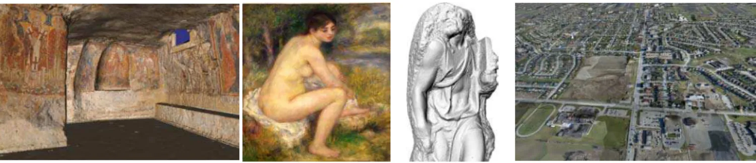
Figure 1: GoLD can display both highly tesselated models and highly textured models at low or high resolution. These example models are rendered at interactive rates. From left to right: a Byzantine crypt, a painting by Renoir (250M triangles, one day of scanning); Stanford’s model of Michelangelo’s St. Matthew (372 M triangles), and a terrain from aerial surveying built from over 100 million data points and 6800 4M-pixel digital photographs.
Abstract
This paper presents a new technique for fast, view-dependent, real-time visualization of large multiresolution geometric models with color or texture information. This method uses geomorphing to smoothly interpolate between geometric patches composing a hi-erarchical level-of-detail structure, and to maintain seamless conti-nuity between neighboring patches of the model. It combines the advantages of view-dependent rendering with numerous additional features: the high performance rendering associated with static pre-optimized geometry, the capability to display at both low and high resolution with minimal artefacts, and a low CPU usage since all the geomorphing is done on the GPU. Furthermore, the hierarchical subdivision of the model into a tree structure can be accomplished according to any spatial or topological criteria. This property is particularly useful in dealing with models with high resolution tex-tures derived from digital photographs. Results are presented for both highly tesselated models (372 million triangles), and for mod-els which also contain large quantities of texture (200 million tri-angles + 20 GB of compressed texture). The method also incorpo-rates asynchronous out-of-core model management. Performances obtained on commodity hardware are in the range of 50 million geomorphed triangles/second for a benchmark model such as Stan-ford’s St. Matthew dataset.
CR Categories: I.3.3 [Computer Graphics]: Picture/Image Generation—Viewing algorithms; I.3.5 [Computer Graphics]: Computational Geometry and object modeling—Geometric algo-rithms, Object hierarchies
Keywords: Visualization, multi-resolution geometric modeling,
∗e-mail: firstname.lastname@nrc-cnrc.gc.ca †
e-mail: christian.lahanier@culture.gouv.fr
view-dependent rendering, out-of-core rendering, level-of-detail, geomorphing, texture mapping
1
Introduction
While models composed of a few million polygons were considered as very large only a few years ago, current sensor-based modeling techniques can gather enough information in a period of a few days to construct models of hundreds of millions of primitives, with gi-gabytes of texture information. Interactive display of such models on commodity hardware requires the use of view-dependent multi-resolution techniques that can handle the out-of-core management of those large datasets or provide sufficient compression to main-tain them in-core. Design goals for such methods include maxi-mum rendering speed, adaptivity to various types of models, and the capacity to avoid rendering artefacts associated with the view-adaptive real-time transformation of the displayed dataset. This paper introduces a new view-adaptive multi-resolution display method called GoLD (for Geomorphing of Levels of Detail). Tri-angular mesh models are first decomposed into a hierarchical level of detail (LOD) tree structure where each leaf node is a patch of geometry segmented from the original model; smooth continuous geomorphing is applied between patches while maintaining global continuity over the entire model during interactive navigation. The method can be applied to both colored (color-per-vertex) and high-resolution textured models of objects and scenes, and can render the models at interactive rates with minimal visual artefacts at both high and low resolution.
The GoLD method combines the following major advantages:
• Static pre-optimized geometry for high performance
render-ing. We use vertex-cache optimized strips as the primitives of our view-dependent computations, resulting in a better balance between GPU and CPU usage [Borgeat et al. 2003; Cignoni et al. 2004]. Our method allows rendering of up to 50 million geomorphed triangles per second on a GeForce 6800 GPU for models such as the St. Matthew in Figure 1.
• The absence of visual artefacts provided by geomorphing. One inconvenient of LOD based techniques is the “popping”
To appear in the ACM SIGGRAPH conference proceedings
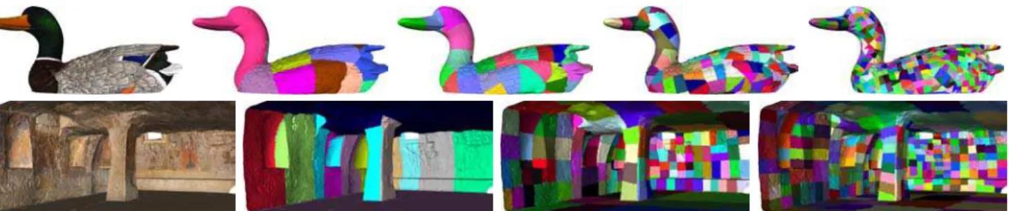
Figure 2: Result of the recursive segmentation for two types of models. Top: Color-per-vertex model of a duck carving. The model is recursively segmented in geometric space to produce more compact groups. Bottom: This model of a crypt contains much more texture than geometry. It is first segmented so that each group corresponds to only one original digital photograph. The groups are then re-segmented in texture parameterization space so that geometry groups map into rectangular subsets of similar size in the original image.
effect that occurs at changes in resolution levels. Even when rendering at high resolution, LOD switching can still create a noticeable visual artefact, potentially forcing an increase in resolution that is not needed to improve image quality but as a way to hide artefacts. It had been noted previously [Hoppe 1998; Lindstrom and Pascucci 2002] that errors as large as a few pixels can go unnoticed if geomorphing is used to avoid abrupt temporal transition artefacts. Smooth appearance can then be obtained at lower geometric resolutions. This prop-erty extends the method to more applications where all the resources cannot be invested in high resolution rendering.
• Application-adaptive pre-processing. The method can be adapted in order to optimize its pre-processing for different types of models, including taking into account existing parti-tions of the original dataset. This feature is particularly ad-vantageous in the case of models with large quantities of high resolution textures, such as those obtained from mapping dig-ital photographs. The method avoids the need for techniques that might become issues for an enormous dataset, such as the generation of texture atlases, the use of multitexturing, or reparameterization. With GoLD, geometric models can be partitioned into a hierarchy of patches that respect the bound-aries of individual texture images, and where the shape of the patches is optimized for compactness in texture space. Con-sequently, the original texture images can be directly used without any resampling to build a simple and minimal-sized hierarchical texture tree used for paging and rendering. Fur-thermore, the method can be naturally extended to optimize for criteria such as surface orientation or occlusion culling for complex models, and to take into account heterogeneous mod-els with parts characterized by different attribute types.
• Access to the original model at full resolution. For many vi-sualization applications, it is important to be able to differen-tiate with good certainty real features from artefacts caused by the pre-processing or by the rendering. At full resolution, the original geometric model and unaltered original texture images are directly rendered.
• Minimal dependency on frame-to-frame coherency. Our im-plementation performs pre-fetching and decompression of out-of-core data in a separate thread, thus minimizing impact on the frame rate. The amount of computations to be executed in the main thread is otherwise independent of any change in the viewpoint besides the direct upload of new vertex data to the GPU.
• Limited CPU usage. All geomorphing interpolations are com-puted on the GPU by a vertex program, and the real-time data structure is mostly static.
1.1 Overview of the Method
During pre-processing, the triangular mesh model is converted into a LOD hierarchy of optimized geometry patches and associated tex-ture or attribute data. The first step of this preprocessing is to sim-plify the entire model into a sequence of discrete LODs using an algorithm based on vertex aggregation. The lowest resolution LOD is decomposed into a set of triangle patches. The next higher reso-lution level is then partitioned along the same boundaries, and each group in this level is subpartitioned until the desired granularity is reached. This process is applied in sequence to all levels of the model, resulting in a hierarchy of group subdivisions spanning the whole sequence of LODs (see Figure 2). Groups can be shaped ac-cording to criteria such as compactness, common orientation, tex-ture/viewpoint association, culling requirements, model structure, existing partitions, and number of primitives per group. Groups are individually converted into vertex-cache optimized triangle strips in order to maximize rendering speed. These groups or patches con-stitute the basic units for all the view-dependent computations. At run time, a front in the LOD patch hierarchy is selected during the culling process. Geomorphing ratios between selected groups and their lower resolution parent are computed for each frame. Seamless continuity between neighboring LOD groups is main-tained at all time by geomorphing boundary points between groups according to a specific set of rules while the other points are mor-phed using a uniform ratio per individual patch. The geomorphing is actually performed by a vertex program on the graphics process-ing unit (GPU), leavprocess-ing more CPU resources available for render-ing or other tasks. Geomorphrender-ing is applied to space and texture coordinates, normals and colors. Out-of-core pre-fetching is done asynchronously on a different thread to minimize effects on navi-gation.
The patches produced by the recursive segmentation are the basic primitives for the view-dependent computations, the culling, the rendering and the paging. The chosen segmentation criteria used to create the patches can therefore significantly affect the display per-formance. The proposed framework can accommodate any combi-nation of spatial or topological criteria to produce the group struc-ture. This high flexibility broadens the application scope of the technique, as we will demonstrate for the particular case of large textured models.
2
Related Work
Solutions to accelerate the rendering of large models are well es-tablished in computer graphics (e.g. [Clark 1976; Funkhouser and
S´equin 1993]). Visualization techniques for large models must typ-ically address two key problems: view-dependent adaptation of the model resolution, and efficient occlusion culling. However, the rel-ative importance and efficiency of these two tasks depend on the type of model: sensor-derived models are usually composed of a relatively small number of highly tesselated triangular mesh sur-faces, requiring mostly resolution adaptation, while CAD/synthetic models often contain a large number of geometric components of lower polygon count, benefiting mostly from efficient culling tech-niques. The work presented here, even if well adapted to the im-plementation of culling solutions, addresses mainly the problem of real-time resolution adaptation for large mesh models.
Many different approaches for the interactive visualization of large models of objects or scenes have been proposed in recent years. An important family of techniques is based on the concept of vertex hi-erarchies: typical examples include [Hoppe 1997] or more recently [El-Sana and Bachmat 2002]. Such methods have the advantage of bringing the view-dependent computations to the individual ver-tex/triangle level, thus providing the possibility of creating a near-optimal geometry subset for each generated frame. Other methods expand classic LOD methods to the visualization of large models by creating hierarchical LOD structures [Erikson et al. 2001]. More recently [Cignoni et al. 2004] has proposed an algorithm that pro-duces a regular tetrahedral subdivision LOD hierarchy structured to maintain connectivity between rendered patches.
An alternative approach for fine-grained view-dependent render-ing of large models is point-based techniques [Rusinkiewicz and Levoy 2000]. These methods allow for simple and efficient view-dependent computations, very compact representation of the model, and offer a high rendering rate [Dachsbacher et al. 2003]. Initial re-sults showed that these techniques tended to produce significantly more visual artefacts than triangle based methods, but recent results demonstrated that high quality images can also be obtained, how-ever at the overhead cost of complex filtering techniques [Zwicker et al. 2004].
With the rapid expansion of rendering capabilities of GPUs, many techniques based on fine-grained view-dependent computations have become significantly CPU bound. Work has been done to pro-duce methods that would repro-duce the load on the CPU and better exploit the faster GPUs by coarsening the granularity of the view-dependent rendering. On current graphics hardware, the selection of geometry patches instead of points/polygons as the finest level of decomposition yields significant performance gains. First, the geometry can be cached on the GPU memory, thus reducing band-width requirements [Levenberg 2002]. Additionally, recent tech-niques propose the use of pre-optimized patches of geometry as the basis for the view-dependent computation [Borgeat et al. 2003; Cignoni et al. 2003a; Cignoni et al. 2004]: the triangles composing a patch are converted into strips and reordered to take advantage of the vertex cache.
Techniques that operate at a coarser granularity for the view-dependent computations bear the risk of creating more artefacts since the viewed geometry will change less often but in a more significant manner, thus causing effects such as popping and vis-ible frontiers between neighboring groups at different resolutions. Even the fine grained methods can produce noticeable artefacts as geometry undergoes transformation. Geomorphing has been pro-posed to hide transitional artefacts and consequently improve the visual quality when rendering with view-dependent techniques. Its usage is well established for terrain visualization applications [Fer-guson et al. 1990] and is still an integral part of many methods such as [Hoppe 1998; Duchaineau et al. 1997; Lindstrom and Pascucci 2002]. For objects and non-terrain scenes, geomorphing was intro-duced as part of progressive meshes [Hoppe 1996; Hoppe 1997]. It
has since been applied to many other view-dependent algorithms, based either on vertex hierarchies [Grabner 2001], or on different simplification approaches such as wavelets [Azuma et al. 2003]. More recently, a proof of concept for the geomorphing of an opti-mized geometric patch hierarchy was presented in [Borgeat et al. 2003]. Nonetheless, the use of geomorphing in the general 3D sur-face case is still less widespread than for terrain applications. The out-of-core management of large texture databases for view dependent rendering has also received significant attention. Tree structures similar to the ones used to represent geometry are usu-ally applied [D¨ollner et al. 2000; Cignoni et al. 2003a]. In [Hwa et al. 2004], the authors proposed a new texture representation that reduces the necessity of blending the textures between levels of de-tail. More advanced perceptual metrics [Dumont et al. 2001] re-sulted in improved paging performance. Hardware solutions have also been proposed, such as SGI’s clip textures approach [Tanner et al. 1998] that creates virtual mipmaps from enormous texture images that abstract the out-of-core management of texture from the scene graph management.
Many techniques have focused on the problem of simplifying and afterwards accessing meshes that exceed the size of main memory. The approaches for simplification vary from segmenting the model before simplifying it [Hoppe 1998], to restructuring the data so that it can be maintained and accessed efficiently using the OS paging system or a custom scheme [Cignoni et al. 2003b; Lindstrom and Pascucci 2002]. Other techniques choose to stream the data pro-gressively in main memory [Isenburg et al. 2003]. In [Isenburg and Gumhold 2003] the model is efficiently compressed so it can be fitted entirely in main memory. We refer the reader to [Isenburg et al. 2003; Cignoni et al. 2003b] for recent reviews and classifi-cations of the various techniques available for efficient out-of-core processing.
3
Preprocessing
An interesting feature of our approach is that there are relatively few constraints on the choice of methods used for the simplification and segmentation of the model. In this section we first describe the required steps and minimal constraints associated with the prepro-cessing, we then discuss the segmentation issues associated with patch-based rendering, and we finally describe the implementation used to produce the results presented in this paper.
3.1 Requirements
The first step of the preprocessing is to construct a sequence of levels of detail from the original mesh model. Any simplifica-tion criterion can be applied, as long as the method is based on merging vertices, such as vertex/edge collapse or vertex clustering techniques. Methods based on vertex removal are less appropriate since they do not provide a natural path for geomorphing to oc-cur between LODs. By simplifying before segmentation, we avoid all constraints related to maintaining coherent boundaries between neighboring patches during the simplification process. As we sim-plify the model, we must retain the vertex aggregation history be-tween the levels since they will constitute the geomorphing paths during rendering.
The second step consists of the recursive segmentation of the model within the created sequence of levels of detail. This task is achieved by first segmenting the lowest resolution level of detail into a set of patches of the desired shape and size/granularity. Then, the next higher resolution level is segmented along the same boundaries by
To appear in the ACM SIGGRAPH conference proceedings
Figure 3: Group subdivision in texture space. Left: contour of the geometry associated with this image. Right: generated hierarchy of rectangular texture units.
following the vertex aggregation paths kept from the original sim-plification. Each subgroup of this higher resolution level is again segmented according to a similar or new criterion until the desired granularity is achieved. This process is repeated recursively up to the full resolution original model. Figure 2 illustrates the resulting patch hierarchy obtained with our implementation for two different models.
As the groups are being segmented, we must also maintain neighboring information between boundary points of the adjacent patches. This information is needed by the real-time algorithm to insure global continuity over the whole model during interactive visualization. After the segmentation, each patch is individually converted into a single triangle strip, and its vertices are reordered for maximal use of the graphics card’s vertex cache. The tree struc-ture, culling data, model-space error values, and group geometry including neighboring and destination information are finally en-coded into a disk file representation.
3.2 Segmentation
The pre-processing transforms the model into a group hierarchy composed of triangle patches: these patches form the basic unit for paging, culling, rendering and all view-dependent computations. The behavior of the segmentation can have a significant impact on the quality and performance of the visualization. More compact patches will mean smaller bounding volumes and therefore more precise view-dependent computations. Patches with more uniform orientation will lead to efficient orientation culling. Patches of uni-form memory size will lead to smoother and more predictable pag-ing performance, etc. The actual optimal segmentation criteria are likely to vary significantly from one context to another.
For non-textured models with a simple topology such as the St-Matthew dataset or the Renoir painting of Figure 1, a segmentation that does not take into account the actual shape or other surface features may still yield acceptable results. Examples of recursive spatial segmentation include octree-based subdivision or the tetra-hedral subdivision that is at the base of the adaptive tetrapuzzles method [Cignoni et al. 2004]. However, these techniques can poten-tially divide surfaces along worst-case axes, creating long and com-plex boundaries between the groups. Additionally, more serious
is-sues will arise when we try to address the case of more complex or heterogeneous models. For a model composed of separate parts, different texture images, or areas associated with different shading programs, it is preferable to respect these natural boundaries in the initial segmentation, thus resulting in the construction of homoge-neous groups that will be more efficiently rendered. Another case is the creation of synthetic textures for applications such as normal mapping that could require a segmentation capable of producing patches with a disk topology for parameterization purposes. For complex models that would benefit from occlusion culling, the seg-mentation should be able to assign naturally occluding parts to sep-arate group. This paper does not aim at providing innovative seg-mentation solutions for each category of models, but rather presents a framework that can be easily adapted to these different applica-tion contexts by integrating appropriate segmentaapplica-tion methods. We have implemented two different segmentation strategies for produc-ing the results in the paper: one for non-textured models built from 3D sensor data, and one for texture-mapped models made from 3D sensor data and digital photographs containing more texture than geometry information. We will describe both approaches to illus-trate the importance of adapting the segmentation to the model type.
In the simpler case of the color-per-vertex models, we have cho-sen to segment the models with the goal of maximizing only for compactness. We applied a principal component analysis technique similar to [Yoon et al. 2003]. The presence of sensor noise in the data and of features at many resolution scales makes orientation culling relatively inefficient on such model, so we did not take sur-face orientation into account during segmentation. We recursively subdivided the groups by computing the axis of maximum variation and split the model in two segments of equal length along that axis. This rule aimed at producing groups with smaller bounding spheres and therefore making more precise the view-dependent computa-tions.
Models created by combining 3D active sensors and digital cam-eras often contain significantly more texture than geometry. This is the case with the two textured models presented in the paper, and will be in many digitized surface visualization applications. The bottleneck in processing and visualizing such models lies mostly in the management of the texture information. In the case of the crypt illustrated in Figure 2, the lowest resolution level of the model was first segmented manually in an editing software, creating a group of geometry associated with each digital photograph (Figure 3, left). The group boundaries were adjusted in order to minimize visible transitions due to imperfect color adjustments between the pho-tographs, and to select the best available texture in overlapping areas. This first segmentation was provided to the pre-processing software. Then, the model was simplified with the added constraint that points bordering that initial segmentation would not move out of their original texture. Each group was then recursively divided, not in 3D space but instead in the texture parameterization space (Figure 3, right). We have implemented a heuristic method that quickly evaluates all possible axis-aligned cuts in texture space to find a solution that optimizes simultaneously for three criteria: min-imal texture area, similar texture size and squareness of the two gen-erated textures. It also takes into account the necessity of scaling up to the nearest power of two for older GPUs. This segmentation approach leads to the following gains: original photographs are pre-processed independently, the resulting texture tree for paging is of minimal size, and less texture must be stored on the GPU at any given time. We handled the case of the large landscape model of Figure 1 in a similar manner, except that the initial segmentation associating digital photographs to geometry groups was computed automatically based on the distance to the image center in texture space.
3.3 Implementation
For the simplification phase, we have used the well known “Quadric with attributes” method proposed by [Garland and Heckbert 1998], combined with a simple parallelization scheme. We take as input an indexed triangular mesh with attributes, and if available, tex-ture data including textex-ture coordinates or parameterization equa-tions. Our simplification implementation relies on 64-bit process-ing to address the challenges caused by the size of the dataset. This was a natural choice since the construction of large models from raw sensor data also strongly benefited from 64-bit processing, and since such computers are now available as desktop workstations for prices in the same range as their 32-bit equivalents. Obviously, this largely simplifies the data management problem since the entire model can be loaded in virtual memory, thus allowing the simple following parallelized implementation.
Before each simplification pass, triangle indices and point/attribute lists are reordered spatially according to a 3D grid in order to min-imize page faults. This reordering stage is repeated between each simplification pass to account for the changed distribution and gran-ularity of the data. All the simplification is executed on a remote cluster of 32-bit nodes, the 64-bit server only manages the data and sends the appropriate blocks to the simplification nodes. Parallel geometric simplification is implemented by having a set of moving windows progressively traverse the spatial grid following an inter-laced pattern, simplifying the model as they go, with each moving window corresponding to a single processing node. The windows progressively traverse the grid without ever intersecting each other. Only pairs of vertices where one of them lies inside the window are considered for contraction, but surrounding data is still available to insure that no border effects are created. Currently, the quadrics computed by the method are not preserved between the simplifi-cation passes. Simplifisimplifi-cation is therefore memoryless [Lindstrom and Turk 1998] between each level. Also, for textured models, sim-plification is constrained so as to insure that points associated to a texture image do not move out of the parametric bounds of the associated image during the vertex aggregation. When the geomet-ric simplification is completed, groups are recursively subdivided as described in the previous section until they meet the following criteria: the number of vertices in the patch is under a fixed bound, the texture unit associated with the patch is under a fixed size, and the bounding volume for the patch is sufficiently small.
One possible alternative to this implementation would be to sim-plify the model during or after the segmentation. This would permit to guide the simplification process to better control the exact shape of the patches, allowing for example perfectly straight boundaries, but at the cost of a longer pre-processing.
The pre-processing of texture images is naturally highly parallel: each patch is treated independently, and the initial segmentation of the model insures that each patch falls within a single texture im-age. When textures are acquired with digital cameras, the texture coordinates for all the source and destination points of the patch are reprojected in texture space using pose and camera calibration pa-rameters, including distortion terms. The image is then cropped to the bounding box of all the texture coordinates. Finally, the image is scaled down if necessary, according to the desired resolution for that group. Geometry and attributes are compressed using simple differential encoding, followed by quantization under the signifi-cance threshold of the data, so that no actual information is lost. The textures that are part of the models shown in figures and in the accompanying video are compressed using the OpenGL S3TC ex-tension and stored on disk in that format. If the ratio between the error value for a level and its lower resolution counterpart is rela-tively small (close to or lower than 2), it is possible and potentially
desirable for some applications to use the rectangular texture exten-sion and apply mipmapping only to the lowest resolution groups, relying on minification filtering for the in-between levels. Indeed, if the levels are close to one another in resolution space, textures will be replaced by their lower resolution counterpart before alias-ing or shimmeralias-ing occurs. One potential problem is that this can limit the efficiency of anisotropic filtering, but with the advantage of significant savings in storage and/or processing time. Textured model sequences in the video demonstrate this idea, where only the textures at the lowest resolution level are mipmapped.
4
Real-Time Processing
In this section, we first describe the scene graph traversal used for culling, paging, and selection of the set of visible patches to be rendered. We then describe how geomorphing ratios are computed for visible points in order to allow smooth transitions and to insure global continuity between visible patches. We finally describe how the patches are actually geomorphed and rendered on the GPU and provide details on our implementation.
4.1 Scene Graph Traversal
The real-time structure used to render the model is composed of a hierarchical level-of-detail scene graph, with each level of the tree corresponding to a resolution of the model, and each node of the tree corresponding to a patch of the model at that resolution. The node structure contains a bounding sphere for the patch, a normal cone, the model space error value derived during the simplification process, a reference to the patch’s data and the links to the sub-groups in the next higher resolution level. This tree is maintained in-core at all time, while attributes, texture, triangle indexes, and connectivity information are stored out-of-core. At every frame, the model is rendered by recursively descending into the tree struc-ture as for a typical LOD scene graph.
During the traversal, nodes are tested for visibility using bounding sphere culling against the viewing frustum, and orientation culling based on the normal cone for the patch. If the node is visible, we must still determine whether the desired level of resolution has been reached. In our implementation we use the closest point on the bounding sphere along the view axis to measure a worst-case pixel size in model units. This value is then scaled using the chosen dis-play resolution and compared with the model-space error value as-sociated with the patch. If the node passes the test, it is selected for display. Otherwise, its resolution being too low, all its children are first tested for visibility. If all visible children are already loaded in system memory, then they are themselves considered for display as a replacement for the current node; if the visible children nodes are not already loaded, instead of slowing down the rendering process by loading them synchronously, the current node is kept for display even if it is of insufficient resolution, and the visible children nodes are put on a higher priority loading list in the out-of-core manage-ment thread running in parallel. The traversal of the tree provides the set of nodes that are to be displayed: but instead of rendering them through the standard OpenGL pipeline, geomorphing with the parent node is applied to each vertex on the GPU in order to elimi-nate popping artefacts and connect with neighboring patches. Pre-fetching of geometry and texture from disk is essential for smooth navigation and progressive geomorphing. During the culling and resolution adjustment phase, another hierarchical culling pass is applied in parallel, using larger bounding spheres for the patches. By growing the spheres, we naturally include groups
To appear in the ACM SIGGRAPH conference proceedings
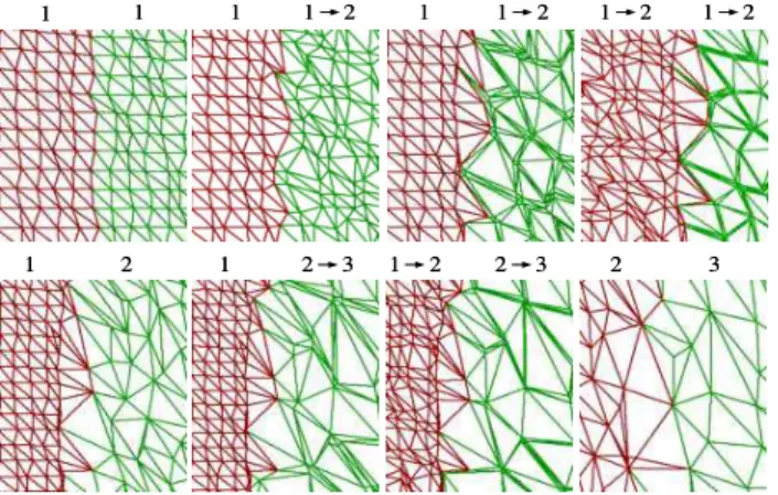
Figure 4: Illustration of how geomorphing is used to maintain con-nectivity along group boundaries by adjusting the geomorph ratio of the border points. Top row: boundary of two patches at the same LOD level. Bottom row: common boundary of patches separated by one resolution level. Numbers separated by an arrow indicate that the group is being geomorphed between these two levels.
immediately outside the viewing frustum, resulting in spatial pre-fetching. This step also performs pre-fetching in resolution space: since we use the distance to the bounding sphere along the view axis to determine the worst-case pixel size, growing the sphere results in selecting higher resolution geometry. The additional groups se-lected by this pass are queued to the paging thread for asynchronous loading. Patches that are loaded but have been culled in the current pass are tested with an even slightly larger bounding sphere than the one used for loading: if they are not included, they are unloaded. Using slightly larger spheres for unloading eliminates load/unload jitter effects when navigating at the boundary of a group’s loading sphere.
4.2 Geomorphing and Global Connectivity
Geomorphing is continuously applied to triangle patches during the entire interval over which they are selected for rendering. This very progressive interpolation aims at smoothing the transitions between levels of detail and at maintaining an almost constant on-screen res-olution. For each node being displayed, morphing is applied to dis-place the vertices of the rendered triangles along the trajectory of the original vertex aggregation paths computed during the simplifi-cation process. Other vertex attributes are all similarly interpolated. Non-boundary vertices are all morphed according to a unique ratio per patch, while boundary vertices are adjusted to maintain con-nectivity as described in the next paragraph. Geomorphing is per-formed directly on the GPU as part of the vertex program. When LODs are computed using a simplification algorithm that properly takes into account all vertex attributes, transitions become practi-cally hidden even when displaying at low resolution, due to attribute interpolation. We refer the reader to the accompanying video for a demonstration.
The GoLD method maintains the connectivity between adjacent patches as their levels of detail are selected and they undergo ge-omorphing at different ratios. It takes advantage of the fact that, even if neighboring groups are drawn as independent meshes at ren-dering time, their shared boundary points are part of a model that was simplified globally, rather than simplified on a per-group basis. Therefore, corresponding shared boundary points of neighboring groups are displaced between the different levels of detail along the exact same paths, since they correspond to the same original point
in the global simplified model. The following rules are applied to insure connectivity between corresponding points along boundaries of neighboring groups:
1. Corresponding boundary points are of the same level: in this simple case, illustrated in the first row of Figure 4, we simply apply the highest morph ratio of the visible groups sharing the point.
2. Corresponding boundary points are separated by one
resolu-tion level:in the case illustrated on the second row of Figure 4, we exploit the fact that a completely morphed point is at the same location than its corresponding unmorphed destination in the next level of detail. Points are connected by completely morphing the boundary points of the high resolution LOD and not morphing the boundary points of the low resolution one, this independently of the selected morph ratio of each visible group involved.
In the case where the neighboring points are separated by more than one level, there is no way to reconnect them simply by geomorphing the boundary points. Therefore this case must not occur during ren-dering. If the culling/refinement phase leads to such a situation, we simply promote the group that is at a resolution level that is more than one level lower than any of its visible neighbors up to one level below the level of the highest resolution neighboring group. It is possible to define combinations of a segmentation method, error metric and refinement criteria that insure that this situation will nat-urally never occur, therefore avoiding this validation step. However, since the number of patches we render per frame is relatively low, performing a post-processing validation to promote groups takes a negligible amount of time. In that context, the selected criteria to choose the visible patches during the culling/refinement step does not actually need to guarantee that this situation never occurs. The step of boundary points adjustment is the most important CPU overhead associated with our method, although it represents only a small proportion of the rendering time. For every frame, it in-volves assigning a ratio to each visible point, and making on av-erage slightly more than two comparisons per boundary point to determine whether its geomorphing ratio should be modified. A byte per visible vertex must be transmitted to the vertex program on the GPU, in the form of one vector per patch.
4.3 Implementation
Our real-time implementation is built on the OpenGL Performer scene graph [Rohlf and Helman 1994], and is integrated within the DIMENSION collaborative framework [Borgeat et al. 2004]. All vertex programs used to morph and render the models were writ-ten in the Cg language; the programs emulate the OpenGL lighting model with the addition of the geomorphing of all vertex attributes. Sources and destinations of points and attributes are cached in graphics memory using OpenGL’s vertex buffer objects, and tex-tures are managed using the texture object extension. A one byte per vertex morph ratio is uploaded at every frame for all vertices that are displayed using streamed vertex buffers. We currently have two layers of in-core loading for geometry and attributes. First, disk/network to system memory file access and decompression oc-curs, as just described, in a separate thread. We then perform the paging of data into the GPU memory by using the vertex buffer ob-ject and texture obob-ject extensions of OpenGL at the beginning of each frame in a synchronous manner. For geometry and attributes, this paging is done simply by uploading the data when it is first rendered, and unloading it as soon as it is no longer selected, al-lowing more free memory for resident textures. Texture paging on the GPU memory is implemented using the OpenGL texture objects
extension, that allows to set priority to textures to guide the graph-ics drivers when deciding which texture to page out due to lack of available memory.
5
Results
5.1 Preprocessing Performance
Our main preprocessing node is a Linux-based dual 1.6 GHz 64 bits AMD Opteron system with 8 GB of RAM and four swap parti-tions located on four 7200 RPM ATA drives. The decimation nodes are 1.6 GHz AMD Athlon PCs with 2 GB of memory. Only the simplification step was parallelized. A single node was used to decimate the small models, whereas four nodes where used for the large ones. Processing time for the various models range from un-der 15 minutes for models such as those of the duck or the crypt, to respectively 8 and 10 hours for the 250 million triangles col-ored model of a painting (Figure 5), and for Stanford’s St. Matthew dataset [Levoy et al. 2000] which is composed of 372 million trian-gles. For the large models, simplification accounted for 65% of the processing time, the stripping and re-ordering of the patches took another 30%, with the data reordering phase and the segmentation taking most of the remaining 5%. Texture processing for the entire terrain model required less than 10 hours on a four node cluster.
5.2 Visualization
We used two test systems for interactive visualization: a 2 GHz AMD Athlon nForce2 PC with 1.5 GB RAM and a GeForce 6800 ”Gamer Edition” GPU with 256 MB memory, and a dual 3.4 GHz Intel Xeon workstation with a 256 MB NVIDIA QuadroFX 3400 graphic card on PCI Express. All system ran Linux with NVIDIA drivers at version 1.0-6629.
The model in Figure 5 is of an oil painting on canvas made in 1883 by impressionist Pierre Auguste Renoir, titled “Femme nue dans un paysage”, and conserved at the Orangerie Museum in Paris, (inv RF 1963-13). It was scanned using the National Research Council of Canada’s color range sensor [Godin et al. 2002] at 50 µm lateral sampling rate and 10 µm depth resolution. The scan was made in collaboration with the French Museums Research and Restoration Center (C2RMF). This sensor acquires a color sample with each 3D measurement, thus naturally producing color-per-vertex mod-els. The painting model is composed of 250 million triangles and is divided into a tree of about 75,000 nodes. The high frequency contents in the color information and the very fine-grained nature of the 3D information make this dataset an interesting challenge for multi-resolution visualization algorithms: it cannot be easily sim-plified and therefore requires a large number of triangles to be ren-dered without any visual artefacts. The model of the duck (Figure 2 and video) was also produced using that sensor. The Byzantine crypt model in Figure 1 was built using a commercial Mensi range sensor combined with digital photographs, as part of a collabora-tion with the University of Lecce, Italy [Beraldin et al. 2002]. The texture parameterization was created from camera calibration data and photogrammetric techniques. The landscape model displayed in Figure 1 was produced from data gathered by Terrapoint [Ter-rapoint 2005], using their proprietary airborne ALMIS350 LiDAR system and a digital camera. The raw dataset was composed of 103 million data points and 6800 digital photographs of 4M pixels; calibration was performed using their proprietary software. The fi-nal model tree contains 120,000 patches and texture images, and 200 million triangles. The texture data, once compressed with the S3TC EXT1 OpenGL extension, still occupies over 20 GB of disk storage.
Figure 5: Rendering of the 3D model of a painting at two different resolutions. The larger image was rendered at 1280x1024, filling most of the screen. 1.83 million triangles are displayed at a rate of 50 million triangles/s. The insets contain 2.4 M triangles and are shaded using a raking light source. They produce similar rendering statistics.
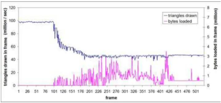
Figure 6 illustrates the rendering performance and the amount of data sent to the GPU in each frame during a sequence of navigation on the St. Matthew dataset. The plotted rendering time includes culling and view-dependent computations, upload to the GPU of new data, deletion of old data, and rendering of visible data. Our Xeon-based system offers about 15% less absolute graphics perfor-mance but faster pre-fetching than the Athlon setup, providing a globally better navigation experience. Groups at the lowest level of detail do not need geomorphing, which explains the higher perfor-mance at the beginning of the sequence, which starts far from the model. All the visible data is undergoing geomorphing at the end of the sequence. The graph illustrates the capability of the system to maintain its frame rate even when large amounts of new data must be uploaded. It also shows the overhead of applying geomorphing, which is approximately a factor of 2 on both test systems. This is explained by the fact that we need twice the number of attributes per vertex for geomorphed groups. The CPU computation of the boundary points morphing ratios accounted for 10% of the render-ing time for the St. Matthew sequence.
To appear in the ACM SIGGRAPH conference proceedings
Figure 6: Rendering performance at 1600x1200 for a sequence with rapid navigation. The bottom curve shows the amount of new data uploaded to the GPU during that frame. The data rendered in pre-vious frames is already cached on the GPU.
The amount of memory used for the application depends on the pre-fetching outreach configuration, the chosen resolution, as well as the type and number of attributes for the model. At high resolution, if we double the size of the bounding spheres for pre-fetching, the memory footprint for the painting model becomes approximately 500 MB for the whole application.
The benefits of geomorphing are hardly appreciable from still im-ages. We refer the reader to the accompanying video for se-quences of interactive navigation through the models and an an-imated demonstration of the behavior of the method. The video sequences, as well as the one used to produce Figure 6, were ren-dered at 1600x1200 resolution, a standard setup for high-quality vi-sualization. The video was generated by directly filming the LCD display. Model space error values derived from simplification were re-adjusted visually, toward optimized speed and image quality for visualization at 1600x1200. The final result would produce no visi-ble artefacts or noticavisi-ble resolution loss in normal mode, but would produce visible artefacts without using geomorphing. We used the Xeon system to generate sequences on the video. All out-of-core information in the models was accessed over a gigabit NFS con-nection to a file server.
As discussed in Section 4, the out-of-core paging and decompres-sion are implemented in a separate thread, and therefore only affect the rendering thread by using a part of the system resources. On the single CPU system, intensive group fetching during rapid nav-igation will reduce the frame rate and eventually affect the quality of the experience. On the dual Xeon system, the effect of paging for geometric models was only detectable by looking at actual per-formance statistics. The increased speed of the PCI Express bus also reduces the impact of uploading the geometry on that system, compared to the AGP 8X bus of the other system.
6
Discussion
Within GoLD, it would be possible to compute a different geo-morph ratio for each point of a patch instead of having a uniform one. By uploading to the GPU a model-space error value associ-ated with the geomorphing of each individual vertex, the vertex pro-gram could compute a ratio for each point individually. However, to avoid popping effects, we would still need to insure that all vertices are completely morphed before the replacement of the patch by its low-resolution parent in the tree, and completely expanded before switching to a higher resolution patch. The consequence of this last constraint is that this extra processing would not replace the need for specific computations for the borders, while requiring more data
to be uploaded to the GPU.
In the current implementation, we have chosen not to access the destination information for vertices and attributes using the vertex texture mechanism available on newer GPUs, even if it would in-stantly lead to a significant reduction in bandwidth and GPU mem-ory requirements. This gain would result from the fact that many vertices merge to the same destination in a patch, and that without vertex textures those destination values need to be repeated in ver-tex attribute lists. However, performance numbers from NVIDIA [Gerasimov et al. 2004] indicate that a GeForce 6800 can apply a basic displacement mapping to a surface at the rate of 33 million vertices/second. Since we would need many texture fetches per vertex for an object with attributes, we expect we would obtain a much lower performance for our application. However, assuming continuing speed improvements in future GPUs, this feature could become an interesting option for implementing the GoLD method. Also, in the context where we would display at a sufficiently high resolution to make transition effects acceptably small, it would be possible to implement only patch connectivity instead of full ge-omorphing at a very low resource cost, while still supporting arbi-trary segmentation. Indeed, by exploiting instruction branching fea-tures of new GPUs, vertex texture fetches would only be required for boundary points.
The obvious downside brought by the coarser granularity of the view-dependent resolution adaptation process is that we compute an error metric which is a worst case for the whole patch. The main consequence is the rendering of more triangle than necessary, but this is largely compensated by the global increase in performance brought by pre-optimization of patches. Another consequence is that, for a real-time error target of less than one pixel and even for slightly higher error targets, the fact that we render for a worst case will create area where numerous triangles project onto the same pixel, especially just before LOD transitions, potentially causing flickering similar to using textures without mipmapping. By hav-ing all the points and attribute values converghav-ing to their destination before the transition point with the next LOD groups, the geomor-phing approach can significantly reduce this effect.
7
Conclusion
We have presented GoLD, an efficient and versatile technique for view-dependent rendering of very large mesh models with texture or color. The method allows to display models at low or high res-olution through the use of geomorphing, thus providing more con-trol over the amount of real-time resources invested in the render-ing process. By allowrender-ing arbitrary segmentation of the model, the technique simplifies the management of texture derived from digi-tal photographs, and can be adapted for very efficient rendering of a wide variety of 3D model types.
Acknowledgments
We wish to thank our colleagues of the Visual Information Tech-nology Group at the National Research Council of Canada, in par-ticular Michel Picard, J.-Angelo Beraldin, Luc Cournoyer, Sabry El-Hakim, John Taylor, Marc Rioux, Daniel Gamache and Jean-Franc¸ois Lapointe. We also thank Prof. Virginia Valzano, of the University of Lecce (Italy), for kindly granting us the permission to use images of the crypt, Paul Mrstik and Kresimir Kusevic from Terrapoint Inc., and finally Pierre-Alexandre Fortin and Denis Lau-rendeau from Laval University.
References
AZUMA, D. I., WOOD, D. N., CURLESS, B., DUCHAMP, T., SALESIN, D. H.,ANDSTUETZLE, W. 2003. View-dependent refinement of mul-tiresolution meshes with subdivision connectivity. In AFRIGRAPH ’03:
Proceedings of the 2nd International Conference on Computer Graph-ics, Virtual Reality, Visualisation and Interaction in Africa, ACM Press, 69–78.
BERALDIN, J.-A., PICARD, M., EL-HAKIM, S., GODIN, G., VALZANO, V., BANDIERA, A.,ANDLATOUCHE, C. 2002. Virtualizing a Byzantine crypt by combining high-resolution textures with laser scanner 3D data. In Proceedings of the 8th International Conference on Virtual Systems
and Multimedia, 3–14.
BORGEAT, L., FORTIN, P.-A.,ANDGODIN, G. 2003. A fast hybrid ge-omorphing LOD scheme. In SIGGRAPH 2003 Sketches & Applications
(electronic proceedings), ACM Press.
BORGEAT, L., GODIN, G., LAPOINTE, J.-F., AND MASSICOTTE, P. 2004. Collaborative visualization and interaction for detailed environ-ment models. In Proceedings of the 10th International Conference on
Virtual Systems and Multimedia, 1204–1213.
CIGNONI, P., GANOVELLI, F., GOBBETTI, E., MARTON, F., PONCHIO, F.,ANDSCOPIGNO, R. 2003. Planet-sized batched dynamic adaptive meshes (P-BDAM). In VIS 2003: Proceedings IEEE Visualization, IEEE Computer Society Press, 147–154.
CIGNONI, P., MONTANI, C., ROCCHINI, C.,ANDSCOPIGNO, R. 2003. External memory management and simplification of huge meshes. IEEE
Transactions on Visualization and Computer Graphics 9, 4, 525–537. CIGNONI, P., GANOVELLI, F., GOBBETTI, E., MARTON, F., PONCHIO,
F.,ANDSCOPIGNO, R. 2004. Adaptive tetrapuzzles: efficient out-of-core construction and visualization of gigantic multiresolution polygonal models. ACM Transactions on Graphics 23, 3, 796–803.
CLARK, J. H. 1976. Hierarchical geometric models for visible surface algorithms. Commun. of the ACM 19, 10, 547–554.
DACHSBACHER, C., VOGELGSANG, C.,ANDSTAMMINGER, M. 2003. Sequential point trees. ACM Transactions on Graphics 22, 3, 657–662. D ¨OLLNER, J., BAUMAN, K.,ANDHINRICHS, K. 2000. Texturing
tech-niques for terrain visualization. In Proceedings IEEE Visualization 2000, IEEE Computer Society Press, 227–234.
DUCHAINEAU, M., WOLINSKY, M., SIGETI, D. E., MILLER, M. C., ALDRICH, C., ANDMINEEV-WEINSTEIN, M. B. 1997. ROAMing terrain: real-time optimally adapting meshes. In Proc. IEEE
Visualiza-tion ’97, IEEE Computer Society Press, 81–88.
DUMONT, R., PELLACINI, F., AND FERWERDA, J. A. 2001. A perceptually-based texture caching algorithm for hardware-based render-ing. In Proc. of the 12th Eurographics Workshop on Rendering, Springer-Verlag, London, UK, 249–256.
EL-SANA, J.,ANDBACHMAT, E. 2002. Optimized view-dependent ren-dering for large polygonal datasets. In VIS 2002: Proc. IEEE
Visualiza-tion, IEEE Computer Society Press, 77–84.
ERIKSON, C., MANOCHA, D., ANDWILLIAM V. BAXTER, I. 2001. HLODs for faster display of large static and dynamic environments. In
SI3D ’01: Proceedings of the 2001 Symposium on Interactive 3D Graph-ics, ACM Press, 111–120.
FERGUSON, R., ECONOMY, R., KELLY, W.,ANDRAMOS, P. 1990. Con-tinuous terrain level of detail for visual simulation. In Proceedings
IM-AGE V Conference, 144–151.
FUNKHOUSER, T. A.,ANDS ´EQUIN, C. H. 1993. Adaptive display al-gorithm for interactive frame rates during visualization of complex vir-tual environments. In Proceedings of ACM SIGGRAPH 93, ACM Press, New York, Computer Graphics Proceedings, Annual Conference Series, ACM, 247–254.
GARLAND, M.,ANDHECKBERT, P. S. 1998. Simplifying surfaces with color and texture using quadric error metrics. In Proceedings IEEE
Vi-sualization ’98, IEEE Computer Society Press, 263–269.
GERASIMOV, P., FERNANDO, R.,ANDGREEN, S. 2004. Shader Model
3.0 Using Vertex Textures. NVIDIA Corporation.
GODIN, G., BERALDIN, J.-A., TAYLOR, J., COURNOYER, L., RIOUX, M., EL-HAKIM, S., BARIBEAU, R., BLAIS, F., BOULANGER, P., DOMEY, J.,ANDPICARD, M. 2002. Active optical 3D imaging for heritage applications. Computer Graphics and Applications 22, 5 (sept.-oct.), 24–35.
GRABNER, M. 2001. Smooth high-quality interactive visualization. In
SCCG ’01: Proceedings of the 17th Spring Conference on Computer graphics, IEEE Computer Society Press, 87–94.
HOPPE, H. 1996. Progressive meshes. In Proceedings of ACM SIGGRAPH
96, ACM Press, New York, Computer Graphics Proceedings, Annual Conference Series, ACM, 99–108.
HOPPE, H. 1997. View-dependent refinement of progressive meshes. In
Proceedings of ACM SIGGRAPH 97, ACM Press, New York, Computer Graphics Proceedings, Annual Conference Series, ACM, 189–198. HOPPE, H. 1998. Smooth view-dependent level-of-detail control and its
application to terrain rendering. In Proceedings IEEE Visualization ’98, IEEE Computer Society Press, 35–42.
HWA, L. M., DUCHAINEAU, M. A., ANDJOY, K. I. 2004. Adaptive 4-8 texture hierarchies. In Proc. of IEEE Visualization 2004, Computer Society Press, Los Alamitos, CA, IEEE, 219–226.
ISENBURG, M.,ANDGUMHOLD, S. 2003. Out-of-core compression for gigantic polygon meshes. ACM Transactions on Graphics 22, 3, 935– 942.
ISENBURG, M., LINDSTROM, P., GUMHOLD, S., ANDSNOEYINK, J. 2003. Large mesh simplification using processing sequences. In Proc.
IEEE Visualization, IEEE Computer Society Press, 465–472.
LEVENBERG, J. 2002. Fast view-dependent level-of-detail rendering using cached geometry. In VIS 2002: Proceedings IEEE Visualization 2002, IEEE Computer Society Press, 259–265.
LEVOY, M., PULLI, K., CURLESS, B., RUSINKIEWICZ, S., KOLLER, D., PEREIRA, L., GINZTON, M., ANDERSON, S., DAVIS, J., GINSBERG, J., SHADE, J.,ANDFULK, D. 2000. The Digital Michelangelo Project: 3D scanning of large statues. In Proceedings of ACM SIGGRAPH 2000, Computer Graphics Proceedings, Annual Conference Series, ACM, 131– 144.
LINDSTROM, P.,ANDPASCUCCI, V. 2002. Terrain simplification simpli-fied: a general framework for view-dependent out-of-core visualization.
IEEE Transactions on Visualization and Computer Graphics 8, 3, 239– 254.
LINDSTROM, P.,ANDTURK, G. 1998. Fast and memory efficient polyg-onal simplification. In Proceedings IEEE Visualization ’98, IEEE Com-puter Society Press, 279–286.
ROHLF, J.,ANDHELMAN, J. 1994. IRIS Performer: a high performance multiprocessing toolkit for real-time 3D graphics. In Proc. of ACM
SIG-GRAPH 94, ACM Press, New York, ACM, 381–394.
RUSINKIEWICZ, S.,ANDLEVOY, M. 2000. QSplat: a multiresolution point rendering system for large meshes. In Proceedings of ACM
SIG-GRAPH 2000, ACM Press/Addison-Wesley Publishing Co., Computer Graphics Proceedings, Annual Conference Series, ACM, 343–352. TANNER, C. C., MIGDAL, C. J.,ANDJONES, M. T. 1998. The clipmap:
a virtual mipmap. In Proceedings of ACM SIGGRAPH 98, ACM Press, New York, Computer Graphics Proceedings, Annual Conference Series, ACM, 151–158.
TERRAPOINT. 2005. Terrapoint Inc. http://www.terrapoint.com/. YOON, S.-E., SALOMON, B., ANDMANOCHA, D. 2003. Interactive
view-dependent rendering with conservative occlusion culling in com-plex environments. In VIS 2003: Proceedings IEEE Visualization, IEEE Computer Society Press, 163–170.
ZWICKER, M., R ¨ASANEN¨ , J., BOTSCH, M., DACHSBACHER, C., AND
PAULY, M. 2004. Perspective accurate splatting. In GI ’04:
Proceed-ings of the Graphics Interface Conference, Canadian Human-Computer Communications Society, 247–254.