~ASSACHlJSrnSINSTITUTE
o~Tt:f\UUf'1'"~,,
JUL 17
1995
i\RCHIVES
Adam Barry Feder
Submitted to the Department of Electrical Engineering/
Computer Science in partial fulfillment of the
requirements for the degrees of
Bachelor of Science and Master Of Science
at the
MASSACHUSETTS INSTITUTE OF TECHNOLOGY
January 26, 1995
© Adam Barry Feder, 1995. All rights reserved.
The author hereby grants to MIT and Hewlett-Packard Limited
permission to reproduce and distribute publicly paper and electronic
copies of this thesis document in whole or in part.
Author
. Y••• • , ... _ • • • • • • • • • • • • • • • • • • • • • • • • • • • • • • • • • • • • • • • • • • • • • • • • • • • • • • • • • • • • • • • • • • • • • • • • • • • • • • • • • • • • • •Electrical Engineering/ Computer Science
January 26, 1995
Certified by
.
Professor Steven R. Lerman
Civil and Environmental Engineering
Thesis Advisor
Certified by
-..,
..-
.
Simon Towers
Hewlett -Packard Laboratories
Thesis Advisor
UBht'\I'1I::',;;.o
A
d b
ccepte
y
) .,,,•.,,..
,.~
..
w.T"~~d~ri~ 'R:-M~~~~~~h~i~;
by
Adam B. Feder
Submitted to the Department of Electrical Engineering/Computer
Science on January 26, 1995, in partial fulfillment of the
requirements for the degrees of Bachelor of Science and
Master of Science.
Abstract
Dolphin is a system which manages distributed computers and applications. It applies
general management algorithms to declarative descriptions, called models, of the types of
entities it manages. Because Dolphin needs a model for everything that it manages, many
models need to be created and debugged. Models are difficult to develop, so an interactive
debugging framework was created. Tools in this framework make the state of the
computation explicit to the modeller, present information in the modeller's terms, and
provide specialized controls for the tasks. This thesis describes the design and
implementation process of that system.
Thesis Supervisor: Professor Steven R. Lerman
Title: Professor Of Civil and Environmental Engineering, MIT
Thesis Supervisor: Simon Towers
Acknowledgments
I need to thank the entire Dolphin team for making me make the debugging tools and this
thesis far better than I wanted to make them. They were always willing and able to talk
through ideas and to provide the necessary feedback to allow me to make my tools useful.
For their help and guidance, I am very grateful to Kave Eshghi, Jean-Jacques Moreau,
Adrian Pell, Simon Towers, Sergei Dubinin, and Benjamin Thomas. As my office mates,
Ben and Anne-Isabelle deserve special mention for putting up with me. The members of
the OpenView AdminCenter team also gave me valuable feedback.
Professor Lerman was a very flexible advisor, calmly helping me in a project 3,000 miles
away from him. His advice, especially when not heeded, was always correct.
Heather McCallum helped tremendously, by reading and constructively criticizing zillions
of drafts of the thesis. Her sharing my non-thesis time-travelling and exploring
Europe-kept me happy and sane.
Lastly, and probably most importantly, I need to thank my parents, Eric and Sharon Feder,
for their constant support these past 22 years. Without their help, I would never have had
to do this thesis!
1 Introduction ... 11
1.1 Dolphin background ...
11
1.2 M odelling ...
... 12
1.3 Dolphin Modeller's Development Environment...
....
14
1.4 Focus of this thesis ...
16
1.5 Development path ... 17
1.6 Proposal ... ... 17
1.7 Previous work...18
1.8 Com pleted work ...
18
1.9 Thesis organization ... ...
...
... 19
2 W hat are debuggers? ... ... 21
2.1 What are debuggers? ... 21
2.2 General requirements for debuggers ...
... 22
3 D ebugger A rchitecture...
... 25
3.1 How a system administrator uses Dolphin ...
.... 25
3.2 How Dolphin modules cooperate to help system administrators ... 30
3.3 Model Development Environment ...
... 32
4 Inference D ebugger ... ... 35
4.1 What is inferencing?...
. . . ... . ... . . . . ... . . . ....... 35
4.2 How Dolphin's inference engine works ...
... 36
4.3 Designing the debugger...
45
4.4 Instrumenting the system ...
... 53
4.5 Inference debugger presentation ... 68
4.6 The explanation facility ...
... 74
4.7 Weaknesses and future work...
75
5 Q uery/Event D ebugger ...
... 79
5.1 What are querying and event handling? ...
... 79
5.2 How Dolphin's query system works ...
... 80
5.3 Designing the debugger...
... 86
5.4 Instrumenting the system ...
...
89
5.5 Query debugger presentation ... ...
90
5.6 Weaknesses and future work...
94
6 Fixer D ebugger ... ... 97
6.1 What is fixing? ... 97
6.2 How Dolphin's fixer works ...
97
6.3 Designing the debugger...
104
6.4 Instrumenting the system ...
...
107
6.5 Fixer debugger presentation ...
109
6.6 Weaknesses and future work ...
112
7 T ool Policy ...
. . ... 115
7.1 Possible tool policies ...
115
7.2 Abstracting the tool policy ...
117
8.1 Completed work...1...23
8.2 Judging our progress ... 123
8.3 Future directions...
... 124
Figure 1 Instance browser on the printer named 'elm' ...
.... 26
Figure 2 Dolphin's explanation of why
elm
is not ok. ...
.... 27
Figure 3 An instance browser showing netman's attributes ...
28
Figure 4 A collection browser on the users of the machine called 'netman'...28
Figure 5 A prompt for information used to create a user... 29
Figure 6 System administrator's conceptual model of Dolphin's mechanisms...29
Figure 7 The Dolphin prototype's major modules...32
Figure 8 Model development environment...33
Figure 9 Some basic printer relations ...
38
Figure 10 A derived relation for printers ...
... 38
Figure 11 Initial state of proof ... 39
Figure 12 After removing and proving the
namegoal...
...
39
Figure 13 State after expanding isOk...40
Figure 14 State after proving onLine ...
40
Figure 15 State after proving paperOk...41
Figure 16 A simple way to test both 'elm' and 'oak' ...
42
Figure 17 Initial state of the inference engine ...
42
Figure 18 After choosing to try the 'oak' alternative ...
42
Figure 19 Immediately before the proof fails because oak's paper supply is not ok...43
Figure 20 Using the fact base to decide which printers to test ... 44
Figure 21 Goal to ask if there is a known printer which is not ok ...
44
Figure 22 Goal to ask "Is there a known printer which we can not prove is ok?" ... 45
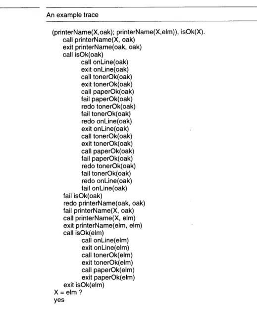
Figure 23 An example trace ... 47
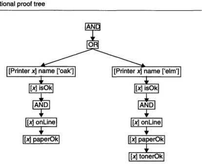
Figure 24 Traditional proof tree...48
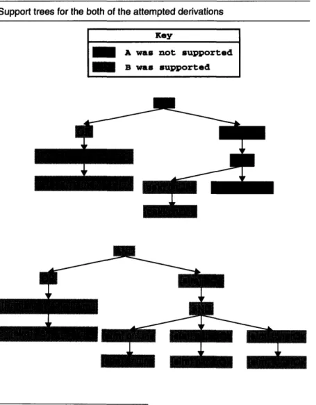
Figure 25 Support trees for the both of the attempted derivations ...
49
Figure 26 An example spy interaction ... ..
...
51
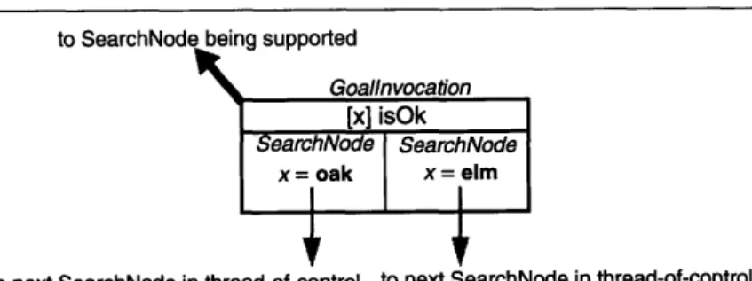
Figure 27 A GoalInvocation which was entered twice, and thus has two SearchNodes ...54
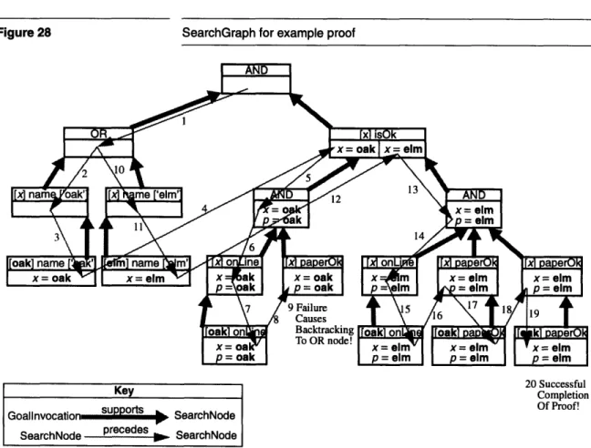
Figure 28 SearchGraph for example proof ...
55
Figure 29 Support graph for the proof of:
-[Printer x] name ['soseki'] AND [Printer y] name ['elm'] ...
56
Figure 30 SearchGraph for the proof of:
-[Printer x] name ['soseki'] AND [Printer y] name ['elm'] ...
56
Figure 31 The number of bindings stored in proof using each representation ... 58
Figure 32 SearchGraph for example proof using BindingArrayDeltas instead of copies .58
Figure 33 Computing thread-of-control success for SearchNode...
60
Figure 34 Support success computation procedures ...
61
Figure 35 Support success procedure for - (negation as failure) expressions...62
Figure 36 The inference engine making calls on its ProofState ...
65
Figure 37 The ProofState pausing the proof so the user can see it ...
66
Figure 38 Illustration of step over thread-of-control (on a thread-of-control graph) ... 67
Figure 39 Illustration of step over kids (on a support graph) ...
68
Figure 40 Explicit Choicepoint Dictionary ...
69
Figure 44 A snapshot of the debugger showing a previous thread-of-control...74
Figure
45
End-user explanation of why
oak
is not ok...
....
74
Figure 46 Some basic UnixUser relations ...
...
81
Figure 47 Some basic relations on a UnixMachine ...
... 82
Figure 48 Some basic relations on an OperatingSystem ...
... 82
Figure 49 Query definition used to find the details about a user, given its user name...82
Figure 50 Another query definition used to find the details about a user, given its user
n am e ...
... 83
Figure 51 "Levels" of computation in the query system ...
... 88
Figure 52 Snapshot of top part of query debugger's presentation ...
91
Figure
53
Snapshot of the embedded inference debugger ...
92
Figure 54 Snapshot of the parsing display ...
93
Figure 55 Snapshot of the assimilation details ...
... 94
Figure
56
Basic relations for UnixMachines ...
...
98
Figure
57
Basic UnixUser relations ...
98
Figure 58 Basic OperatingSystem relation ...
98
Figure 59 Basic Directory relations ...
98
Figure 60 More basic UnixUser relations, for dealing with Directories...98
Figure 61 A derived UnixUser relation ...
99
Figure 62 Action description useful for adding a UnixUser to a UnixMachine ...
99
Figure 63 Action description useful for making a Directory ... 100
Figure 64 Action description useful for adding a UnixUser to a UnixMachine, using the
adm in tool ...
... 100
Figure 65 A proof tree supporting our target goal ...
101
Figure 66 Actual support tree for our goal...
...
101
Figure 67 Support graph found by diagnosis proof ...
102
Figure 68 Action descriptions useful for each residue goal...
102
Figure 69 Plan of actions to execute and the goals each action satisfies ... 104
Figure 70 "Levels" of computation in the fixer ...
106
Figure 71 Snapshot of the top half of the fixer debugger ...
110
Figure 72 Snapshot of the bottom half of the fixer debugger ... 111
Figure 73 The plan select list's menu displays the residue goals satisfied by the selected
action ... 112
Figure 74 Boolean tool policy interface ...
115
Figure 75 Boolean-for-each-type-of-tool tool policy ...
115
Figure 76 Yes-no-maybe tool policy interface ...
116
Figure 77 All-none-selected policy interface ...
116
Chapter 1 Introduction
Dolphin is a tool designed to simplify a system administrator's job by providing him with a coherent interface for browsing and changing the state of the devices, applications, and services under his control. Dolphin uses descriptions called models to accomplish its job. This thesis outlines the requirements for an interactive environment suited to creating these models and describes the design and implementation of the debugging tools for that environment.
The Dolphin prototype is written in Smalltalk and has been developed over the past four years. The work described in this thesis was done over the course of eight months.
1.1 Dolphin background
Today's open, distributed systems are composed of devices, applications, and services with widely varying system management needs. As businesses begin to use such systems, they find that the management costs are far worse than for old-fashioned, closed, proprietary solutions. Dolphin is a system being developed to overcome these costs by simplifying the management task, allowing system administrators to more effectively manage devices and applications. The Dolphin system is the prototype for HP's OpenView AdminCenter product which should be
mass-released during the first half of 1995.
Dolphin simplifies the system administration task by presenting a single user interface to the system administrator through which he can accomplish the common management tasks-installation, configuration, fault diagnosis, upgrading and deinstallation. Dolphin accomplishes this by having general algorithms for each management task which it applies to specific descriptions of types of objects in the world. Its algorithms find the differences between the real world and the desired world and act to bring about the desired state. For example, knowing that a UNIXI user must be listed in a machine's password file with a user id, a legal password, a home directory, and a shell to be able to log in to that machine, Dolphin can arrange log in access for a user by providing him with those things, determine why a user can not login by finding which criteria are not met, or prohibit login by ensuring the user does not meet the requirements.
To apply its general algorithms to specific types of real world objects, Dolphin must be given descriptions of the real world. These descriptions are called models. Models contain declarative descriptions of the characteristics of objects and of the relationships between objects.
1. UNIX is a registered trademark in the United States and other countries, li-censed exclusively through the X/Open Company Limited.
Dolphin provides mechanisms for retrieving information about and changing the real world. Models need only describe how to relate the information to its internal model of the world and what actions to take to achieve desired results. Dolphin's managing algorithms also provide the thread of control which uses the descriptions. A model needs only to describe the object or system to be managed, not how to manage it. To be a practical management solution, Dolphin requires models of
everything that needs to be managed. Practically, Dolphin can only provide a framework into which new models should fit. It can not provide all necessary models. Ideally, the creators of new products will produce Dolphin models for them as they produce the products. One could even imagine that the products would be more manageable if the models were to be developed in conjunction with the products themselves. To create and debug all needed models, there will be many people writing models, and these modellers will need a helpful environment to accomplish their task. This thesis describes the requirements of such an environment, and designs and implements a subset of that environment. This work will feed
into the next major release of AdminCenter.
This chapter provides an overview of modelling, presents the requirements for a model development environment, the focus of the
work done on the environment, and the organization of this thesis.
1.2 Modelling
Dolphin's models2 are written in the Dolphin language (see [8]). They consist of two main types of description. The first type describes the objects to be managed-their attributes and how they interrelate; Dolphin uses these descriptions to build an internal model of the real world. The second type of description describes how to translate between Dolphin's internal model and the real world itself.
1.2.1 Object definitions
Object instances, which represent real-world objects, are described by their attributes, which are expressed as logical relations between one or more object instances. Relations are described in object definitions3. For instance, the Printer definition may be used by the instance representing our printer named 'elm'.
2. The word model is overloaded in Dolphin. In one usage, it means Dol-phin's internal construction which represents its knowledge of the real world. Its other usage is Dolphin jargon meaning a specific grouping of object, ac-tion, query, and event descriptions. Context will usually be enough to distin-guish these uses.
Two types of relations can be defined-base and derived. Base relations represent facts from the real world. For instance, base relations for a printer might describe whether or not a printer is on-line and whether or not its door is open. Base relations describing a printing service might state that a computer is a print server for a printer.
The values for derived relationships are logically computed from the values of other relationships. For instance, one derived relation might state that a printer isOk if it is on-line and its door is not open. Another relation might state that a computer canPrintTo a printer if the computer is the print server for that printer and the printer isOk.
Notice that derived relationships allow us to abstract the low level details from our high level descriptions. For instance, we can use the isOk relationship to describe the canPrintTo relationship. In Dolphin, different printers can define isOk differently, but the high-level relation is indifferent to those details.
Describing objects in Dolphin is simplified because one type of object is allowed to inherit from another type. For instance, the HPLaserPrinter description might inherit from the LaserPrinter description. As a result, an HPLaserPrinter can be used wherever a LaserPrinter can be used and the HPLaserPrinter definition only needs to describe how it differs from the LaserPrinter definition.
1.2.2 Translation definitions
Dolphin contains a model of the state of the world in terms of logical object relations and it reasons about the world based on this model. Queries, events, and actions are used to ground the model in the real world, translating real world status information into changes in the model's state and transforming Dolphin's desired changes into commands to affect the world. Standards such as the Simple Network Management Protocol (SNMP) have evolved to provide access to information and to allow configuration of real world devices. Dolphin takes advantage of such protocols when gathering information and acting on the world. Queries and events are used to translate information from the real world into Dolphin's model of the world. When Dolphin wants information about something, it uses a query description to ask for information and interpret the result. When the real world notifies Dolphin of changes in the world, Dolphin uses an event description to interpret the notification. These descriptions include information about how to parse responses, how long to believe the answers, and preconditions stating when it is valid to use the descriptions. Unix commands and SNMP-gets are two supported query types. Events from a primitive event generator are supported and work is underway to support events generated by HP's OpenView
OperationsCenter product.
When Dolphin decides to fix the real world, it uses action descriptions to find out how to do it. Action descriptions contain preconditions for their
use, what to do, and what the expected outcome is. Actions are not assumed to do what was expected even if they report success. Instead, Dolphin invalidates any facts it thinks may have changed as a result of the actions, so that the real world will be queried next time the information is needed. Unix commands and SNMP-sets are two types of actions currently supported.
1.2.3 Models
Models are used to group objects, actions, queries, and event descriptions together. A model can import other models to have access to their descriptions. There can not be a cycle in the importations, but a mechanism exists to extend previously defined object descriptions.
1.3 Dolphin Modeller's Development
Environment
The process of developing a Dolphin model has three main tasks-entering the model, testing and debugging the model, and checking the model. Rather than making these three independent tasks, the development environment should allow work on the tasks to be interleaved. For instance, after a query description has been entered, it should be possible to try the query interactively to debug it and to check how it relates to the rest of the model.
Individually, each of these tasks places several requirements on the functionality of each part of the environment. The smooth integration of these tasks places other requirements on the environment as a whole.
1.3.1 Entering models
Modellers must be able to enter models. At a minimum, they must be able to enter them as text in the Dolphin language and have them compiled. We would prefer that they be entered graphically to simplify the entry of complex rules and to constrain the types of errors that can be made. It will be impossible to make a syntax error if the user does not write code, and type errors can be avoided if only valid options are presented to the user. Like other interactive development environments, Dolphin's modeling environment will need to provide easy cross-referencing between relations and various presentations of the relationships. For instance, inheritance and importation graphs would be very useful. Similarly, when the modeller wants to change a relation, it should be easy for her to find all uses and implementations of it.
When entering models, it is not always possible to keep the model entirely consistent because changes may need to be made in more than one place. The environment should provide support for maintaining a set of inconsistent descriptions and for accepting them into the model later.
become invalid. Such invalid relations should be clearly marked for the modeller.
Like the development of any quality software, the development of production-quality models requires a process. A useful development environment should support such a process. Multi-person model development spawns many interesting problems. At the very least, some form of model revision control is needed. We are not yet sure at what granularity such control should be provided.
Automatic creation of models from the specifications of management standards would greatly ease model development. For instance, in many cases it should be possible to generate the needed base relations, query, event, and action descriptions from standard specifications, such as SNMP Management Information Base specifications. The modeller may still need to organize the base relations and write derived relations, but such a creation process could greatly simplify model writing.
1.3.2 Testing and debugging
To best provide an interactive development process, the development environment must allow each part of the description to be tested easily as it is created. The modeller should not have to contrive a way to invoke the description. For instance, while developing a query, she4 should be able to invoke the query, entering any information the system would normally provide, and then be able to watch the query execute. While defining a derived relation for an object, she should be able to see the value that relation would have for each known instance.
Not all mistakes can be caught through unit testing, so the environment must provide a system for debugging the system during actual operation. This requires providing the modeller with all of the information that a model has access to. One major repository of state is Dolphin's fact base, which stores everything known about the real world. Modellers should be able to see its contents and add or remove facts. It should also be easy to ask it to spawn a query to refresh its facts. Whenever a modeller needs to select an object (for instance during unit testing of a query) she should be able to select one from the fact base.
A modeller should be able to watch Dolphin use descriptions, seeing all of the programmer-visible state. This includes how and why a query, event, or action is chosen as well as how it is executed.
The environment should allow its user to exercise a model as early as she would like to, even before it is complete. By allowing the modeller to use the model and correct it incrementally, the model can be organically grown rather than written as a whole and then tested. To allow this
4. In this thesis, we will be constantly discussing two types of users-system
administrators and modellers. To help the reader distinguish between them, we will refer to the system administrator as he and the modeller as she.
development style, a modeller should be able to enter needed facts when a query is unavailable or fails. Similarly, a modeller should be able to tell Dolphin what action to take when no action is available or if the chosen action is incorrect.
1.3.3 Checking
There are many checks that a modeller may find useful. They range from needed consistency checks to desired completeness checks.
Consistency checks ensure that the model is intelligible to Dolphin. They answer the following types of questions: Are the models syntactically correct? Do the relations they use exist? Are they properly typed? Dolphin itself needs these checks to compile and use the descriptions. Completeness checks are the checks that a modeller would want to have performed before releasing her models. They answer questions such as: Do all base relations have related queries and actions? Are there situations in which no queries or actions for a relation would be found? Does this model make sense?5 Does the search space by the model contain infinite branches which may trap Dolphin's inference engine?6 Is there a better ordering for derived rules which will allow faster execution? Would the model allow any of the following general guidelines to be broken? If so, when and how?
1.3.4 Integration requirements
To make the environment a coherent whole and to allow modellers to transition between tasks smoothly, several additional requirements must be imposed. First, when a description is modified using one tool, the change should be visible to all other tools. Second, if a graphical interface style is adopted to represent objects and relations, it should be used throughout the system, not just for the entering task. Third, it should be possible to switch between entering, testing, and checking as desired.
1.4 Focus of this thesis
The previous sections propose many requirements for a complete model development environment. They also propose several diverse areas of research, from creating a highly interactive set of development and testing tools, to creating a novel GUI for programming, to providing support for a full model development process, to research into how to do completeness checks on models. In this thesis, we have focussed on a part 5. The big question here is what does it mean to make sense? What needs to be true about the model for it to be a reasonable model?
6. Although this is a difficult problem in the general case, we think that for the special case of practical models, we may be able to make some checks to
of that work. Specifically, we have concentrated on the development of useful, interactive debugging tools. We chose this because it was the most critical weakness of the Dolphin system at the time. It was already possible to enter models manually in a text format, work on a graphical user interface was progressing at the Palo Alto site, and another student was to begin her Ph.D. on automatic model generation soon. We felt that until a modeller could reasonably debug her model, automatic completeness checking would be irrelevant. Further, we felt that until we could support one modeller in creating working models, efforts to enable team programming would be superfluous.
Personal experience trying to model sendmail, the Unix mail delivery agent, and feedback from both Dolphin and AdminCenter modellers confirmed that debuggers had the highest priority ([15], [2]).
A complete debugging system would consist of tools specialized for each type of description tied together by the ability to invoke them from each other as needed. There would be tools for monitoring and debugging proofs, queries, events, and actions. The modeller would be able to invoke unit testing on each part of the description. The modeller would be able to see and override the selection of translations as well as manually enter the data that should be retrieved.
1.5 Development path
The development of a complete suite of debuggers is still a large task. To facilitate incremental development, we divided the work into four stages based on the functionality provided. The first stage should allow a modeller to enter models textually and to watch all of the modeller visible state during the execution of a proof. The second stage should allow a modeller to do unit testing-selecting a query, action, or event, and having Dolphin execute it. The third stage should allow a modeller to direct Dolphin's execution, entering or correcting data, commands, and results. The fourth stage would concentrate on trying to get the system to help
create the necessary query, event, or action description when it discovers
at runtime that it does not have an appropriate one. For instance, since one of the most difficult parts of creating a model is describing the parsers for queries and events, we would like to build a system in which the parser can be created by highlighting sample data returned from a query.
1.6 Proposal
Once a focus and staging were chosen, we still had a choice about which development sequence was the most appropriate. Would we work on one debugger to take it as far as we could, or would we provide stage one functionality for all tools before proceeding with stage two? We chose the later. We proposed to provide stage one capabilities for all Dolphin
systems. If any time was available after that, it would be used to extend the query tools beyond stage one.
1.7 Previous work
When we were beginning, two interactive debuggers were available for Dolphin, one for inferencing and one for queries. In addition to their each having individual weaknesses, they were not integrated.
The inference debugger allowed modellers to watch proofs. It had three main weaknesses-it provided little information, what it did provide was presented poorly, and it offered little control to the modeller. Additionally, it had just become obsolete with the implementation of a new inference engine.
The query debugger provided a reasonable amount of information about the execution of queries, but it did not help the user debug query selection.
1.8 Completed work
We have completed stage one for proofs, queries, events, and actions, and also developed a framework to enable useful debugging. This framework provides the ability to set policies about which debugging tools should be used and when. It provides solutions to several requirements common to all debuggers. We also adapted the proof debugging tools to prototype graphical explanations for Dolphin's end-users.
These tools have proven themselves useful in practice, having been used extensively by the Dolphin team both to develop new models and to debug and improve the Dolphin system itself.7 Because they make the Dolphin's use of models explicit, they have also been useful to both teach new modellers and to demonstrate the system.
We distinguish between the essence of a debugger and its presentation.8 The essence gathers information about the execution of the system and provides flow control - the ability to start and stop the execution. The presentation is responsible for interacting with the user, displaying the debugger's state and directing the essence based on the user's commands. This distinction is realized in the implementation of the tools so they can more easily be used with better interfaces when they become available.
7. For instance, the debugger has shown us when the underlying system mis-used rules to provide defaults. The researcher responsible for the development of both the inference engine and the fixer has said several times that the de-velopment of the action system would have taken an order of magnitude
long-er without the inflong-erence debugglong-er. Dolphin Model Developers' Environment
Despite wanting to invest only a limited amount of time in the presentations of the tools, we developed a very useful graphical, interactive presentation for proofs. Traditionally, the search done by inference engines is very hard to present, because it involves exploring a space with a high number of dimensions (one per choice point). Using the computer, however, we only need to show one slice through that search space at a time, allowing the user to interactively decide which slice to show. Additionally, the proof is displayed as an and/or tree instead of in a way dependent on the system's exploration order.9
We also developed a set of implementation techniques for gathering information and providing flow control points in such a way as to not cause much overhead when the tools are not in use. We use multiple implementations of the objects representing debuggers to minimize the duplication. Essentially, Dolphin always runs a debugging version of the systems, but most of the time the "debugger" causes very little computational overhead. More details about this technique can be found in Section 4.4.3.
1.9 Thesis organization
This first chapter presents an overview of Dolphin's purpose and technology, presents the need for a model development environment and outlines what might be included in a "complete" environment, and, finally, describes the focus and structure of the thesis. Chapter 2 provides a framework for describing debuggers and uses it to describe our work. Chapter 3 describes Dolphin's architecture and leads into the architecture of the developed debugging framework.
Chapters 4, 5, and 6, describe the Inference, Query/Event, and Fixer debuggers, respectively. Each chapter describes the system to be debugged, the information and types of control the modeller would like, and an implementation which meets those needs. Because Dolphin concepts and implementation techniques are covered as needed, material in the earlier chapters is often required to understand later chapters. It should be possible to skip later sections of each chapter and their corresponding sections in later chapters. Someone interested in Dolphin's architecture may enjoy the first parts of each chapter. A modeller interested in using the tools may ignore the implementation details. Chapter 7 describes the "ToolPolicy", which allows modellers to designate which computations they are interested in debugging.
Chapter 8 summarizes the strengths and weaknesses of the work, pointing out paths for future work.
9. We have since found that the Transparent Prolog Machine developed at the Open University in the United Kingdom provides a similar type of display.
In the previous chapter, we described Dolphin's purpose and how it uses models to accomplish that purpose. We also looked at the broad requirements for a Dolphin model development environment and the rationale for concentrating on tools to debug models. In this chapter we investigate what we mean by debugging and develop general requirements for our debuggers.
2.1 What are debuggers?
Taken literally, "debugging" is the process of removing errors (a.k.a. bugs) from programs, so literally, "debuggers" must be tools which remove errors from programs. In reality, debugging is mostly concerned with finding errors, and debuggers are tools which help programmers find and remove their bugs. Different debugging tools provide a wide range of information and features to help with this process. We can measure these abilities along five axes - data gathering, data presentation, flow control, error detection, and program correction.
Data gathering involves collecting information about the state of a
computation. Some debuggers only take snapshots of a computation's state. For instance, an assembly language debugger will show the state of a machine's registers and memory. Other debuggers capture the flow of control in a program or a sequence of states. For instance, traditional logic language debuggers provide a trace feature which prints out what rules
were used and what variables were bound.
Data presentation is the art of showing the collected data to the user. Some
debuggers present the information in a "raw" state and others map the data into higher-level concepts. Assembly-level debuggers, which just show the state of the registers and memory, present their information without much interpretation. Source-level debuggers, on the other hand, make an effort to present the state of the machine in terms of the original program. Even more advanced debuggers might present a program's state in terms of the abstract operations being done instead of in terms of statements and procedures.
Flow control features allow the programmer to actually step through the
computation as it is performed. A simple trace facility is an example of a debugger with no flow control features; it simply prints out which parts of the program are being executed. We can contrast simple trace facilities with source-level debuggers which allow the user to step from command to command. Other common flow control features include the ability to "step into" procedure calls to see the details of their execution or to "step over" calls to ignore their execution.
Error detection features help the user narrow down where to look for an
error. Some debuggers stop when they detect an error and allow the programmer to examine the state to try to find the error. One problem with this kind of debugger is that it can only find serious errors, such as uninitialized variables or the failure of assertions provided by the programmer; they can not find errors which only result in faulty output.
Shapiro [10] describes debuggers which, given the program trace of a faulty program, actually search for errors, using answers to a series of questions posed to an oracle (usually the programmer) to zoom in on the problem area.
Program correction is offered in very few debuggers. Most debuggers are content to
help the programmer find the error by allowing them to watch the execution. Not content with that, Shapiro describes debuggers which actually correct or help the programmer correct the error once it is found and continue the computation.
In this thesis we concentrate on developing interactive tools which gather snapshots of Dolphin's state during its execution, present the information in the modeller's high-level terms, and allow the user to control the flow of the execution in suitable ways. We provide the framework for notifying the modeller of simple errors (see Chapter 7). We do not yet attempt advanced error detection or correction as discussed in Shapiro's work, but the gathering we do could provide the information needed for incorporating such capabilities.
Because there are other people working on novel graphic representations of Dolphin models, we concentrate on the gathering and controlling. We provide basic interfaces which make the tools useful and prove that the gathering and controlling are correct.
2.2 General requirements for debuggers
The general requirements guiding the design of the debuggers had three main sources. The first set were determined by the type of debuggers we wanted to create. The second set of requirements arose from the day-to-day use of the tools by members of the Dolphin team. The third set are practical constraints on the implementation of the debuggers derived from both computational and human resource limitations.
2.2.1 Requirements from desired features
The system must be able to gather and present information incrementally so that we can provide the required flow control and be able to provide views of the computation at each intermediate point. The system should be able to rewind the presentation to show previous parts of the execution because, in our experience, realizing that the bug has just happened but that we missed seeing it is one of the most frustrating parts of debugging. Supporting such rewinding can consume a great deal of resources, so in some cases, it may not be possible. We will discuss these cases as they arise.
Debuggers need to present information in a modeller's terms. This in turn places requirements upon what information needs to be gathered from the system. Although we wanted to avoid concentrating on developing user interfaces, we have had to develop presentations that display the information in modeller's terms in order to insure that we were gathering enough information. For instance, the first implementation of the inference debugger was driven by the needs of a simple interface, which neither presented the proof clearly nor provided sophisticated flow control. When we realized what we really wanted to know and how we really wanted to control the proof, we had to collect more sophisticated information.
In addition to providing invaluable suggestions about what information and controls were needed for each tool, Dolphin team members using the tools also contributed an extremely important general requirement for all debuggers. They found that the tools provided too much information and suggested several ways to help hide information while still allowing access to it. One of the best ways to hide information is to allow the user to set up a policy describing when tools should be invoked at all. The design of such a policy is explored in Chapter 7.
2.2.3 Requirements from computation and human resource
limitations
The first requirement on the debugging system was that it should not cost much in execution time or memory when it is not in use.
Because we need to mix debugging execution and normal execution, each Dolphin image needs to be able to do both. We can not derive both a debugging and non-debugging system from the same source code using a preprocessor, because Smalltalk does not have a preprocessor.
These constraints suggest two options. First, we could have implemented some kind of preprocessor or extended the Smalltalk system to provide a similar feature. Second, we could implement a debugging version of each system separately from its non-debugging counterpart. We felt that the first option would be far too much work and would distract us from the task of making a development environment. We felt that the second option would create a maintenance nightmare as bug fixes and extensions made to one system would need to be reflected in its counterpart. While this might be possible (although not recommended) in a piece of production software with full teams to support it, in a research prototype such as Dolphin, such duplication is unacceptable.
The techniques we use to meet this requirement are introduced in Section 4.4.
Finally, while debugging is actually being used, it should not load the machine to the point that no useful work can be done on it.
Chapter 3 Debugger Architecture
In the previous chapter, we introduced Dolphin-its purpose and, in broad strokes, its mechanisms. In later chapters, we will discuss individual systems in the prototype along with the debuggers we developed for them. This chapter serves to explain how the systems work together to accomplish Dolphin's purpose and to justify how we can create debuggers for each system individually.
3.1 How a system administrator uses
Dolphin
In this section, we take a look at how a system administrator might interact with Dolphin by stepping through three example tasks-checking the status of a printer, finding out why the printer is not working, and adding a new user to a workstation.
3.1.1 Checking a printer's status
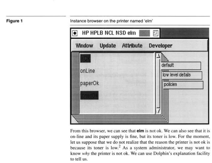
Let us pretend that we are a system administrator using Dolphin and that we are interested in finding out about our printer named 'elm'. After double-clicking on the icon representing this printer, we might be presented with a window similar to Figure 1. This browser shows (in alphabetical order) the information about elm which Dolphin has access to. The information is shown highlighted in red' if it is false.
1. Dolphin's user interfaces and the debugger interfaces developed in this the-sis frequently use of color to convey information. In this thethe-sis, we will discuss them as colors and show them in figures using shades.
Figure 1 Instance browser on the printer named 'elm'
I
HP HPLB NCL
NSD elm
From this browser, we can see that elm is not ok. We can also see that it is on-line and its paper supply is fine, but its toner is low. For the moment, let us suppose that we do not realize that the reason the printer is not ok is because its toner is low.2 As a system administrator, we may want to know why the printer is not ok. We can use Dolphin's explanation facility to tell us.
3.1.2 Getting an explanation of a problem
To get an explanation of why the printer is not considered satisfactory, we have to select isOk and ask for an explanation. Figure 2 shows the explanation we receive. By reading the red nodes, we can see that elm's toner is the problem. After changing the printer's toner, we can confirm through the browser that elm is fine.
2. In this example, the problem is obvious. However, the cause of a problem is often not easy to see. For instance, imagine that the password file on a ma-chine has its permissions set incorrectly. The effect of this might be that a user can not login. Since the problem is not with the user, looking at a user browser would show us the symptom of the problem-user can not log in- but it would not immediately show us the cause of the problem.
Dolphin's explanation of why elm is not ok.
3.1.3 Creating a new user
Our next task may be to create an account on a machine named 'netman' for a new employee. Let us suppose the employee's username is 'aybee'. We first double-click on the icon representing netman. The resulting browser (Figure 3) shows the information available about netman.
Relations such as users, which have more than one value, are shown in a box. Because we want to add a user, we double-click on the users relation. This gives us a display similar to Figure 4. From the "Object" menu, we can select "Create new HP-UX user". We are then prompted for some details about the user (Figure 5). After we enter the needed information and press "ok", a new user appears in the collection. As an administrator, that is all we see of the creation process.
An instance browser showing netman's attributes
A collection browser on the users of the machine called 'netman'
Wkndow Update
ct
Developer
Oreate
HPUXUser
adm
admin
af
afe
air
ange
anon
adf
Figure 3
Figure 4
A prompt for information used to create a user
Given the types of interaction we experience as a system administrator, Figure 6 shows our likely model of how the Dolphin prototype works.
System administrator's conceptual model of Dolphin's mechanisms
Dolphin
Prototype
Real
World
Figure 5 Figure 63.2 How Dolphin modules cooperate to help
system administrators
Since the Dolphin prototype is not implemented using magic, let us take a look at how Dolphin uses models to implement these interactions.
3.2.1 Browsing
Let us begin with the instance browser displaying information about elm.
Since Dolphin knows from previous information that elm is an HP LaserJet4, the user interface finds the HP LaserJet4 object description in its models and uses the description to decide what types of information to display. The LaserJet4 description includes basic relations describing a printer's physical status-is it on-line? is its paper ok? is its toner ok?. It also contains a derived relation describing whether or not the printer as a
whole can be considered ok.
The object description can tell the user interface only what kinds of information are available; it does not say what the values of the relations are for elm. However, the models do provide a logical definition of how to find the actual values. Using these logical descriptions is beyond the user interface's duties. Using them is the inference engine's specialty. To find the actual values it must display, the user interface asks the inference engine to try to prove the necessary logical statements. For instance, to find out if elm is on-line, the user interface asks the inference engine to prove that it is on-line.
The inference engine uses a technique called inferencing to try to support a logical statement. For instance, a basic relation describes the real world, so a basic goal (is elm on-line?) can be supported by finding a fact which states that the goal is true (elm is on-line!). The inference engine looks for facts about the real world in the fact base, a special database for storing Dolphin facts. Derived goals explain how they can be logically reduced to simpler goals. For instance, 'is elm ok?' can be simplified to 'is elm
on-line?', 'is elm's paper ok?', and 'is elm's toner ok?'. To prove a derived goal, Dolphin reduces it to basic goals which it can try to support
with facts.
We have not yet explained how facts come to be in the fact base. Suppose that the fact base had not known anything about elm. It would have needed to find facts from the real world. This is the query system's job. Its first step is to find a suitable query description to use. Part of this process involves checking that the query description's preconditions are satisfied. Since the preconditions are given as a logical expression, the inference
engine is used to check them.3 After a query has been chosen and executed, the resulting facts are stored in the fact base for later use. All of this happens in response to the system administrator's request to see information about elm, but the administrator does not have to worry about how it is done.
3.2.2 Explaining
The next thing we did as an administrator was to ask Dolphin why the printer was not ok. The explanation facility discovers the explanation by asking the inference engine to prove that elm is ok and asking it to record the way it proved this. The resulting record is then displayed for us. The "natural language" description on each node is generated from strings provided in the model.
3.2.3 Changing the real world
Our last example task was to create a new user account for 'aybee'. Once again, the user interface does not do all of the work by itself. It uses the models to decide what kinds of objects to offer in the create menu. From the models, it also decides what information to prompt for. Once it has the information, it forms a logical goal describing what it wants to change in the world. It invokes the fixer with this goal. The fixer is responsible for "fixing" the world to be the way Dolphin wants it to be. It calls on the inference engine to decide what needs to be changed and uses action descriptions to plan how to change them. Just as query descriptions have preconditions governing their use, so do action descriptions, so the fixer invokes the inference engine yet again. After the plan is made, Dolphin acts to change the world. When it is done, the affected facts are removed from the fact base so they will be updated the next time they are needed.
3. Note that during this proof, the inference engine may ask the fact base for information it does not yet have. This could, in turn, trigger the query system. Dolphin ensures that it does not enter an infinite loop.
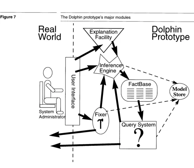
Figure 7 The Dolphin prototype's major modules I
olphin
rototype
Model
Store
/3.3 Model Development Environment
In the previous section, we looked at how the Dolphin modules cooperate to aid a system administrator. We pointed out that the system administrator
does not have to worry about this mechanism. The model development environment described in this thesis is targeted at the modeller, a person who does have to understand how the models are used. Figure 7 showed the Dolphin prototype's architecture in a modeller's terms. As we initially saw, the user interface provided for system administrators completely hides how the models are being used. This makes it insufficient for modellers, who must understand how the models are used. The model development environment is responsible for providing tools which help the modeller enter, debug, and maintain models.
We have chosen to create separate debugging tools for each of the major Dolphin systems-inferencing, querying, and fixing. Figure 8 shows the architecture of the system. The Tool Policy is used by the modeller to specify which tools she wants to use and when they should be invoked.
Model development environment
0
I
This architecture is justified from the modeller's point of view because each of the systems works fairly independently of the others. A modeller may want to debug just the logic of her derived relations. She can do this through an inference debugger without being concerned with the queries that are used. Similarly, fixes and queries can be debugged with little interest in the others. Only the inference engine is used by all of the modules. To deal with this, we embed an inference debugger within the tool which is using it. This enables the modeller to easily understand why the proofs are being done.
Creating a separate debugging tool for each system is also justified from the development point-of-view. Keeping the tools separate enabled us to develop them fairly independently. Since it is used by all of the other tools, we created the inference debugger first and it is explained in Chapter 4. The query and fixer debuggers are discussed in Chapter 6 and Chapter 5,
respectively. The tool policy is described in Chapter 7.
Figure 8
I
Chapter 4 Inference Debugger
This chapter describes the inference debugger and is organized to follow the development of a debugger. The first step in creating a debugger is understanding the system to be debugged; we must know why the system exists, when it is used, and how it operates. Next, we need to develop a conceptual model of what it does; this conceptual model will be the basis for the user's interaction with the debugger. From the conceptual model, we can determine what information we want to show to the user and what control points she should have. We can then develop techniques to gather the data required to provide the information and control to the user. Once the data has been collected, the presentation itself can be developed. Finally, when the tool has been used and examined running, we can find its weaknesses and identify future work.
The actual development of the debuggers did not flow smoothly from one stage to the next. Rather, it jumped among them and even started from scratch a few times. We found that the first time we built a debugger, we learned what the system was really doing and learned better what was needed from the tool. This chapter presents the outcome of this muddied process in terms of the clean process described above.
The primary benefit of the inference debugger developed is that it is capable of presenting a proof in an intelligible manner. As we will see, representing an inference engine's search poses two interesting problems. First, the tree developed by the inference engine's exploration of the search space is not the tree that the user wants to see. Second, the search space is multi-dimensional, and the usual simultaneous presentation of more than one dimension is confusing. We overcome the first problem by gathering information not otherwise explicitly stored by the inference engine so that we can present a more intuitive tree. We overcome the second problem by presenting only one slice through the search space at a time, exploiting the computer's ability to rapidly change the display when
the user wants to explore a new slice.
Other benefits of the tool include the fact that it is incremental and specialized. Because it is incremental, the user can explore the search each time the execution is paused. Because it is specialized to the proof debugger problem, it provides controls specialized to the inferencing problem.
4.1 What is inferencing?
Everything Dolphin does, from displaying the state of the real world to deciding how to change the world, is done with reference to the models that it is given. Because these models are given in a logical form, every use of them involves doing some kind of logical proof.
The user interface uses proofs to collect information to display to the user. Both queries and actions have to have their preconditions proved before they can be used. The action system also uses proofs to diagnose what it should change. Users are allowed to formulate their own questions for the system, and proofs are again used to find the answer.
Inferencing is a process used to prove logical statements. It is at the heart of most expert systems and the logic programming language PROLOG. Dolphin contains an inference engine which uses standard techniques, such as SLD-resolution [6], to prove logical expressions in Dolphin's models.
We can think of inferencing as finding support for a logical statement. For instance, to prove that our printer is onLine, we just have to verify with the real world that it is. Similarly, we can support the statement that the printer isOk by supporting the statements that it is online, and both its paper and toner are ok.
In logic programming theory, inferencing is done by "refutation", a kind of proof by contradiction. Rather than proving a goal, such as A is true, refutation instead demonstrates that if NOT(A) were true, there would be a contradiction. Because refutation can be described declaratively, theorists find it easier to work with than a procedural description. However, for the practical purposes of this thesis, our procedural definition will suffice. We define inferencing as "trying to find logical support for a statement". In the next section, we provide enough background on inferencing to understand this chapter. Readers interested in more information about logic programming are referred to introductory books on the subject, such as [5], and theoretical books such as [6].
4.2 How Dolphin's inference engine works
In this section we introduce the terminology we will be using and then examine how Dolphin's inference engine approaches a few simple examples.
4.2.1 Terminology
Relations describe the kinds of logical statements we can make. A relation
consists of a name and some arguments. For instance, the relation representing the name of a printer may be called name, and have two arguments-the printer and a string giving its name. In Dolphin, we write the relation as
[Printer p] name [String s]
to show the relation's name with its arguments in brackets. In this example the arguments are variables, which can represent any object of the
appropriate types (also given). In Dolphin, we only have to specify a variable's type once.
Arguments can also be instances. Instances which have a conventional representation will be written with that representation. Examples of these are shown below. For instance the integer six will be shown as
6
and the string containing the first three letters of the alphabet will be shown as
'abc'
Most Dolphin instances represent real world objects and they do not have a conventional representation. In this paper, we represent objects by writing their identifiers in bold. For example, our printer named 'elm' will be represented as elm.
Facts are instances of basic relations which state something about the real
world. A fact should not contain variables. The fact giving our printer's name is:
[elm] name ['elm']
Derived relations have definitions which give a logical relationship between their arguments. For instance, a printer's isOk relationship may be given as:
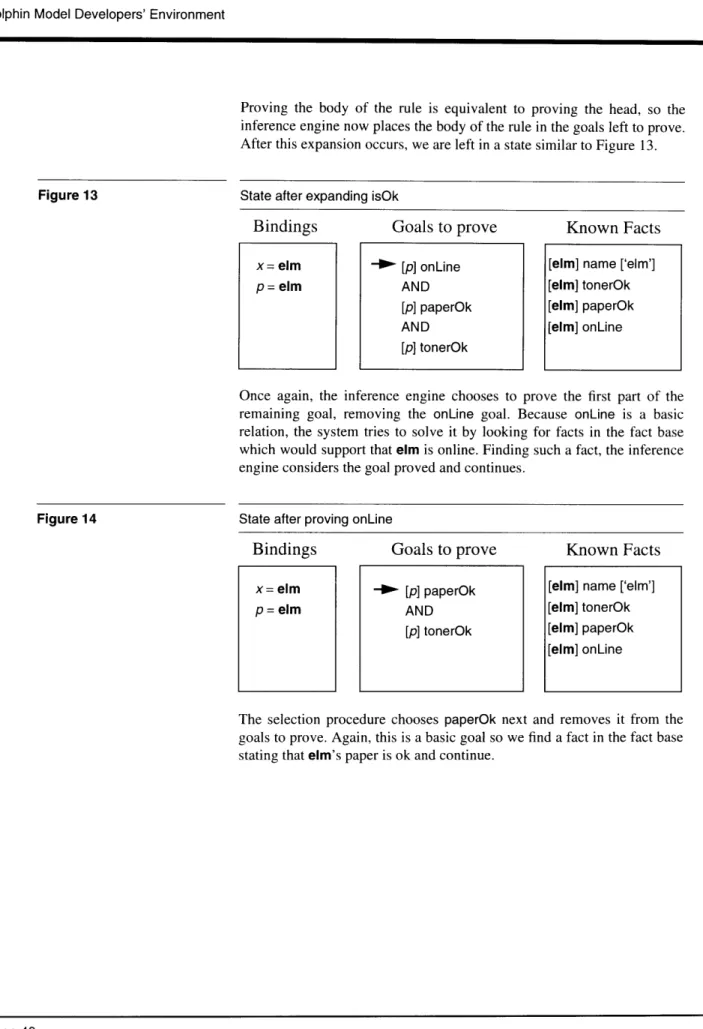
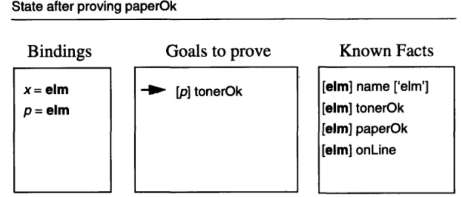
[Printer p] isOk IF [p] onLine AND [p] paperOk AND [p] tonerOk.
Goals are relations which are given to the inference engine to be proved.
They may contain both variables and instances. The following are example goals:
[elm] name ['elm'] [Printer p] name ['soseki']
Notice that a basic goal with all arguments being instances, such as
[elm] name ['elm'], differs from a similar fact, such as [elm] name ['elm'], only in interpretation.
4.2.2 A small, example model for printers
Before Dolphin can answer any questions, it needs to have one or more models loaded. Figure 9 and Figure 10 show excerpts from a model describing printers. The first basic relation can be read as "Printer p has the name n". The next three can be read as "Printer p is online", "Printer p's paper is ok", and "Printer p's toner is ok". The derived relation can be read "Printer p is ok if p is online, p's paper is ok, and p's toner is ok". Notice
that the derived relation (Figure 10) has two parts - the head, which specifies what is being defined, and the body, which gives the rule to evaluate. The basic relations only have heads; the implicit body of a basic relation is always "ask the world".
Figure 9 Some basic printer relations [Printer p] name [String n]. [Printer p] onLine. [Printer p] paperOk. [Printer p] tonerOk.
Figure 10 A derived relation for printers
[Printer p] isOk IF [p] onLine AND [p] paperOk AND [p] tonerOk.
A printer model would also provide query descriptions which would return facts corresponding to the basic attributes. It may also include action descriptions to allow Dolphin to change the printer, perhaps to turn the printer back online. Since we are concentrating on the inference process, we will ignore queries and actions in this chapter.
4.2.3 Example 1: Is the printer named 'elm' ok?
To answer this question, we can pose the following goal to the inference engine:
[Printer x] name ['elm'] AND [x] isOk
The initial state of the inference engine can be seen in Figure 11, which shows what each variable represents (bindings), a stack of the goals we are trying to prove, and the facts at our disposal.