PFC/RR-86-17 DOE/ET-51013-189 UC20D
Conceptual Design of a Commercial Tokamak Reactor using Resistive Magnets
Rene J. Leclaire, Jr.*
June 1986
Plasma Fusion Center
Massachusetts Institute of Technology Cambridge, Massachusetts 02139 USA
*present address: Los Alamos National Laboratory (S-4), Los Alamos, NM 87544
CONCEPTUAL DESIGN OF A COMMERCIAL TOKAMAK
REACTOR USING RESISTIVE MAGNETS
by
RENE JOSEPH LECLAIRE JR.
B.S., M.S., University of Lowell
1980
M.S., Nucl. E., Massachusetts Institute of Technology
1984
Submitted to the Department of Nuclear Engineering in Partial Fulfillment of the Requirements for the Degree of
DOCTOR OF SCIENCE
at theMASSACHUSETTS INSTITUTE OF TECHNOLOGY
JUNE 1986@Massachusetts
Institute of Technology, 1986Signature of Author
Department of Nuclear Engineering
May 2,1986
Certified by
Daniel R. Cohn
Thesis Supervisor
Accepted by
Chairman,
Allen F. Henry Departmental Graduate CommitteeCONCEPTUAL DESIGN OF A COMMERCIAL TOKAMAK
REACTOR USING RESISTIVE MAGNETS
by
RENE JOSEPH LECLAIRE JR.
Submitted to the Department of Nuclear Engineering
on MAY 2, 1986 in Partial Fulfillment of the
Requirements for the Degree of DOCTOR OF SCIENCE
ABSTRACT
The potential of resistive magnet tokamaks as commercial electricity
pro-ducing power plants is investigated. Parametric studies indicate that attractive
design space exists for these reactors at relatively low field (2.5
-
4.5 T),
mod-erate wall loading (3
-
4 MW/m
2) and medium to large net electric outputs
(> 600 MW,). High toroidal beta (20
-
25
%)
possible in the second regime of
plasma stability [1] may provide advantages of reduced recirculating power and
plasma current but moderate beta reactors (6
-
10
%)
remain attractive.
The cost of the increased recirculating power of resistive magnets in
compar-ison with superconducting magnets may be offset by cost savings from reduced
shielding requirements and simpler technology. In addition, the possibility of
in-corporating readily demountable toroidal field coils in resistive magnet tokamaks
combined with the reduced complexity of these designs could lead to significantly
improved availability over current fusion power plant concepts.
A conceptual design for the Resistive magnet Commercial Tokamak Reactor
(RCTR) is presented. The layout of the nuclear island is driven by
compat-ibility requirements of the demounting capability with structural and blanket
design considerations. The nuclear island is fully demountable with access to
all components within the toroidal field coils possible via simple vertical lifts.
The blanket system, segmented for vertical removal, uses a self-cooled liquid
lithium breeder/coolant with vanadium structure and an HT-9 reflector. The
first wall is also lithium cooled with a vanadium structure but is constructed
in a single, pre-tested unit for assembly and periodic replacement. Ohmic and
equilibrium field coils are located within the bore of the toroidal field coil for
improved performance.
Thesis Supervisor: Dr. Daniel R. Cohn
ACKNOWLEDGEMENTS
I would like to take this opportunity to acknowledge a number of individuals
who helped make this work possible. First, I wish to thank my advisor, Dr.
Daniel R. Cohn, for his guidance and support throughout my time at MIT. I
am also indebted to Dr. Leslie Bromberg who taught me much of what I know
about system studies.
My thanks also go to the remaining members of my thesis committee,
Profes-sor Jeff Freidberg, ProfesProfes-sor Mujid Kazimi and ProfesProfes-sor John Meyer for taking
the time to read and comment on this work. I have also had the pleasure of
interacting with a number of staff and faculty members during the course of the
thesis. In particular, I would like to acknowledge the efforts of Dr. Emmanuel
Bobrov, Professor Jeff Freidberg, Professor Mujid Kazimi, Dr. Robert Potok,
Dr. John Williams and Dr. Ted Yang.
I was fortunate to have the services of Nikolai Diatchenko for the drafting of
the engineering drawings of the conceptual design. Anatole Chernomordik did
an outstanding job on the trimetric view of the RCTR concept. My wife, Cathy,
did an excellent job on the remaining figures in the thesis.
Finally, I would like to dedicate this thesis to my wife and family. This is as
much their work as mine.
Contents
Abstract
4
Acknowledgements
4
1 Introduction
13
1.1 M otivation ... 13
1.2 Resistive versus Superconducting Magnets . . . . 14
1.3 Resistive Magnet Commercial Tokamak Reactor (RCTR) . . . . 16
1.4 Outline of the Thesis . . . . 22
2 Parametric Studies 23 2.1 Introduction . . . . 23
2.2 Approach to Parametric Surveys . . . . 25
2.3 The Parametric Code . . . . 27
2.4 Trade-off Studies . . . . 35
2.4.1 High Beta Cases . . . . 36
2.4.2 Moderate Beta Reactors . . . . 43
2.4.3 Other Trade-offs . . . . 50
2.4.4 Multiplexing . . . . 54
2.4.5 Resistive Vs. Superconducting Magnet Tokamak Cost Comparison . . . . 56
2.5 Illustrative Designs . . . . 60
2.6 Summ ary . . . . 64
3 Demountable Coil System
66
3.1 Introduction . . . . 663.2 General Considerations . . . . 67
3.2.1 TF Coil Configuration . . . . 67
3.2.2 Joints . . . . 68
3.2.3 TF Coil Support . . . .. .. . . . .. 71
3.2.4 Integration With Other Systems . . . . 74
3.3 Reference Demountable Concept . . . . 78
3.4 Assembly and Maintenance . . . . 84
3.5 TF Coil Stress Analysis . . . . 92
3.5.1 In-plane Analysis . . . . 93
3.5.2 Out-of-Plane Analysis . . . . 97
3.5.3 Stress Analysis Results . . . 100
3.6 Internal vs External Poloidal Field Coils . . . 102
3.7 Summary . . . 104
4 Blanket/First Wall System 4.1 Introduction . . . . 4.2 General Considerations for the Design . . . . 4.2.1 Breeding Materials . . . . 4.2.2 Structural Materials . . . . 4.2.3 Reflector/Shield Composition . . . . 4.2.4 First Wall Materials . . . . 4.2.5 Blanket/First Wall Configuration . . . . 4.3 Blanket/First Wall Reference Concept . . . . 4.4 Neutronics Analysis . . . . 4.4.1 Calculational Method . . . . 4.4.2 Reflector Material Comparison . . . . 4.4.3 Blanket Thickness Trade-offs . . . . 4.4.4 Reflector Thickness Tradeoffs . . . . 4.4.5 Neutronics Summary . . . . 4.5 Supporting Analysis . . . . 4.5.1 MHD Pumping Losses . . . . 4.5.2 Stress Analysis . . . . 4.5.3 4.5.4 Blanket/First Wall System Analysis Code Supporting Analysis Results . . . . 106 . . . . 106 . . . . 106 . . . . 107 108 . . . . 109 . . . . 110 . . . . 110 . . . . 112 . . . . 118 . . . . 119 . . . . 121 . . . . 123 . . . . 125 . . . . 128 . . . . 128 .. 130 . . . . 132 . . . . 134 . . . . 137
4.6 Summary ...
5 Accessible Beta and Tokamak Reactor Design
5.1 Introduction... ...
5.2 General Considerations ...
5.2.1 Kink Mode Stability . . . .
5.2.2 Ballooning Mode Stability . . . .
5.2.3 Beta Limit Mechanisms . . . .
5.3 Conventional Beta Limits . . . .
5.3.1 Theoretical and Experimental Results . .
5.3.2 Discussion . . . .
5.3.3 Summary . . . . 5.4 Second Stability Beta . . . . 5.5 Summary . . . . . . . 143 144 . . . . 144 . . . 145 . . . 146 . . . 147 . . . 148 . . . 149 . . . 149 . . . 154 . . . 159 . . . 161 . . . 169
6 Summary, Conclusions and Recommendations
6.1
Introduction ...
...
6.2 RCTR Parametric Studies ... ... 6.3 Resistive Magnet Commercial Tokamak Reactor (RCTR) Reference Design . . . . 6.3.1 General Characteristics . . . . 6.3.2 Toroidal Field Coil . . . . 6.3.3 Nuclear Island/Demountability . . . . 6.3.4 Assembly and Maintenance . . . . 6.3.5 Blanket/First Wall . . . . 6.4 Conclusions . . . . 6.5 Recommendations . . . .. 171 171 173 179 179 181 184 185 188 193 194 A Parametric Code RTPAC 195 A.1 Introduction . . . 195A.2 Interpreting Macsyma Programming . . . 195
A.3 RTPAC Code Listing . . . 197 218 218
B Costing Code
B.2 Costing Code Listing . . . 218
C Blanket Analysis Codes
C.1 Introduction ...
C.2 Sample Input File for TRANSX . .
C.3 Sample Input File for ONEDANT
C.4 Blanket Analysis Code . . . .
229 . . . 229 . . . . 229
. . . . 233 .
List of Figures
1.1 Trimetric View of RCTR ... ... 17
1.2 Plan View of RCTR Concept ... ... 20
1.3 Top View of RCTR Concept ... 21
2.1 Flow Diagram for Parametric Code RTPAC ... ... 28
2.2 RCTR Coil Geometry ... 33
2.3 Second Stability vs Wall Load, 1200 MWe, d = 24%, k = 1.8, A = 5 . . . ..- . . . ..- -.-. . - . . . . 37
2.4 Second Stability Net Power Scan, 3 MW/M 2 , A = 5, k = 1.8, 3 = 24% . . . . . . . .. .. . . . . . . . . 39
2.5 Second Stability Beta Scan, 1200 MW,, 3 MW/m 2, A = 5, k = 1.8 42 2.6 First Stability Wall Load Scan, 1200 MWe, A = 3, k = 1.8, ) = 7.3% 44 2.7 First Stability Net Power Scan, 3 MW/m2, A = 3, k = 1.8,)4 = 7.3% 46 2.8 First Stability Aspect Ratio Scan, 1200 MWe, 3 MW/M2, 3 = 7.3% 47 2.9 First Stability Beta Elongation Scan, 1200 MWe, 3 MW/m 2, A = 3 49 2.10 First Stability Beta Scan, 1200 MWe, 3 MW/M2, A = 3, k = 1.8 51 2.11 Cost of Electricity vs Recirculating Power Fraction . . . . 61
3.1 Major TF Coil Joint Types . . . . .. . . . . . . . 70
3.2 MULTILAM Louver Geometry . . . . 71
3.3 Keyed Joint Concept . . . . 73
3.4 Locking Ring Joint Concept . .. .. . .. . . . . . 75
3.5 Cap Supported Joint Concept . . . . . . . . . 76
3.6 Out-of-Plane Support Using Wedges . . . . 77
3.7 Top View of RCTR Nuclear Island . . .. .. . . . . . 81
3.8 Cutaway View of RCTR Nuclear Island . . . . 82
3.10 Steps 3 and 4 of RCTR Assembly Procedure . . . . 87
3.11 Steps 5 and 6 of RCTR Assembly Procedure . . . . 88
3.12 Steps 7 and 8 of RCTR Assembly Procedure . . . . 89
3.13 Steps 9 and 10 of RCTR Assembly Procedure . . . . 90
3.14 Steps 11 and 12 of RCTR Assembly Procedure . . . . 91
3.15 Moment Distribution in TF Coil . . . . 96
3.16 In-Plane Forces on the Toroidal Field Coil . . . 100
3.17 Schematic Comparison of Internal and External EF Systems, P, =
1200 MWe, 3 = 7 %, P = 4 MW/m
2, Bo = 4.1 T . . . 103
3.18 Average Overturning Force Per TF Plate . . . 105
4.1 Blanket/First Wall Cross-Section . . . 113
4.2 Blanket Diagram Showing Flow Patterns . . . 114
4.3 First Wall Cross-Section . . . 117
4.4 ONEDANT Calculational Geometry . . . 120
4.5 Energy Multiplication Factor and Tritium Breeding Ratio versus Blanket Thickness . . . . 124
4.6 Coil Lifetime versus Blanket Thickness . . . 126
4.7 Energy Multiplication Factor and Tritium Breeding Ratio versus Reflector Thickness . . . . 127
4.8 Coil Lifetime versus Blanket Thickness . . . 129
4.9 Geometry Used by Blanket System Code . . . 135
4.10 Lithium Flow Parameters versus Blanket Thickness . . . 139
4.11 Pressure Drop versus Reflector Lithium Flow Cross-Section . . . 140
4.12 Lithium Pressure Drop versus Wall Loading . . . 142
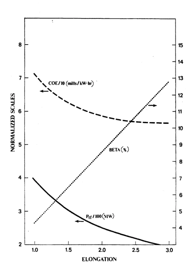
5.1 Beta vs Elongation for Three Approaches To The Use of the Doublet-III Beta Scaling . . . . 158
5.2 Second Stability Beta Accessibility versus Indentation . . . 164
5.3 Bean Geometry for Second Stability Investigations . . . 165
5.4 Second Stability Beta Accessibility versus Safety Factor . . . 166
6.1 Trimetric View of RCTR Conceptual Design . . . 180
6.2 Plan View of RCTR Concept . . . 182
List of Tables
1.1 RCTR Illustrative Case ...
2.1 Parameters Characterizing Resistive Tokamaks . . . . 2.2 Major Inputs Required for RTPAC . . . .
2.3 Major Cost Accounts . . . . 2.4 Second Stability vs Burntime, 1200 MWe, 3 MW/m2, k = 1.8,
0 = 24% . . . .
2.5 First Stability vs Burntime, 1200 MWe, 3 MW/m 2, k = 1.8,
,3 = 7.3% . . . .
2.6 Impact of Improved Thermal Efficiency . . . . 2.7 Multiplexing Cost Comparison . . . .
2.8 Cost Comparison of Resistive and Superconducting Tokamaks . .
2.9 RCTR Illustrative Concepts . . . . 3.1 3.2 3.3 3.4 4.1 4.2 4.3 4.4 4.5
Base Parameters for Demountable Design . . . . Demountable Coil Characteristics . . . . Toroidal Field Coil Helium Cooling . . . . RCTR Support Structure . . . . Reference Blanket Parameters . . . . Reference First Wall Parameters . . . .
Reflector Material Comparison . . . . Reference Input Parameters for Blanket Analysis . . . . . Insulated vs Uninsulated Lithium Channels . . . .
5.1 Beta Scaling Comparison versus ...
5.2 Numerical Comparison of q* and q (D-I1I Form) . . . .
. . . . 79 . . . . 83 . . . . 84 . . . . 101 . . . . 116 . . . . 118 . . . . 122 . . . . 137 . . . . 138 155 159 16 24 29 34 52 52 53 55 59 62
5.3 Impact of Beta Scaling Choice on RCTR Parameters, Pt,, =
1200 MWe, P, = 3 MW/M2, A = 3, k = 1.8 . . . 160
5.4 Impact of q* Choice on RCTR Parameters, Pt,e = 1200 MWe, P = 3 MW/m 2, A = 3, k = 1.8 . . . 160
5.5 Impact of Reduced Fusion Power Density with Second Stability Physics on Reactor Parameters . . . .. 169
6.1 RCTR Illustrative Concepts . . . 177
6.2 Demountable Coil Characteristics . . . 183
6.3 Toroidal Field Coil Helium Cooling . . . 184
6.4 Reference Blanket Parameters . . . 191
Chapter 1
Introduction
1.1
Motivation
One of the most important questions facing the fusion community today con-cerns the attractiveness of tokamaks as commercial electricity producing reac-tors. Critics claim that tokamak geometry and components are too complex, its cost too high and that required maintenance on these devices will be either dif-ficult or impossible. Indeed, a major effort is underway to identify innovations which may significantly improve the tokamak concept as a commercial power producer [2]. The objective of this thesis is to explore the potential of tokamaks using resistive magnets as commercial electricity producing reactors. This al-ternative to superconducting magnet designs combined with other innovations or extrapolations in engineering and physics may provide the fusion community with a significantly more attractive tokamak concept than STARFIRE
[3],
the most recent vision of the commercial fusion future.Until recently, resistive magnet tokamaks had only been considered as ex-perimental devices [4], ignition machines [5] or as commercial devices in largely non-electricity producing applications such as the production of copious neu-trons and process heat [6,7]. These machines are generally characterized by compact size, high power density and high magnetic field. These characteristics are ideal for such near term applications when low cost and high performance are the primary concerns. The major drawback of resistive magnets, high dissi-pated power due to joule heating in the conductor, can largely be overlooked in these types of applications.
inap-propriate for resistive magnets due to the relatively large recirculating power requirements. We will show that high field, high wall loading and large recircu-lating power need not characterized these designs and identify attractive options for resistive magnet tokamaks. Low toroidal field more naturally characterizes commercial resistive magnet tokamaks because the minimum dissipated power in the toroidal field (TF) coils is desired. Recirculating power can be further reduced through design by minimizing the distance between the plasma and the TF coil, maximizing the conductor filling fraction, and placing the poloidal field (PF) coils within the bore of the TF coil.
The concepts presented herein for the Resistive magnet Commercial Toka-mak Reactor (RCTR) will explore the advantages of resistive magnets such as reduced complexity and demountability (dismantling of the TF coil) as well as incorporate other innovations such as high beta possible with plasmas operating in the so-called second region of stability [1]. We will attempt to optimize the concept, taking into account all major systems and give special attention to some of the major components, developments in which could lead to a significantly improved reactor concept.
1.2
Resistive versus Superconducting Magnets
The major disadvantage of resistive or normal magnets in comparison to su-perconducting magnets is the relatively large dissipated power associated with them. The refrigeration power required to maintain the superconducting envi-ronment of - 4 K in a superconducting magnet is generally considerably less than the joule losses in a normal magnet. This is an important consideration for commercial electricity producing reactors since a larger recirculating power requirement means that less power is available for sale off site. However, we will show that the resistive power of the magnets can be minimized in a number of ways and that recirculating power does not fundamentally limit the use of resis-tive magnet tokamaks in pure fusion (electricity production only) applications. In addition, resistive magnets offer a number of advantages in comparison to the superconducting variety in the areas of durability, complexity and maintenance. Resistive magnets in commercial applications tend to operate at relatively low stresses because the build of the magnet is made large to minimize the
current density and dissipated power. Thus, operation in both the steady state and pulsed modes is not a problem from the point of view of approaching the yield stress or endurance limit, respectively, for the materials of interest. For superconducting magnets, the low ductility at operating temperature implies a large structure to decrease stresses in the pulsed mode. In steady state mode, superconducting magnets generally operate at higher stress because of smaller magnet builds and higher peak magnetic fields. In addition, the power required to drive steady state current is typically similar to that required by the TF coils in a resistive magnet device.
Normal magnets require less shielding than the superconducting variety and thus can be more compact. This can lead to lower costs and higher system power density in the resistive device for the same wall loading. Resistive magnets are less sensitive to neutron streaming and are more tolerant to local hot spots.
They are also less sensitive to changing magnetic fields.
Resistive magnets are generally less complex than superconducting magnets, consisting basically of sheets of copper with no requirements for a cryogenic environment. This can lead to a more reliable and available system and perhaps to a lower overall cost. These factors are particularly important in light of the fact that many of the weaknesses of present commercial tokamak designs are associated with either cost or reliability and availability.
A major advantage associated with resistive coils is the possibility of taking
apart or demounting the coils with relatively simple designs. Concepts have been proposed for demountable superconducting coils but are not being consid-ered presently in major tokamak studies due to complexities involved with the large number of filaments and the cryogenic environment. In contrast, joints in resistive coils are already being used in a number of devices [8,9] and are being considered even in compact, high field applications [10].
Demountability of the TF coils offers significant advantages to tokamak de-sign. Readily demountable coils may facilitate maintenance with a resulting increase in availability. Furthermore, demountable coils allow the use of various coils inside the TF coil including equilibrium field (EF), ohmic field (OH) and bean shaping coils (for possible high beta application). Placing coils within the TF coil can significantly reduce the resistive power of EF coils, increase the at-tractiveness of the use of a magnetic divertor, reduce the overturning moment
Net Electric Power, MW, 1200 Wall Loading, MW/m 2 3 Toroidal Beta, % 24 Major Radius, m 7.5 Aspect Ratio 5 Field on Axis, T 2.4 Plasma Current, MA 4.7
Nuclear Island Weight, ktonnes 14.2
Thermal Power, MW 3380
TF Dissipated Power, MW, 108
Total Recirculating Power, MW, 228
Direct Cost, $M 2065
Capital Cost, $M 3680
Cost of Electricity, mills/kW.hr 45.4 Recirc. Power Fraction 0.16
Mass Utilization, T/MWth 4.2 Eng. Power Density, MWth/m 3
1.2
Table 1.1: RCTR Illustrative Case on the TF and allow the achievement of higher elongations.
Thus, despite relatively high recirculating power, resistive magnets may offer significant advantages over superconductors in commercial electricity producing applications from the points of view of complexity, maintenance and cost.
1.3
Resistive Magnet Commercial Tokamak
Reactor (RCTR)
Parametric and systems analysis of tokamaks using resistive magnets have iden-tified a number of attractive options for RCTR. Major parameters characterizing an illustrative case for these devices is shown in table 1.1. A trimetric view of the RCTR concept is shown in figure 1.1. The case shown assumes operation in the second regime of plasma stability. Discussed in more detail in chapter five, the second regime requires careful control of the plasma pressure profiles and operation at high aspect ratio but may provide access to very high beta. The aspect ratio of five and choices of net electric power output, P,,,,, = 1200
MW', and wall loading of Pa 11 = 3 MW/m2 leads to a major radius of 7.5 m. 0 = 24% is achieved assuming operation in the second stable region.
t0
The high beta results in a very modest magnetic field on the axis of the plasma of 2.4 T. As a result of the use of second stability at high aspect ratio, the plasma current is also modest at 4.7 MA. Very long pulses driven by an OH coil internal to the TF coil are possible. The design of table 1.1 is capable of six hour pulses although pulses approaching one day in length are possible with similar machines.
The TF coil is optimized for lowest cost by trading off weight against dis-sipated power. The power required by the TF coil is 108 MW. Combining the power requirements for blanket pumping, balance of plant and other auxiliaries, the total auxiliary power requirement is 228 MW. This is comparable to the recirculating power requirements of STARFIRE, including the power needed to drive the steady state RF current. All magnet coils are constructed of copper and insulated with polyimides. Ceramic insulation may be used in areas of high-est radiation dose. The coils are cooled with helium flowing through channels formed during their casting.
The weight of the nuclear island (all components within the TF boundary including the TF and external support structure) is 14.2 ktonnes including 8.6 ktonnes for the coils. This compares quite favorably with STARFIRE (- 26 ktonnes) because of the compact nature of the nuclear island. Also, shielding is not required between the plasma and the coils and the TF coils serve as an effective biological shield.
Two figures of merit, engineering power density
(EPD)
and mass utilization factor (MU) are also shown in table 1.1 where:Total MWth
Volume enclosed by the TF coils and
MU
= Weight of nuclear island (1.2)Total MWth
The high engineering power density (1.2 versus 0.3 for STARFIRE) and favor-able mass utilization (4.2 versus 6.7 for STARFIRE) shown illustrate an asset for resistive magnet designs; the capability for high system power density at moderate wall loading and the compactness of the nuclear island (leading to lower weight and cost).
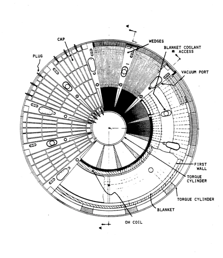
An engineering drawing of the plan view of RCTR is shown in figure 1.2. The TF coil is of frame type and is demountable with lap joints in each of the four corners. The inboard leg of the toroidal field coil is unusually large to minimize the resistive power. Note that the demountability allows placement of the ohmic and equilibrium field coils inside the TF bore. The cooling channel arrangement, is also shown.
The blanket is a self-cooled liquid lithium design using a vanadium struc-ture and a ferritic steel (HT-9) reflector. A separate shield is not necessary. The blanket is divided into twelve sections toroidally and is divided along the midplane, allowing the blanket sectors to be removed independently of the first wall. The lithium coolant enters through vertical ports and flows poloidally at moderate velocity to minimize the MHD pressure drop.
Lithium flows toroidally in the vanadium first wall at relatively high velocity
(a
1 m/s) to provide the required cooling at acceptable pressure drops. The firstwall is designed as a single piece which can be removed as such when necessary to avoid the breaking of vacuum during assembly and repair operations. The use of a self-pumped first wall or limiter [11] is envisioned for impurity control.
External structures are designed to support the in-plane vertical bursting forces on the TF coils and the overturning forces created by the interaction of the poloidal field and toroidal current. This structure consists of inner and outer steel cylinders tied together by twelve steel flanges separating the TF coil packs. Wedge shaped steel caps sit above the coil packs and are secured to both inner and outer cylinders with a number of steel plugs. These structures are shown in a top view in figure 1.3. The vertical forces are transferred from the steel caps to the cylinders by the steel plugs. The overturning forces are taken by the continuous structure formed by the steel caps, flanges and inner and outer cylinders.
The nuclear island is designed with maintenance as a major priority. All components are removable with simple vertical lifts without the need for break-ing of welds and with as few bolts as possible. Assembly of the nuclear island is illustrated in figures 3.9 through 3.14 of chapter 3 (after page 84). The lower sections of the TF coils and wedges are assembled first on top of the lower cap and around the inner torque cylinder. This is followed by the placement of the inner leg section of the TF and wedges and the insertion of the OH coils. Then
U 0 U H 0 H-~ ~ ~ N. r1~ -- F:. I-- -~
BLANKET COOLANT SACCESS VACUUM PORT FIRST TORQUE CYLINDER BLANKET OH COIL
the blanket sectors can be lowered in followed by the first wall which is inserted as a single piece (already vacuum-tested). With the upper blanket sectors in place, the outer sections of the TF coil and wedges are inserted. The outer torque cylinder then drops in around the entire assembly. Final assembly takes place with the insertion of the upper TF coil and wedge sections followed by the upper caps and plugs.
Repair and replacement of components takes place in the reverse of the order shown in the diagrams. Note that sections of the TF coil and blanket can be removed with the removal of a single section of plugs and cap but removal of the first wall and other toroidally continuous structures requires removal of the entire top structure. Some repairs may be possible through the six vertical ports penetrating to the vacuum chamber.
Several viable options have been identified for RCTR although the basic design for the coils, blanket/first wall and maintenance scheme remains common to all. These options include low beta designs in the event operation in the second stability regime does not prove practical, the use of aluminum TF coils, and operation at relatively low wall loading
(-:
1 MW/m 2).1.4
Outline of the Thesis
Exploring parameter space to identify the most attractive options for commercial electricity producing reactors using resistive magnets was a major emphasis of the thesis. Chapter two describes a code developed to make this exploration and details the results and conclusions of each of the tradeoffs made. The next two chapters discuss systems aspects and engineering for some of the components which are of key importance in the design. Chapter three covers maintenance, detailing the design for the demountable TF coils. Chapter four discusses the blanket and first wall design. In Chapter five, the issue of beta limits in tokamak design is explored. The impact of the uncertainty in beta on reactor design is evaluated and recommendations are made for the sensible use of present scal-ings in reactor design codes. Finally, in chapter six, results, conclusions and recommendations for further work are presented.
Chapter 2
Parametric Studies
2.1
Introduction
The case presented in chapter one characterizing an illustrative concept for RCTR is just one of an infinite variety of designs possible. The purpose of this chapter is to present the methodology used to find the most attractive con-cepts given the starting point we have selected. The starting point is a tokamak design using resistive magnets because we perceive that such a concept may have unique characteristics which could lead to an improved commercial fusion reac-tor. We wish also to emphasize the issues of complexity, maintenance and cost since these are perceived as areas of importance to the eventual realization of commercial fusion. Given this starting point, parameters such as power output, magnetic field, major radius and many others must be selected self-consistently to arrive at the best possible illustrative concepts which then form the basis for more detailed analysis.
A partial list of the parameters of interest characterizing an electricity
pro-ducing tokamak using resistive magnets is shown in table 2.1. General comments on the approach used to reduce these unknowns to a manageable number in a manner leading to the identification of illustrative concepts for RCTR are made in section 2.2. This approach is incorporated into a zero dimensional computer code which is discussed in section 2.3. Section 2.4 summarizes the results of the parametric trade-offs. The choice of illustrative designs is discussed in section
Parameter
Net Electric Power Neutron Wall Loading Major Radius
Minor Radius Aspect Ratio Elongation Toroidal Beta
Weight, Nuclear Island Magnetic Field on Axis Plasma Current
Fusion Power
Total Thermal Power TF Coil Dissipated Power Total Auxiliary Requirement Burntime (Pulse Length) Capital Cost
Cost of Electricity Magnet Coil Stress Stored Energy Units MW,
M1lW/m
2 m mI Tonnes Tesla Amperes Megawatts (MW) MWe MW, MW, Hours Billions ($B) mills/kW-hr MPa Joules (GJ)Table 2.1: Parameters Characterizing Resistive Tokamaks Symbol P~t,e Pw
R
a
A
k
w
W
Bo
I,
Pf
Pth PTF P, rbC
COE
E-2.2
Approach to Parametric Surveys
There are almost as many ways to approach the parametric studies as there are parameters to be studied. The philosophy used here is to reduce the number of major inputs to a minimum and look at. the sensitivity of the results to these inputs. These major input parameters were selected to be as well characterized as possible in the sense that their allowable or desirable range of values is well known and/or set by external constraints such as engineering limits. Additional comments describing 'major' input parameters and the approach used to select them will emerge naturally as each input and its impact on the trade-offs is discussed.
Fusion power, Pf, and neutron wall loading, P, were considered from the beginning as possible inputs for the parametric analysis because they each form a good basis of comparison for different reactors and reactor concepts and their range of values is relatively well characterized. Fusion power represents the fundamental desirable outcome of building a fusion device while wall loading is a fundamental driver of the size, cost and feasibility of the machine. The thermal power requirements of present day power reactors and the engineer-ing constraints on first wall lifetime help to characterize these parameters with considerations outside their impact on the parametric trade-offs.
In addition, the specification of fusion power and wall loading significantly reduces the number of unknowns in the problem because their ratio is only a function of geometry. Specifically;
Pf-
572 R 2(2.1)
P, 2
where a is the minor radius, R the major radius and k is the elongation. We choose to treat elongation as an input (and explore the sensitivity of the results to this choice) so that this ratio is only a function of a and R.
However, fusion power can be a deceiving basis of comparison with resistive magnet tokamaks because of the potentially large recirculating power require-ments. Thus, the net electric power output, Pt,,, of the fusion plant (the useful power output after accounting for recirculating power requirements) is a supe-rior basis of comparison and a better choice for an input parameter. Pt,e can
be written as:
Prwt,e = 77thMPf - P, (2.2)
where 77,h is the thermal conversion efficiency, M is blanket energy multiplication and P, is the total recirculating power requirement including magnets, coolant pumping and other auxiliaries.
For a given choice of blanket design, M and gp. are well characterized. How-ever, we have introduced an additional unknown in P, which cannot be de-termined before the geometry of the device is known. Therefore, a guess for the recirculating power is made which leads to the determination of a reactor geometry (in a manner described below). Once the geometry is known, the recirculating power for that specific geometry can be determined and the net electric power found. The guess is then modified in an iterative process until
the desired Pt,, is obtained.
Next, we choose to treat aspect ratio (A =) as an input parameter. This choice is also a powerful lever in reducing the unknowns and is surprisingly well characterized for these designs. For reactors operating in the second regime of plasma stability, high aspect ratios of 5 to 6 are required for stability while early parametric studies showed that low aspect ratio (about 3) was desirable for reactors in the first stability regime. This will be discussed in greater detail in section 2.4. The choices of P,, Po±t,e, k, and A now determine the minor and major radius of the device uniquely.
The final major input choice is the beta scaling desired. For operation in the second regime of stability, maximum beta may be set by plasma equilibrium limits. Empirical and theoretical limits exist for maximum beta in the first region of plasma stability. These limits will be presented in more detail in chapter 5 but they are generally found as a function of elongation, aspect ratio, plasma triangularity and plasma safety factor. Thus, for reasonable choices of plasma triangularity and safety factor, beta is determined and the rest of the parameters characterizing the tokamak fall into place.
Magnetic field on the axis of the plasma, B0, is now determined from
ex-pressions for either fusion power or wall loading. This determines the required plasma current and ohmic system requirements. Then the toroidal field coil is determined based on an optimization of weight and cost to be discussed in the next section. Finally, the remainder of the system's characteristics can be
determined including stored energies, EF requirements, stresses, weights and costs.
The methodology can be represented as a progression from the plasma axis outwards. Choices of wall loading, net electric power, aspect ratio and beta scaling essentially determine the plasma requirements and geometry which then determine the OH and EF requirements. Adding requirements for the blanket design then determines the bore of the TF coil. Finally, the TF coil is optimized and the remaining characteristics of the device are evaluated.
2.3
The Parametric Code
The methodology of section 2.2 has been incorporated into a computer code
RTPA C written in the MACSYMA programming language. The code evolved
from a parametric code written by L. Bromberg [12] to investigate resistive magnet ignition devices. However, the optimization and characterization of a commercial device is quite different from that of an ignition machine and the codes are left with relatively little in common. A listing of the code is included in Appendix A.
MACSYMA is a very interactive programming language within a symbolic program written in LISP. It is quite similar to FORTRAN in most respects although more powerful and much more interactive in nature. Details on how MACSYMA can be interpreted and converted to FORTRAN are contained in Appendix A.
A list of the major inputs required by RTPAC is shown in Table 2.2. Also
indicated in table 2.2 are the determining factors for these inputs. Note that the choice of most of the inputs does not narrow the focus of the parametric study but are the result of external constraints and choices. For instance, the choice of a blanket option (with neutronics and other analysis of that option) determine blanket energy multiplication, thermal efficiency, and the dimensions of the blanket/shield/first wall regions.
A flow diagram for RTPAC is shown in Figure 2.1. The first step of the
calculation is to find the average toroidal beta consistent with the choice of beta scaling. In the second stability region of plasma stability, the maximum beta is set by MHD equilibrium limits [14] while experimental [15] and theoretical [16]
INPUT Pnet,e, Pw, A, K CALCULATE B, a, R B0, Ip DETERMINE POLOIDAL FIELD REQUIREMENTS INTERUNAL OR EXTER>NAL EFOH ? DETERMINE POLOIDAL FIELD COILS DETERMINE TF BORE AND
OPTIMUM
TF SIZE ADJUST RECIRCULATING POWER GUESS DE TF RI POWE I NET NO POWER COS ANA TERMINE POWER, EACTOR R BALANCE S - POWER - INPUT YESFigure 2.1: Flow Diagram for Parametric Code RTPAC
TING LYS'S
Table 2.2: Major Inputs Required for RTPAC
formulations exist for beta limits in the first stability region. More detail on accessible beta regimes is contained in chapter five. The code assumes operation at ninety percent of the maximum volume average beta indicated by the selected scaling.
Choices for net electric power, wall loading, aspect ratio, and elongation combined with a guess for the recirculating power then determine the fusion power and the major and minor radii. Then from the expression for wall loading;
P. = -CO2B 1a 1 2 (2.3)
5 2k2
the magnetic field on the axis of the plasma can be determined. C is a constant depending on the plasma temperature and profiles which is calculated assuming the plasma is ignited and operation at the maximum of the fusion power density versus temperature (C) is desired. However, for typical RCTR parameters, operation at the maximum in C results in a violation the Murakami limit on average density [17]:
B0
1.5=B1.5 * x 1020 (2.4)
n~ -1.5Roq*
where all units are in MKS and q* is as defined below. The difference is about a factor of two for moderate beta devices which could be compensated for by the
Input
net electric power wall loading aspect ratio elongation beta
plasma safety factor blanket multiplication tritium breeding blanket thicknesses burnt ime
material properties material unit costs availability cost factors
Determination
sensitivity study sensitivity study sensitivity study sensitivity study scaling law MHD theory neutronics neutronics blanket analysis sensitivity study material data basecosting literature sensitivity study
uncertainty in the limit itself (which may improve for auxiliary and alpha heated plasmas [18]) and/or by a moderate increase in magnetic field to make up for operation at the higher temperature (and lower C) demanded by the Murakami limit. With high beta devices the difference could be closer to a factor of 5 - 10
and Murakami could possibly represent a more fundamental limit.
The plasma current., Ip, can be determined from an expression for the plasma safety factor, q* [14];
5a
2B
q-
=
k.
(2.5)2RIp
Next, the ohmic system can be evaluated. The analysis for ohmic and equilib-rium field system requirements is similar to the development used in Bromberg's code [12] with options added to allow placement internal to the toroidal field coil and to extend the results to higher elongations. The resistive volt second re-quirement is calculated for relatively impurity free plasmas and including finite aspect ratio corrections [19]. Plasma burntime is treated as an input. Inductive volt second requirements for the EF system are found using a numerical fit to the results of a series of large-scale plasma equilibrium code runs (see below). An allowance is also made for start-up volt-second requirements.
Once the requirements are determined, the ohmic coil can be sized using a stress constraint and the placement of the coil with respect to the TF coil. With the plasma geometry determined and a reasonable plasma scrape-off distance selected, an allowance for blanket, first wall, and reflector/shield components (see chapter 4) defines the inner edge of the ohmic coil if it is internal to the TF coil. The code also allows for an ohmic coil external to the TF bore and the use of RF current drive or RF assisted start-up. However, this investigation emphasizes the OH driven current option with the OH placed inside the TF bore.
Since the plasma chamber, blanket envelope and OH coil have been deter-mined, the inner bore of the TF coil is now defined. The total TF current required is determined by;
B l, (2.6)
where py, is the permeability of free space. However, the build (width) of the TF coil still needs to be found. Typically, this is done by imposing a stress constraint and operating at some maximum allowable stress at the inboard leg.
However, this is inappropriate in light of the importance of the dissipated power of the TF coil in an electricity producing device. Therefore, we optimize the TF coil with dissipated power and weight rather than high performance in mind.
The optimization is done for a frame-type rather than a bitter (circular or oval) coil because of demountability constraints discussed in chapter 3. The widths of the inner, outer and horizontal legs of the coil are varied independently using an algorithm which attempts to minimize the cost of the coil as a function of its weight and dissipated power. The inner leg of the TF coil is optimized simply for minimum dissipated power because this region of low cross-section is the site of a relatively large fraction of the dissipated power and a relatively small fraction of the weight and cost. The code allows the inner leg to grow in size until a further increase in bulk no longer results in an appreciable decrease in dissipated power.
In order to find the dimensions of the remaining TF legs, it is first necessary to find the volume and dissipated power for a frame coil. These are straight-forward calculations for this simple geometry with the results:
V
= 47rf
0AR(Rh
+ At)+ 21rfiRa
2(2f'
- f' 2)(Rh + At)+47rf
0AtRt(Rb
-
Rt) + 2?r(Rt
2- R
)Af
4xPo(Rh+At) 8wPo(Rh+Al) tj RtAf, + R 2(2f'-f'2)f.(2.8)
4jPo(Rb-R)+ 47rPoLog( j) RoB2P&
=B2,
2 2 (2.9)P
2A0,
0 2where
f,
andfj
are the volumetric fractions of copper in the outer and inner sections, respectively,f'
= '-, 71, is the resistivity of the conductor, B0 is themagnetic field at the axis of the plasma and the remaining geometrical param-eters are as defined in figure 2.2.
The TF coil is sized for minimum cost assuming that the cost of electricity can be written in the form:
CO E
=Pt f
V
Q1
+
a2-(2.10)
COEo
Pto
V
where COEO, Ptfo and V are normalizations and the alphas are constants. This function is minimized by taking partial derivatives with respect to the widths of the horizontal and outer TF legs, A, and A0. For the simplified case where
the contributions from the inner leg and the corners are neglected, the result for the widths at minimal cost of electricity is:
a
1VoPo
(Ao)min =P
2 ., (2.11)a2PoRt
2f02 2Po(RbRt) + 2Polg( ) Rt J. *(.22f.R,(Rb
-Rt) + (Rt
2 -R
2)f(The constants a, and a2 are determined by fitting equation 2.10 to the results of a series of paramnetrics which find the cost of electricity as a function of variations in the resistive power and weight of the TF coils.
A routine is also included to estimate the equilibrium field (EF) system.
Usually, this type of calculation is quite involved and makes use of a large plasma equilibrium code such as NQX
[20].
Here we make use of a routine utilized in previous MIT studies [21] which uses a numerical fit to the results of a series ofNQX equilibrium calculations. This method, although approximate and limited
in scope, is useful for parametric studies. Given geometry, plasma safety factor and toroidal field, the routines yields estimates for the inductive volt second contribution of the EF system and the currents in four (two above and below the midplane) EF coils.
At this point, all major systems have been determined and the code cal-culates the remaining characteristics of the device. Stresses in the coils and support structure are found using the results of section 3.5. The reactor power balance includes recirculating requirements for the TF, OH and EF coils, pump-ing power for the blanket and TF coolpump-ing systems and power requirements of the balance of plant. Stored energy for the coil systems and figures of merit such as engineering power density, recirculating power fraction and mass utilization are also calculated. Evaluation of the weight of the nuclear island includes an accounting of all major systems and an allowance for structural components.
The capital cost and cost of electricity of the device including balance of plant are calculated according to guidelines set up for commercial reactor in-vestigations (13]. The fusion plant is split into seven major accounts for the calculation of plant direct cost: the cost of equipment, engineering and labor. These accounts, listed in table 2.3, contain cost evaluations of the major plant systems scaled with factors such as weight and thermal power from other reactor studies.
I
Ro
IRh
R
IR
IR
Fiue22ICR olGoer
Account
20 Land and Land Rights 21 Structures and Site Facilities 22 Reactor Plant Equipment 23 Turbine Plant Equipment 24 Electric Plant Equipment
25 Miscellaneous Plant Equipment
26 Heat Rejection System
Table 2.3: Major Cost Accounts
The total constructed cost, including allowances for indirect costs and con-tingency costs, is calculated using guidelines set up during the Tokamak Power System Studies (TPSS) series [2]. The constructed cost (or overnight constructed cost) is the instantaneous cost of the fusion plant. The capital cost (C) is calcu-lated taking into account inflation and other financial parameters and represents the cost of the plant over the time in which it is constructed. The financial pa-rameters are reduced to a plant cost factor which is applied to the constructed cost depending on construction time, inflation rate and escalation.
The final cost component to be calculated is the cost of electricity (COE). This represents the yearly cost of running and paying off the fusion plant. The definition used in this study is:
COE
=LAFCR - C + (AOC + AFC) - LN
(2.13) 0.00876 -Pnet,
- A,where LAFCR is the levelized annual fixed charge rate, AOC is the annual operating cost including replacement parts, LN is the levelizing factor, AFC is the annual fuel cost and A, is the plant availability. LAFCR and LN are cost factors applied to capital and annual costs to account for interest and inflation. These, as well as the plant cost factors, have been compiled in reference [13]. The operating cost is determined in RTPAC based on the materials used in the blanket, first wall, and ohmic systems and their lifetimes. An option is included in the code to account for possible degradation of availability with increasing wall loading. Costs are also compiled for a multiplexed plant. (see section 2.4.4).
The costing routine is presented in greater detail in appendix B.
The final step in the code is to use the calculated value of dissipated power for the TF coil plus allowances for other plant auxiliaries to determine the net
electric power of the plant. If this does not match the Pt,, input, the recircu-lating power guess is adjusted accordingly and the entire routine runs iteratively
until the desired Pt,e is attained.
R TPA C can be run in a number of modes. It can be used to converge a single
case or to run a series of parametric scans as a function of one of the inputs. Output is available in tabular and graphical form.
2.4
Trade-off Studies
RTPA C has been used to run a great many parametric scans to identify the
most attractive illustrative cases for RCTR. While the code solves for the vari-ous components of the tokamak plant self-consistently and tries to optimize its configuration to some extent, the results are sensitive to the required inputs; mainly Pt,,, P, S, A and the choice of beta scaling. However, these inputs
have been chosen for their usefulness as bases of comparison.
The choice of beta scaling represents a selection between first and second stability plasma performance; that is, the benefits possible with higher betas possibly attainable in the second regime can be evaluated. In addition, the magnitude of the beta attainable is varied representing, for instance, the useful-ness of higher triangularity in first stability or operation at lower safety factor in second stability.
Neither elongation nor aspect ratio can be chosen clearly from external con-siderations except in the case of the use of the second stability regime where high aspect ratio is a requirement and elongations greater than 2 may not be possible. However, clear trends will emerge from the trade-offs for these two parameters due to fundamental restraints on resistive magnet tokamak design and the beta limits themselves. Optimum values exist which are valid over a wide range of parameter space.
Net electric output and wall loading are also parameters whose values cannot be determined a priori. Although clear trends will emerge for the selection of these parameters, no clear consensus exists in the fusion community on the importance of the factors constraining Pt,, and P.,. Specifically, smaller net electric outputs lead to lower capital investments but a higher cost of electricity. This is complicated by the relative inaccuracy of present estimates for these cost
factors. In the case of wall loading, the trade-off of larger plant size at low wall loading versus increased risk and maintenance problems at high wall loading is not well characterized at this stage of fusion development.
However, an important strength of P,,, and P1
,
as input parameters isthat they are important bases of comparison for different machines and different concepts. It seems unwise to compare two commercial fusion devices with signif-icantly different net electric power outputs and/or wall loads. Such comparisons should be made on the basis of equal power delivered to the customer and equal risk from a wall loading standpoint since wall loading carries important (and yet relatively poorly understood) materials and maintenance constraints with it.
In the following subsections, trade-offs for each of the major inputs will be discussed. The trade-offs include scans through a relatively wide range of the input parameter in question as well as repetition of these scans for various values of the remaining inputs. The trade-offs for high beta (second stability regime) and moderate beta (first stability regime) devices are discussed separately. The last subsection discusses other trade-offs dealing with plasma burntime, thermal efficiency and the relative costs of resistive magnet and superconducting magnet tokamaks.
2.4.1
High Beta Cases
High beta reactors are characterized by relatively large major radius (high aspect ratio), low plasma current, and low field (see chapter five for possible exceptions). The low field and large size lead to relatively low dissipated power in the TF coils with a low recirculating power requirement as a result. In fact, the recirculating power requirements of an ohmically driven resistive magnet tokamak can be comparable. to those of a superconducting device using steady state RF driven current.
Wall Loading
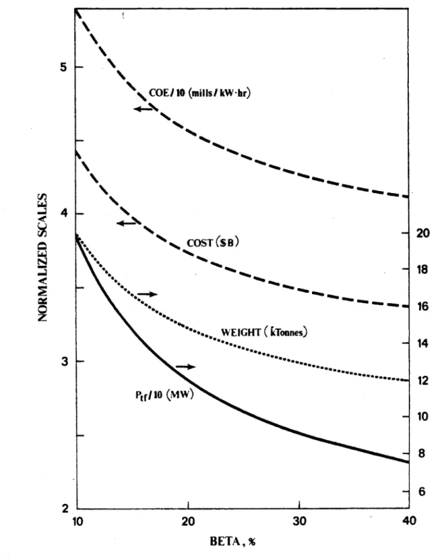
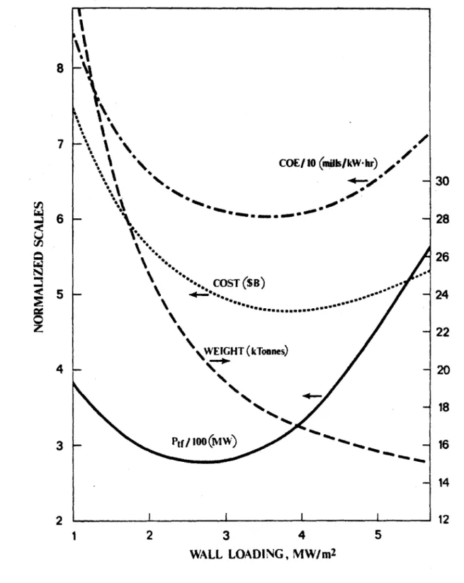
The results of a wall loading scan for an aspect ratio of 5, net electric output of 1200 MWe, elongation of 1.8 and beta of 24% is shown graphically in Figure 2.3. Major radius and nuclear island weight decrease rapidly with increasing wall load between 1 and 3 MW/rn2 and more gradually thereafter due to decreasing wall
22
- 21
20
- COE /10 (milIkW-hr) g18
4'
\ -s 1716
6-
15
COST (S B) "f -of '0 wo * 14 * -1-3
B 13 WEIGHT(kTonnes) - 12 Ptf/lo(M~W) 102
1
1
2
3
4
5
6
7
WALL LOADING, MW/m
2Figure 2.3: Second Stability Wall Load Scan, 1200 MW,, 3 = 24%, k = 1.8, A
area requirements for constant power. Magnetic field on axis increases gradually with increasing wall loading because comparable fusion power is required in a device which is growing smaller.
Recirculating power requirements decrease rapidly up to - 3 MW/m2; after which the curves show a minimum. The volume of the TF coil decreases rapidly at first, accounting for the decrease in recirculating power but then the increasing magnetic field takes effect. Eventually, the device becomes small enough that there is insufficient space inboard in the TF coil to keep the current density in the coil low. Both capital cost and cost of electricity track the size and weight of the devices downward. The curves become flat at high wall loads and exhibit a minimum in the case shown. The costs begin to increase eventually due to the increased recirculating power and the increased operating costs from shorter component lifetimes. The COE curve increases more rapidly after the minimum than the capital cost because a mild degradation of availability with increased wall loading has been included in this case. Without the availability degradation, the COE curve would more closely match the capital cost. The recirculating power and cost increases could be moderated to some degree by relaxing the aspect ratio constraint, for example. However, the basic trends of the curves remain unchanged for a wide range of parameter space.
Preferred wall load is in the area of 4 MW/m2. Most of the benefit for oper-ating at higher wall load (lower size, cost, etc.) is achieved by 4 MW/m2 while going to even higher wall loading will result in shorter component lifetimes and probably lower reliability and more difficult maintenance (and possibly higher cost). For the latter reasons, it may be attractive to go to lower wall loading (< 4 MW/M2). However, significant penalties are paid in terms of size, recirculating power and cost for wall loadings less than - 3 MW/m2.
Net Electric Output
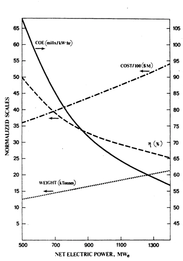
A parametric scan for net electric power outputs between 400 and 1400 MW,
is shown in figure 2.4. The case shown is for a wall loading of 3 MW/m 2, an aspect ratio of 5, and an elongation of 1.8.
Major radius and weight increase almost linearly with increasing net electric power. Plasma current increases moderately as the minor radius increases with larger machine sizes. Since magnetic field remains fairly constant due to its
l-
32
6-30
COE1IO (mills/kWbr)28
-'4
-26
5
0- 624
S*-
22
20
4
-16
14
COST($B)
/
-12
10
82
400
600
800
1000
1200
NET ELECTRIC POWER, MWe
Figure 2.4: Second Stability Net Power Scan, 3 MW/m 2, A = 5, k
= 1.8,