HAL Id: hal-01305749
https://hal.archives-ouvertes.fr/hal-01305749
Submitted on 21 Apr 2016
HAL is a multi-disciplinary open access
archive for the deposit and dissemination of
sci-entific research documents, whether they are
pub-lished or not. The documents may come from
teaching and research institutions in France or
abroad, or from public or private research centers.
L’archive ouverte pluridisciplinaire HAL, est
destinée au dépôt et à la diffusion de documents
scientifiques de niveau recherche, publiés ou non,
émanant des établissements d’enseignement et de
recherche français ou étrangers, des laboratoires
publics ou privés.
A Global Navigation Management Architecture Applied
to Autonomous Robots in Urban Environments
Ide-Flore Kenmogne, Danilo Alves de Lima, Alessandro Corrêa Victorino
To cite this version:
Ide-Flore Kenmogne, Danilo Alves de Lima, Alessandro Corrêa Victorino. A Global Navigation
Man-agement Architecture Applied to Autonomous Robots in Urban Environments. 18th IEEE
Interna-tional Conference on Intelligent Transportation Systems (ITSC 2015), Sep 2015, Las Palmas de Gran
Canaria, Spain. pp.2109-2114, �10.1109/ITSC.2015.341�. �hal-01305749�
A Global Navigation Management Architecture applied to Autonomous
Robots in Urban Environments
Ide-Flore Kenmogne, Danilo Alves de Lima and Alessandro Corrˆea Victorino
Abstract— This paper presents a global behavioral
architec-ture used as a coordinator for the global navigation of an autonomous vehicle in an urban context including traffic laws and other features. As an extension to our previous work, the approach presented here focuses on how this manager uses perceived information (from low cost cameras and laser scan-ners) combined with digital road-map data to take decisions. This decision consists in retrieving the car’s state regarding the global navigation goal, selecting which local navigation task should be executed (either lane following or intersection maneuvers), providing some round constraints and further defining the reference trajectory to be met by the selected local task. This system was experimented in a real autonomous car and provided satisfactory results.
Index Terms— Sensor-based navigation, Global navigation
management, Digital maps.
I. INTRODUCTION
In these last two decades, we have witnessed great ad-vances in autonomous vehicles conception which resulted in a large number of work. The navigation of these vehicles consists in starting from an initial point (qinit) to a final
destination (qgoal) autonomously. Lacroix et al.[1] separated
this mission in three mandatory steps: the perception and localization, the path planning and the decision processes; which is the triptych of the overall navigation task.
The path planning consists in determining which path to take all-through the environments in order to reach the goal. This step is fundamental in view of the static map structure, the robot dimensions and movement constraints, defined in the car’s configuration space [2]. Considering the robot’s environment as geometric (composed of interconnected segments and shapes [3]), several solutions have recently been proposed in the literature. Most of these are waypoints-based approaches, which have shown to be less computational and to provide an entire path (mostly but not always optimal) that must be performed by the robot at each step (see [4], [5], [6] for more details). The implementation of these techniques was stimulated earlier in 2005 by the DARPA Grand Challenge participants, who applied them on off-road autonomous vehicles [7].
Along with the planning, a precise localization must be guaranteed while following the planned path. This constraint implies the use of closed-to-market sensors which are unfeasible for commercial vehicles.
The authors are in Heudiasyc UMR CNRS 7253 Lab-oratory, Universit´e de Technologie de Compi`egne. Contact authors ide-flore.kenmogne-fokam@etu.utc.fr, danilo.alves-de-lima@hds.utc.fr
In this work, we aim to warrant the global autonomous navigation of a vehicle in an urban environment. Contrary to the wide number of solutions seen, while using low-cost sensors, we will propose a behavioral architecture that will render the execution of local navigation tasks more independent from each other and therefore enable the system to react to external events. In this context, the information on Critical Points (CPs) is very useful to efficiently recover the road geometry (used to find the image reference that is to be followed by the local trajectory tracking component). The digital road map information is also important for the whole navigation task.
In the remainder of this paper, we provide in section II an overview of some proposed solutions and the sensors used to achieve the navigation objectives. Section III presents how the route planning has been done. The Global Manager’s architecture is outlined in Figure 3 and detailed in section IV, where some of its advantages and possible applications are mentioned. Before concluding, we summarize our experi-mental results carried out in section V.
II. RELATEDWORKS
Several contests such as the DARPA (Defense Advanced Research Projects Agency) Challenges in the USA (2004, 2005 and 2007); the Korean Autonomous Vehicle Compe-titions (AVC) in Korea (2010, 2012 and 2013), the Grand Cooperative Driving Challenge in Europe 2011 (GCDC) and many others have been organized worldwide to favor the development of autonomous intelligent vehicles. Consider-able issues lie behind the design of these vehicles; starting from the problems related to the localization, the perception of the environment, to the establishment of a reference to be followed by the vehicle. Hereinafter, we underpin approaches implemented by the best participants in these competitions. We would like to emphasize that these solutions ensure a comprehensive autonomous navigation task; however, they do not focus on the more that rest behind the formalization of an overall navigation task management component. This choice was made thanks to our approach stems from a fusion of some of the benefits presented by each of those solutions differentiating mainly on the employed sensors.
Urmson et al. [8] (winner of the DARPA Urban Chal-lenge competition) primarily proposed a behavioral subsys-tem composed of several sub-components such as a “Goal
selection”, a “Drive down road” and an “intersection han-dling”. The “Goal selection” is responsible for estimating
by a global route planner (RNDF) and further generating the local goal for execution by the motion planner. The “Drive
down road”, for its part uses the surrounding conditions of
the vehicle (provided by visual sensors and the tight coupled laser scanner and radar) to find which road lane should be followed and what distance interval must be maintained between cars. Finally, the “intersection handler” uses data from the pan-head sensors to compute a save set of steering velocities that can be executed by the motion planner while avoiding collision with surrounding vehicles (output speed, acceleration and lane to be tracked). Although the aim has been reached, this is not marketable because it used accurate albeit expensive sensors such as : an inertial tightly coupled GPS bridges and outages (aided with a sub-meter accuracy), a high-dynamic-range camera (PGF) and many others. Miller et al. [9] also proposed a similar solution but did not really focused on the benefits of this component as Urmson et al. did.
Unlike Urmson et al., Bacha et al. [10] (third place in the race) who proposed a more structured behavioral management, used a hybrid deliberative/reactive architecture to analyze, select the appropriate behavior to adopt, and define a safe path. Their strength relies on the ability of this planner to take the right decision. Actually, the system is currently divided into several drivers associated with differ-ent types of situations. So, Taking the right decision consists in choosing the right driver to be applied at a specific time and the behavioral Integrator is responsible for this action. It thereafter outputs the corresponding velocities, accelerations and other parameter limits according to the selected behavior. Meanwhile, the sensors used here are not too different from the ones used before. Despite the difference between these two methods, they are both aimed to locally plan paths between the checkpoints (defining waypoints to guide the robot navigation) and correct the robot’s lateral position by means of a high precision localization system and the RNDF information.
Ziegler et al. [11], participant of the GCDC, lately com-pleted the autonomous guidance in urban environments using a preregistered reference path for the vehicle. A Differential GPS-aided inertial navigation system was used during the tracing process, giving more environment information to the digital map (such as lanes numbers, speed limits, stop signs, etc.) in a post-management step. This post-management was carried-out in a user-generated street map interface, called OpenStreetMap (OSM). Consequently, during the experi-ment, point feature and lane marking based localization was performed with less costly sensors. However, concerning the decision making process, a Behavior Generation component modeled using state chart notation was used. Therefore, a state will be activated if a series of rules are valid at the same time (leading either to Corridor Driving -while avoid-ing static obstacles - or Yieldavoid-ing&Mergavoid-ing-for intersection crossing).
Despite the fact that these methods were able to guide the robot globally, they were strongly dependent on the localiza-tion system’s accuracy (in local tasks) . Victorino et al. [12]
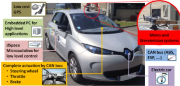
Fig. 1. Fully actuated electric car APPACHE with some available resources.
proposed a new approach for indoor environments with a topological representation of the robot path. In this case, nodes were linked by corridors characterizing the relations of accessibility (between doors and crossing corridors). When in a corridor, the robot can move only to the next node, by using a sensor-based control strategy with no localization requirements for example. But, if the robot is near a node, it must localize itself with relation to this node and therefore take the appropriate direction (next in the topology).
If we extend the topology in [12] to urban environments, the corridors are the roads, without any other way to go, and the nodes are the points where some action must be taken (intersections or traffic light stops). In our previous work [13], the nodes were called by critical points (CPs), where, in comparison to the waypoints, they are sparsely defined and do not represent the shape of the path. Thus, while following the road, robot localization is not required (due to the absence of waypoints), and some sensor-based approach is enough to guide the vehicle to the next CP. At the CP, the vehicle localization can be performed by low cost systems, which can be less dependent on GPS sensors.
This navigation principle mimics the use of a simple personal vehicular GPS which guides the human driver to the desired destination by giving instructions only on some specific points. A topological segmentation was also applied, helping to define a high-level abstract world model which supports the decision-making process of an autonomous car. We will then use this model to define a Global Navigation
Manager (decision maker) which is able to achieve the same
goal as the previous solutions proposed in the literature but using less redundant information and also less costly sensors. In addition to its main goal in the Global Navigation process, this architecture could eventually be applied with different class of robots and further be suited for convoy missions. Moreover, here we validated this entire approach in a real autonomous car.
III. GLOBALROUTEPLANNING
The Global Route Planner developed in this work is similar to the one presented by Pereira et al. in [13]; where the roads are represented by corridors and their intersections by critical points (CPs). Based on digital maps (provided by the OSM), a routing table was generated after a path planning by structuring the global navigation from qinit to
TABLE I
ROUTING TABLE FOR THE PATH REPRESENTED IN THEFIGURE2.
CP description CP geometry
Node Lat Lon Vmax Rlanes Rway Ra Nroads Θ1 D1 Θ2 D2
qinit 49.392 2.798 30 1 1 0 1 180 4 -
-1 49.400 2.800 50 2 2 0 2 110 4 290 1
..
. ... ... ... ... ... ... ... ... ... ... ...
Fig. 2. Example of a road intersection illustrating the routing table definitions, where the yellow arrows indicates the traffic way.
have been divided in two parts, where the first is related to the road (way) description after the CP, and the second represents the CP geometry with the angle and direction of every intersecting road. The first part has a constant size, once the possible road parameters are always the same, and the second one has the size depending on the number of roads intersecting the CP. The columns description are as follow:
• Node: with the path’s CPs ordered from qinit to qgoal; • Lat and Long: the latitude and longitude coordinates
of the CP in degrees;
• Vmax: the maximum speed limit of the road (in km/h); • Rlanes: the number of available lanes in the road (even
if it is a two way road);
• Rway: the road classification in one way (1) or not (2); • Ra: the CP definition as roundabout point or not; • Nroads: the number of roads at the CP;
• Θ1..Nroads and D1..Nroads: the sets of angle and
direc-tion for each road at the CP, ordered counterclockwise. Θ1..Nroads are the formed angles between the current
road and the next one in the intersection. D1..Nroads
indicate if the road is the path to follow(4), a wrong way (arrival) road (3), a right way (departure) road(2), an arrival/departure road(1), or if it is the goal point(0). Table I presents an example of routing table for the condition shown in the Figure I. A complete routing table based on the OSM data will be presented in the experimental results of this work (Section V). The global navigation, based on the routing table, is performed by following the directions indicated as path to follow (4) at each CP. The management of this table during a sensor-based navigation is presented next.
IV. GLOBALNAVIGATION MANAGEMENT
One cornerstone of the navigation task is the decision making process. Therefore, this paper presents a formalized sensor-based navigation management system aiming to deal
Fig. 3. Autonomous Navigation Global architecture including a Navigation Management component (BehavioralComponent).
with the global navigation problem in an urban environ-ment. Considering the autonomous navigation architecture presented in Figure 3, we propose a navigation management responsible of executing the global route generated by the mission-planner (based on the digital map provided by OSM and low cost sensors). This subsystem would be able to perform lane changes, handle transitions between local tasks and even provide information about the vehicle state (x, y, θ) and the surrounding road to a nearby infrastructure or vehicle if necessary.
The global architecture in Figure 3 puts an emphasis on the location of our behavioral component in the global navigation context. This figure also indicates different links and data exchanges between this component and other navigation subsystems. In this section, we present how the navigation state is defined (possible states and their representation). Then, we highlight the methodology (algorithm) employed to determine this state at a given time. And finally, we present the way transitions are being conducted in other to derive the local task reference trajectory that will be tracked by the control component.
Navigation State Transitions
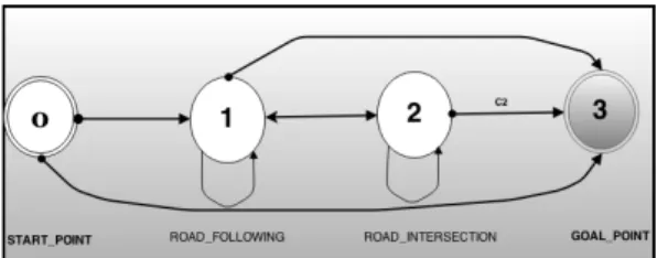
While structuring the navigation manager, we were led to analyze and consider the Global Navigation problem as successive states in which the vehicle could be all along the process of its mission. Figure 4 depicts these different states and the connections between them illustrate the possibility to go from one state to another.
Fig. 4. Global navigation state transitions.
START POINT (state0): represents the vehicle at the initial position qinit which is the first CP in the Routing
Table. To reach the next CP, the vehicle should pass through a corridor. This will imply the navigation task to switch to the State1 (if, of course qinit̸= qgoal).
ROAD FOLLOWING (state1): represents the vehicle is computing a road lane following. This means the vehicle is between two critical points. As soon as it approaches one of these critical points, the navigation manager detects this intersection and immediately change the navigation state to
State2. It could also stop all the process in case this detected
CP is the qgoal.
ROAD INTERSECTION (state2): for the vehicle in making a road intersection maneuver. This state is maintained throughout the intersection traversal and it either switches back to State1 or it has reached the final destination and therefore changes the state to GOAL POINT(state3).
Determining the navigation state at a defined instant
Algorithm 1 describes how the navigation state is be-ing retrieved and updated at each time by the navigation management. It gives details on the conditions of transition from a state to another. First of all, if the robot is at the initial position (meaning that State = START POINT), we find the next critical point to be reached in the RT and automatically change the state to ROAD FOLLOWING. Then, if the state was already on road lane following, the
State selector computes both the distance to the critical point dist (Compute distance2CP) and the angle difference δθ
(compute angle diff) between the actual car direction and the desired CP’s direction. If this distance is lower than the previous distance, lower or equal to a defined threshold
dmax and δθ lower than an angle tolerance (function of
street corner angle recovered using the local occupancy grid); then the intersection crossing is activated (State = ROAD INTERSECTION). This whole conditions have been tested by the function Verifydistance2Intersection and is tested true if bool = 1. Otherwise, the state remains the same or passes to GOAL POINT if the next CP is the goal. The possibility to switch from ROAD INTERSECTION to ROAD FOLLOWING is presented when the distance to the actual CP is increasing while the δθ decreases until it
reaches an intersection-living distance threshold smaller than
dmax; this marks the end of the traversal. This is verified
by the function Verifydistance2Intersection, which outputs
bool = 1 (intersection traversal ended, the state move back to
ROAD FOLLOWING). Finally, the State = GOAL POINT is reached whenever the vehicle is very close to the last critical point.
Algorithm 1 Retrieve the Global Navigation Task state. Get Navigation State(x, y, θ, CP, dmax)
1: dist = Compute distance2CP(x, y) 2: δθ= compute angle diff(θ, θCP)
3: if (CP == qinitandState == ST ART P OIN T )
then
4: find the next Critical point CP
5: compute car distance to the critical point dist 6: change State = ROADF OLLOW IN G 7: end if
8: if (State == ROADF OLLOW IN G) then 9: bool = Verifydistance2Intersection(dist,δθ)
10: if (bool == 1) then
11: State = ROADIN T ERSECT ION 12: else
13: If CP == qgoal
14: State = GOALP OIN T 15: end if
16: end if
17: if (State == ROADIN T ERSECT ION ) then 18: bool = VerifyIntersectionLiving(dist,δθ)
19: if (bool == 1) then
20: State = ROADF OLLOW IN G 21: find the next Critical point CP 22: end if
23: end if
24: if (State = GOALP OIN T ) then
25: End task, Goal have been reached : speed = 0 26: end if
27: return State
The proposed algorithm is very generic, simple and can therefore be adapted to more complex situations.
Global manager’s procedure
After having determined at what level the vehicle is, the global behavioral component computes, according to the founded state, the motion that must be performed by the local task. We have distinguish two main states :
• State 1 : Road Lane following
In case the vehicle is between two critical points, we used the methodology presented by Lima et al. [14]; where the navigation reference is represented in the sensor frame. It consist on using the perceived information from the camera to define a visual objective (Visual Servoing Control) that must be reached. The local controller will then be able to regulate the actual lateral error based on this input. The approach is known not reactive. Meanwhile, the authors proposed another methodology called Image-based Dynamic Window Approach (IDWA) to avoid obstacles present in the local occupancy grid; but the final approach
Fig. 5. Global navigation experiment for the routing table defined on Table II.
that has been adopted is a hybrid controller named as VS+IDWA, using the benefits of both control design.
• State 2 : Road intersection maneuver (traversal) The behavioral manager, in case of an intersection, categorizes two main situations. The case the CP is a roundabout or a normal intersection (either left turn or right turn). It constructs a reference based on the principle presented by Jochem in [15]. This consist on reconstructing the intersection’s instantaneous rotation center to compute the curvature that the car most follow (arc shape formed by the tangents between the actual CP and the car directions). Once the turning radius is computed, the management express it in the sensor frame (approximate the curve by a polygonal shape) and then activate the image-based hybrid controller VS+IDWA.
V. EXPERIMENTALRESULTS
To validate the proposed global navigation management, we have implemented and integrated it on the experimen-tal car APPACHE (see Figure 1), using its resources for environment perception and local navigation control. This vehicle is an important test bed for our navigation approach, but, due to the current modifications, it is still not allowed to run in the city roads. However, at the Innovation Center of the Universit´e de Technologie de Compi`egne there exist a circuit called SEVILLE; used for autonomous navigation experiments. This circuit possesses some challenging sce-narios such as: tight road intersections, roundabouts, sharp turns, and up&downhills (≈ 3.5◦), which was used during the validation of our methodology.
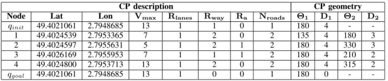
Table II presents the routing table used for our experiment using only the OSM data. The entire system was running at 10 Hz, while the experimentation was carried out in order to present the global navigation management capabilities during the road following and the road intersection maneuvers in full autonomous mode. As SEVILLE is a closed circuit, the path planning was not applied, it only required of the CPs where the vehicle must pass. The localization tolerance for each CP
Fig. 6. Some screenshots of the environment perception system illustrate the management during the road following and intersection maneuvers tasks.
was set to 10 m, regarding the GPS and OSM errors. Figure 5 shows the global navigation movement performed by the APPACHE for each CP in the Global Routing Table II. In this figure, we could predict the state transitions diagram through which our navigation task have been during each step of the process (states given by the management system). This state transition have been validated by the results obtained in Figure 6. So, not only did our system achieve the goal, but at each level of the task, it could perfectly identify intersections and provide a reference trajectory to be followed (yellow line on the screenshorts of Figure 6). In this Figure, the vehicle always follows the yellow line. The Red line means wrong way road and the green line means right way (or feasible way, but not the one to be followed). Each time a road intersection is approached, the Global Management component outputs an image with two lines (in our scenario) representing the way to take and all other ways with different color than yellow according to the feasibility of the direction. Approaching the GOAL POINT, we can see that the line feature outputed delimit the location of the goal by painting in dark all the point of the line situated after this GOAL POINT.
Additionally, the global navigation management could also perform the speed limitation for each local road. Figure 6 shows the linear velocities applied for the complete move-ment with the limitation performed for each routing table row. In this figure, the global management is evidenced during the CP transitions, where the road nominal speed (defined as 5, 7, and 13 km/h) is limited to 5 km/h; this to allow safe intersection maneuvers. Also, in order to mimic a
TABLE II
ROUTING TABLE FOR THE GLOBAL NAVIGATION MANAGEMENT EXPERIMENTS.
CP description CP geometry
Node Lat Lon Vmax Rlanes Rway Ra Nroads Θ1 D1 Θ2 D2
qinit 49.4021061 2.7948685 13 1 1 0 1 180 4 - -1 49.4024539 2.7953365 7 1 2 0 2 135 4 180 3 2 49.4024597 2.7955631 5 1 2 1 2 180 4 330 3 3 49.4026169 2.7955953 7 1 1 1 2 180 4 210 2 4 49.4024800 2.7953713 13 1 2 0 2 180 4 315 2 qgoal 49.4021061 2.7948685 13 1 0 0 1 180 0 -
-human driver behavior and prepare the vehicle for the arrival of an intersection, we anticipate (dmax) the speed limitation
to 5 m before the CPs. This distance allows a smooth arrival in the intersection for the current speed limitations. However, for high speed applications, this distance must be related to the vehicle maximum deceleration for a smooth speed reduction.
VI. CONCLUSION ANDFUTUREWORK
This paper proposed a new formalized sensor based nav-igation management system aiming to deal with the global navigation problem of an autonomous vehicle in an urban environment. We focused on the structure of the behavioral architecture, mainly on the way decision making is being handled to ensure a more robust transition and reference processing between the lane following and the intersection maneuvering. Our final system was integrated in the AP-PACHE, an experimental car equipped with low cost sensors. Although the information available was very imprecise , the system successfully accomplished its mission by providing instantaneous feedback of its state and also retrieving the appropriate reference trajectory corresponding to each cur-rent local task between two CPs. The results showed the good performances of the proposed solution which was also able to provide free-to-go trajectory in case of an obstacle detection. Despite the system’s efficiency, the problem of discontinuity of the image reference at intersection traversal still needed a deeper consideration. In this context, the methodology for intersection traversal shortly introduced in Section IV will be developed in future works. In addition, more road constraints must be considered, like road lanes, stop signs, the road priority, etc., to allow road following and intersection maneuvers closer to real situations.
ACKNOWLEDGEMENT
This work was partly carried out in the framework of the Equipex ROBOTEX (Reference ANR-10-EQPX-44-01) and funded in the framework of the Labex MS2T (Reference ANR-11-IDEX-0004- 02).
REFERENCES
[1] S. Lacroix, R. Chatila, S. Fleury, M. Herrb, and T. Simeon, “Au-tonomous navigation in outdoor environment: adaptive approach and experiment,” Proceedings of the 1994 IEEE International Conference
on Robotics and Automation, vol. 1, pp. 426–432, 1994.
[2] H. Choset, L. Kevin M, H. Seth, K. George A, T. Sebastian, and B. Wolfram, Principles of Robot Motion: Theory, Algorithms, and
Implementations. Cambridge, MA: MIT Press, 2005.
[3] M. Sotelo, F. Rodriguez, and L. Magdalena, “Vision-based navigation system for autonomous urban transport vehicles in outdoor environ-ments,” Intelligent Vehicle Symposium, 2002. IEEE, vol. 1, pp. 52–57, 2002.
[4] M. T. S. Ibrahim, S. V. Ragavan, and S. G. Ponnambalam, “Way point based deliberative path planner for navigation,” in IEEE/ASME
International Conference on Advanced Intelligent Mechatronics, AIM,
2009, pp. 881–886.
[5] W. Guo, Z. Zhu, and Y. Hou, “Graphical model-based recursive motion prediction planning algorithm in stochastic dynamic environment,”
Control and Decision Conference (CCDC), 2010 Chinese, pp. 3473–
3478, 2010.
[6] L. C. Fernandes, J. R. Souza, G. Pessin, P. Y. Shinzato, D. Sales, C. Mendes, M. Prado, R. Klaser, A. C. Magalh˜aes, A. Hata, D. Pigatto, K. Castelo Branco, V. Grassi, F. S. Osorio, and D. F. Wolf, “CaRINA Intelligent Robotic Car: Architectural design and applications,”
Jour-nal of Systems Architecture, vol. 60, no. 4, pp. 372–392, 2014.
[7] S. Thurn, M. Montemerlo, H. Dahlkamp, and D. Stavens, “Stanley : The Robot that Won the DARPA Grand Challenge,” Journal of Field
Robotics, vol. 9, pp. 661–692, 2006.
[8] C. Urmson, J. Anhalt, D. Bagnell, C. Baker, M. N. Clark, J. Dolan, and D. Duggins, “Autonomous Driving in Urban Environments: Boss and the Urban Challenge,” Journal of Field Robotics, vol. 8, pp. 425–466, 2008.
[9] I. Miller, M. Campell, D. Huttenlocher, F.-R. Kline, and A. Nathan, “Team Cornells Skynet: Robust Perception and Planning in an Urban Environment,” Journal of Field Robotics, vol. 8, pp. 493–527, 2008. [10] A. Bacha, C. Bauman, R. Faruque, M. Fleming, C. Terwelp, and
C. Reinholtz, “Odin: Team VictorTangos Entry in the DARPA Urban Challenge,” Journal of Field Robotics, vol. 8, pp. 467–492, 2008. [11] J. Ziegler, T. Dang, U. Franke, H. Lategahn, P. Bender, M. Schreiber,
T. Strauss, N. Appenrodt, C. G. Keller, E. Kaus, C. Stiller, and R. G. Herrtwich, “Making Bertha Drive An Autonomous Journey on a Historic Route,” Intelligent Transportation Systems Magazine,IEEE, vol. 6, no. 2, pp. 8–20, 2014.
[12] A. C. Victorino, P. Rives, and J.-J. Borrelly, “Safe Navigation for Indoor Mobile Robots. Part II: Exploration, Self-Localization and Map Building,” pp. 1019–1039, 2003.
[13] E. C. M. Pereira, D. A. Lima, and A. C. Victorino, “Autonomous vehicle global navigation approach associating sensor based control and digital maps,” in Robotics and Biomimetics, 2014. ROBIO 14,
IEEE International Conference, 2014.
[14] D. A. Lima and A. Victorino, “An image based dynamic window approach for local navigation of an autonomous vehicle in urban environments,” 2014, p. 6.
[15] T. Jochem, D. Pomerleau, and C. Thorpe, “Vision-based neural net-work road and intersection detection and traversal,” Proceedings 1995
IEEE/RSJ International Conference on Intelligent Robots and Systems. Human Robot Interaction and Cooperative Robots, vol. 3, pp. 344–