HAL Id: insu-00311167
https://hal-insu.archives-ouvertes.fr/insu-00311167
Submitted on 13 Aug 2008HAL is a multi-disciplinary open access archive for the deposit and dissemination of sci-entific research documents, whether they are pub-lished or not. The documents may come from teaching and research institutions in France or abroad, or from public or private research centers.
L’archive ouverte pluridisciplinaire HAL, est destinée au dépôt et à la diffusion de documents scientifiques de niveau recherche, publiés ou non, émanant des établissements d’enseignement et de recherche français ou étrangers, des laboratoires publics ou privés.
Conditions for the growth of a long-lived shallow crustal
magma chamber below Mount Pelee volcano
(Martinique, Lesser Antilles Arc)
Catherine Annen, Michel Pichavant, Olivier Bachmann, Alain Burgisser
To cite this version:
Catherine Annen, Michel Pichavant, Olivier Bachmann, Alain Burgisser. Conditions for the growth of a long-lived shallow crustal magma chamber below Mount Pelee volcano (Martinique, Lesser Antilles Arc). Journal of Geophysical Research, American Geophysical Union, 2008, 113 (B07209), pp.1-16. �10.1029/2007JB005049�. �insu-00311167�
Conditions for the growth of a long-lived shallow crustal magma
chamber below Mount Pelee volcano (Martinique, Lesser Antilles
Arc)
Catherine Annen : Section des Sciences de la Terre, Université de Genève, Genève, Switzerland
Michel Pichavant : Institut des Sciences de la Terre d'Orléans, UMR6113, Université d'Orléans, CNRS, Orléans, France
Olivier Bachmann : Section des Sciences de la Terre, Université de Genève, Genève, Switzerland
Now at Department of Earth and Space Sciences, University of Washington, Seattle, Washington, USA
Alain Burgisser : Institut des Sciences de la Terre d'Orléans, UMR6113, Université d'Orléans, CNRS, Orléans, France
Abstract
The compositional homogeneity of silicic andesites emitted during the 13,500-year-long last eruptive cycle of Mount Pelee suggests that the physical state of the magma chamber was largely unmodified during this period. Experimental phase equilibria on Mount Pelee recent products indicate that pre-eruptive magma temperatures and pressures were in the range of 875–900°C and 2 ± 0.5 kbar, respectively. The estimated average eruption rate was 7.5 × 10⁻⁴ km3/a with an average volume of about 0.3 km3 per eruption. An analytical model for a spherical magma chamber indicates that a magma flux of 4–5 × 10⁻⁴ km3/a can maintain a magma chamber of 0.3 km3 above 875°C below Mount Pelee. However, observations of plutons suggest that magma chambers may grow by addition of sheet-like intrusions. With numerical simulation we show that a minimum sheet accretion rate of a few centimeters per year is required to grow a persistently active magma chamber independently of the intruded volumetric flux. This minimum injection rate is higher if the heat transfer is enhanced by convection processes. The limited ability of an arc crust to extend and accommodate dikes suggests that magma injections are sills or, if they are dikes, that most of the volume injected in the magma chamber is eventually erupted. In a conductively cooling igneous body formed by sills injected at a rate of a few centimeters per year, most of the injected magma
completely solidifies and only a small part of the body (about 10–20%) is above 875°C and able to feed eruptions.
Keywords: Mount Pelee, heat transfer, magma chamber, injection rate, magma chamber
1. Introduction
The rate of magma input in crustal arc magma chambers and the proportion of this magma that is erupted are still largely unknown. The ratio of eruptive to intrusive rocks in arcs as estimated by White et al. [2006] varies over a very wide range from 1:1 to more than 1:30, with an average of 1:5. The mass and heat balance in the magma chamber controls the geochemical and petrological evolution of the magma. The lifetime of a closed magma chamber of small volume and andesitic composition is no more than a few thousand years [Blake and Rogers, 2005; Hawkesworth et al., 2000]. To remain at high temperature, a magma chamber needs to be replenished regularly so that the heat advected by new magmas balances the heat loss by diffusion through wall rocks and by eruptions. Part of this magma might crystallize and never erupt, forming a subvolcanic cogenetic pluton.
[3] The shapes and dimensions of arc magma chambers are poorly constrained [Lees, 2007]. Field and geophysical studies of granite plutons that might represent fossil magma chambers indicate that they are typically tabular with low aspect ratios [Cruden, 1998; Cruden and McCaffrey, 2001; Miller and Miller, 2002; Petford et al., 2000], though small volume arc magma chambers may be more dike-like [La Delfa et al., 2001; Martin-Del Pozzo et al., 2008;
Pichavant et al., 2002]. While the growth rate of granite bodies is still controversial [Coleman et al., 2004; de Saint-Blanquat et al., 2006; Glazner et al., 2004; Petford et al., 2000], it is now accepted that they are constructed by agglomeration of discrete sheets [Annen et al., 2006b;
Coleman et al., 2004; Cruden and McCaffrey, 2001; de Saint-Blanquat et al., 2001; de Saint-Blanquat et al., 2006; Glazner et al., 2004].
For Mount Pelee, insights on the depth and temperature of magma crystallization are provided by experimental petrology and phase equilibria. In the study presented here, data provided by experimental petrology are used to constrain the modeling of the repeated replenishment of Mount Pelee magma chamber. The following issues are addressed: (1) what are the magma fluxes needed to maintain a magma chamber at temperatures above 875°C over more than 13,500 years? (2) what are the dimensions and shapes of the successive magma additions that build up the magma chamber?
2. Geological Background
Mount Pelee volcano is located on the Northern part of the island of Martinique in the Lesser Antilles Arc. Three cycles of activity have been identified. The ages of the first cycle that built up the primitive Pelee [Vincent et al., 1989] are poorly known [Pichavant et al., 2002]. It is younger than neighboring Mount Conil that has been dated at 0.6 Ma [Nagle et al., 1976] and a breccia belonging to Mount Pelee first cycle has been dated at 0.4 Ma [Bellon et al., 1974]. The second cycle lasted from 40,000 to ~19,500 years BP and is characterized by the emission of predominantly basaltic andesites. After a gap in the activity of 6000 years, the current cycle started ~13,500 years ago and erupted plinian and pelean products of mostly silicic andesite composition [Fichaut et al., 1989]. Fichaut et al. [1989] identified 34 eruptions for this cycle and estimated the volume per eruption at 0.1–0.5 km3. This last 13,500 years long cycle is characterized by a remarkable homogeneity in the composition of emitted products, which suggests that the physical state of the magma chamber did not vary appreciably before each eruption. The andesites are porphyritic with 35–58 vol% crystals [Pichavant et al., 2002]. Magma pre-eruptive temperatures and pressures have been
experimentally determined and were found to be constant for three recent eruptions (P1, 650 years B.P., 1902, 1929) to 875–900°C and 2 ± 0.5 kbar, respectively [Pichavant et al., 2002].
The erupted andesites do not show clear mineralogical evidence for marked reheating events [Martel et al., 1998; Pichavant et al., 2002], and this suggests that the erupted magma did not significantly cool below 875°C. Existence of an 8 km deep magma chamber staying in a quasi-steady state during the last 13,500 years implies that this chamber is regularly recharged by magma from depth.
[6] In the present paper, we use an analytical solution and a series of numerical simulations to explore the conditions in terms of magma chamber geometry and magma fluxes that are required to maintain a volume of 0.3 km3 of magma above 875°C at pressures of 2 ± 0.5 kbar over 13,500 years.
3. Spherical Magma Chamber: Analytical Approach to Magma
Flux Estimate
To calculate minimum replenishment rates in the magma chamber that are needed to keep the magma above a critical temperature Tcr, we first use a simple analytical model. We consider a
spherical magma chamber of radius R in an infinite medium of far-field temperature T∞ and
replenished by a hot magma at Tinj. Volume flux of magma in the chamber, qin, has to be such
that the surface of the sphere remains at the critical temperature Tcr. We consider that the
magma crystallizes from Tinj down to Tcr, whereas it cools down conductively like country
rock below Tcr. Thus, the thermal flux brought by the injected magma, Qin (W), is equal to the
temperature difference between injected and resident magmas plus the latent heat released by crystallization:
where ρ is magma density (2500 kg/m3), cp is magma heat capacity (1000 J/kg K), f is crystal
fraction at Tcr = 875°C (54 wt%), and L is latent heat (3 × 10⁵ J/kg) [Bohrson and Spera, 2001; Holbrook et al., 1992; Robertson, 1988]. We assume that this thermal energy is dissipated from the center of the sphere so that, by symmetry, it is sufficient to follow the temporal evolution of temperature as a function of distance from the sphere center. The magma either accumulates in the chamber or is erupted after cooling to Tcr. We only
considered the case in which no magma accumulates, as there is no analytical solution for the thermal evolution of a sphere growing in an initially cold medium. The intrusions can then be viewed as occurring at a point source from which heat is drawn away in an infinite medium initially at T∞. Temperature decay away from the center is given by [e.g., Baehr and Stephan,
2006, p. 189]:
where k is thermal conductivity (W/m K). Assuming that the replenishment rate varies slowly compared to the heat conduction away from the chamber (i.e., intrusions are small compared to chamber size), we can write Qin = −Qout. In other words, the thermal flux Qin brought by
sphere remains at Tcr by setting T(R, t) at Tcr. Thus, by combining (1) and (2), we can easily
express the injection rate qin as a function of time:
We used Tcr = 875°C, R = 415 m (i.e., a chamber volume of 0.3 km3), T∞ = 160°C (8 km
depth at 20°C/km), Tinj = 990°C, k = 2.24 W/m K and found that a magma flux of 40 × 10−4
km3/a for 1000 years decreasing to 5 × 10⁻⁴ km3/a in 15,000 years and then maintained close to this level can isochemically sustain a 0.3 km3 magma chamber. Such magma fluxes are compatible with the eruption rates estimated at Mount Pelee.
4. Magma Chamber Built up by Sheet Accretion: Numerical Approach to
Injection Geometries
Field and geophysical studies of plutons show that most igneous bodies are not spherical but tabular [e.g., Cruden, 1998; Cruden and McCaffrey, 2001; Miller and Miller, 2002; Petford et al., 2000]. The analytical approach does not enable us to address whether the thermal history of the magmatic system could be influenced by the shape of the successive magma additions. Moreover, if only part of the magma injected in the chamber is erupted, the magma body is growing with time. This also cannot be addressed by a simple analytical approach. We used instead numerical simulations of heat transfer in magma chamber and varied the shape of intrusion from sill to dike.
4.1. Method
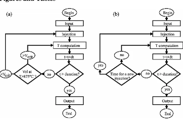
Minimum magma fluxes (in km3/a) and sheet injection rates (in m/a) necessary to maintain the magma chamber above 875°C are estimated with the numerical model illustrated in Figure 1a. The parameters input in the program are the geometry of intrusions as illustrated in Figure 2, their thickness and diameter, the ratio of eruption over intrusion r, the liquidus and solidus temperatures of the magma, and the critical volume of the magma chamber that is not allowed to cool below 875°C. We take a critical volume of 0.3 km3 that corresponds to the average
eruption volume [Fichaut et al., 1989]. The simulation begins with the emplacement of a first intrusion. After each time step, the volume of the magma chamber that is above 875°C is calculated. As soon as this volume is smaller than the critical volume, a new intrusion is emplaced. This process is repeated over 50,000 years and the volumetric fluxes and 1-D injection rates are calculated by dividing the volume, respectively the thickness, of dikes or sills by the time interval between two injections.
Once the minimum injection rate needed to keep the chamber above 875°C is estimated, additional simulations are run with a fixed injection rate and the evolution over time of the volumes of eruptible magma (magma at temperatures above 875°C) is calculated (Figure 1b).
The model is conductive and includes the latent heat generated by crystallization of the magma and by melting of previously emplaced magma or country rock so that:
where X is melt fraction. The thermal conductivity at 0°C k0 is 2.5 W/m K and k varies with
temperature [Clauser and Huenges, 1995]:
4.1.1. Geometry and Discretization
We will refer to the finite body of magma that is added to the magma chamber as an intrusion. The shape of the modeled intrusions is sheet-like and either vertical (dikes; Figures 2a and 2b) or horizontal (sills; Figures 2c and 2d). The sheet intrusions (sills or dikes) are assumed to be wafer-shaped and axisymetric. To express the rate at which the sheets of magma, that can rapidly solidify or stay partially molten, are amalgamated, we will indifferently use the terms of injection rate or accretion rate.
Evolution of temperature is calculated in a half-space with the method of explicit finite differences with a finite volume approach [Holman, 1997; Tannehill et al., 1997]. The system of magma and crust is discretized in two dimensions and represented by a grid of square cells (Figure 2). The calculations are performed in the plane that contains the sheets axis of
symmetry (Figure 2). A temperature and a melt fraction characterize each cell. In the case of sills, the geotherm is oriented as the intrusions axis of symmetry and the whole system is axisymmetric. In this case, the 3-D system reduces to a 2-D system owing to the use of cylindrical coordinates (simulation in quasi-3-D, see Appendix A). In the case of dikes, because the sheets axis of symmetry is perpendicular to the geothermal gradient, the whole system of intrusion and country rocks is not axisymmetric. For dikes, we used Cartesian coordinates because cylindrical coordinates would overestimate temperature above the dike and underestimate them below the dike. However, use of Cartesian coordinates implies that heat loss in third dimension at the tip of dike is neglected, which resulted in an overestimation of minimum injection rates.
The initial condition is temperatures distribution corresponding to a typical arc geotherm of 20°C/km. The top boundary condition is a constant temperature of 20°C at Earth's surface. To ensure that the size of thermal anomaly is smaller than the modeling domain, the bottom and right boundaries of modeling domain are at a distance of the intrusive body floor and wall that is twice the diffusion length ( t)1/2, where is the thermal diffusion and is equal to k/ρcp and t
is the duration of the simulation. The bottom and right boundaries are at a fixed temperature corresponding to the initial geotherm.
As long as the time interval between two magma injections is short in comparison with the total simulation duration, the thermal evolution of the system depends on the average injection rate and not on the exact thickness of the intrusions. To minimize the truncation
error, we did a series of trials with different cell numbers. We found that for our results to converge, the sheets thickness must be equal or more than eight times a cell length. For most simulations the thickness of individual intrusions is fixed to 200 m and the cell dimension to 25 × 25 m. For some simulations where better accuracy is desirable, the intrusion thickness is 80 m and the cell dimensions are 10 × 10 m. Simulation time steps are calculated according to the Fourier number criteria. The maximum injection rate that can be calculated is equal to the intrusion thickness divided by the time step.
The ratio of erupted versus intrusive volumes, i.e., the proportion of the magma that is withdrawn from the magma chamber to feed eruptions, is not known a priori. We have tested the models with several erupted to intruded volume ratios r. One end-member is when all the intruded volume is erupted and r is 1. In this case the volume of the magma chamber is constant and equivalent to the volume of one injection. To simplify, we still use the term magma chamber even though no large magma reservoir builds up. The other end-member is r = 0, in which case the volumes that are erupted are insignificant relative to the volumes intruded. Between these two end-members, we have tested the model with r = 1/2 and r = 1/5, where half and one fifth of the intruded volumes are erupted.
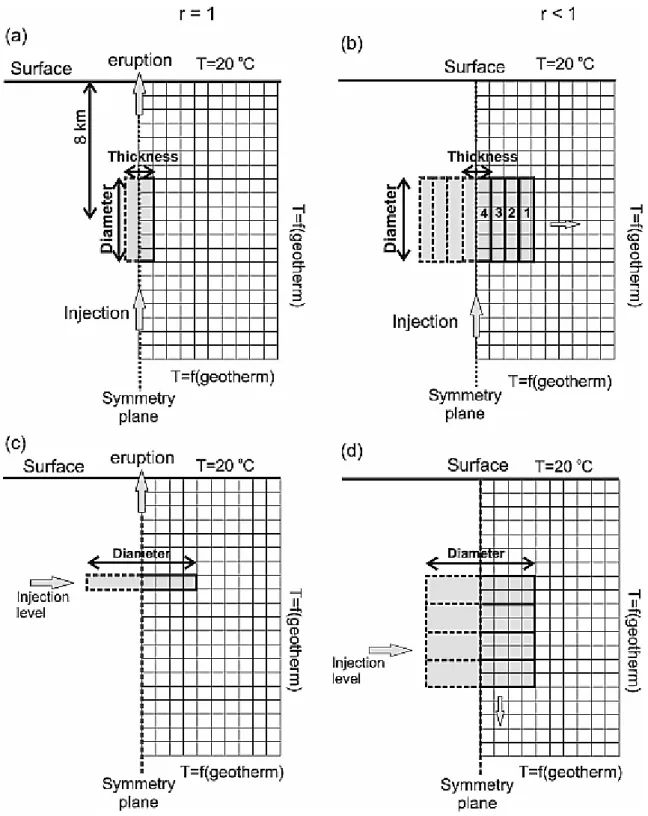
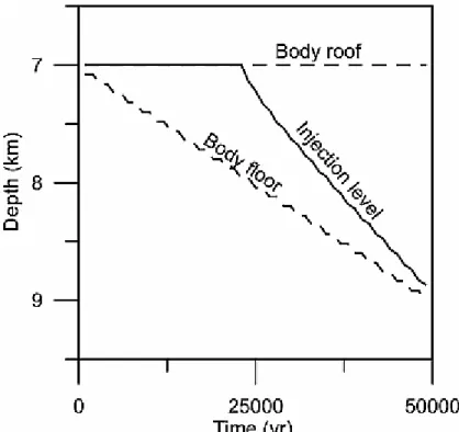
If intrusions are dikes and r is less than 1, each dike intrudes in the center of former one and the new volume is accommodated in the half-domain by moving the cells on the right of the dike wall outward (Figure 2b). Similarly if intrusions are sills and r is less than 1, their volume is accommodated by moving the cells below the sill downward (Figure 2d) assuming intrusion accommodation by magma chamber floor depression and volume exchange with a deeper deflating reservoir [Cruden and McCaffrey, 2001]. Field observations on plutonic bodies indicate that injections of magma spread over the mushy part of the magma chamber [Blundy and Sparks, 1992; Wiebe and Collins, 1998]. To account for this observation, in the model of sill accretion, each new sill is injected at the boundary between the mush (melt fraction is lower than 0.4) and liquid magma (melt fraction is more than 0.4) [Lejeune and Richet, 1995; Marsh, 1981; Vandermolen and Paterson, 1979]. If there is no liquid magma, the injection is emplaced at the top of the intrusion pile. Figure 3 shows how the injection level varies with time in a simulation where sills are emplaced at a constant injection rate. The first sill is emplaced at 7 km depth. At the beginning, the sills solidify before the next
injection so that the injection level stays at 7 km depth. As soon as the system is hot enough for the new sills to be trapped by liquid magma, the injection level gets deeper with time and rapidly coincides with the bottom of the body. The modeled intrusive body grows from top to bottom, in agreement with field observations of plutons. We also tested a model where the magma is emplaced at the roof of the magma chamber at the upper boundary between the liquid magma and the mush. In this case the injection level stay close to the top of the
intrusive body. This model accounts for the case where magma emplacement is controlled by gravity and the density of hot newly injected magma is lower than the density of cooler magma residing in the magma chamber.
4.1.2. Convection
[19] A full detailed modeling of magma convection on the timescale of several thousands of years is beyond the scope of the present paper. For most calculation, the heat transfer by convection is neglected. Because we are interested in the minimum magma injection rate, setting the convection to zero is justified and implies that our results are conservative. To estimate the role of magma convection in heat transfer, we ran a few models where the
temperatures of the mobile magma are instantly averaged. The heat content of each cell that is above 875°C is summed to calculate the total heat content of the mobile magma and this total heat is evenly redistributed over these cells resulting in a homogenous temperature and melt fraction. This simple operation is equivalent to an extremely vigorous convection. It is unrealistic but it provides an upper end-member in term of heat transfer by convection whereas the conductive models represent a lower end-member. The possible role of gas sparging within the mush and of hydrothermal circulation in the country rock is discussed in more details later.
4.2. Melt Fraction
Computation of latent heat in equation (4) and determination of the boundary between the mush and liquid magma require knowledge of the relationship X(T) between temperature and melt fraction for the andesitic magma. The relationship that we defined is plotted on Figure 4. Between 876 and 930°C, the curve is known through experiments performed on Mount Pelee andesites [Martel et al., 1999]. Outside the experimental field, a linear relationship was used between 876°C and the solidus temperature Ts and between 930°C and the liquidus
temperature TL:
Solidus and liquidus temperatures are approximated through melting experiments on tonalites compositionally close to Mount Pelee andesites [Piwinskii and Wyllie, 1968]. Modeled magma injection temperature is taken to be equal to liquidus temperature. The model was tested with a range of solidus and liquidus temperatures, but we found that for liquidus temperatures in the range of 950–1010°C and solidus temperatures in the range of 720– 780°C, the results were not sensitive to the exact values of liquidus and solidus temperatures. The country rock in which the magma intrudes is assumed to be of the same composition and to be able to partially melt and absorb latent heat following the same temperature-melt fraction relationships, thus our model accounts for the possible buffering effects of wall rock partial melting [Bohrson and Spera, 2001; Huppert and Sparks, 1988b; Reiners et al., 1995; Thompson et al., 2002].
5. Results
5.1. Minimum Injection Rates Required to Keep 0.3 km3 of Magma Above 875°C
Figure 5 shows the evolution of the magma flux over time for the analytical approach and different numerical simulations. Values of the parameters are reported in Table 1. Initially, the crust is cold and a high magma flux is needed to keep the volume of 0.3 km3 at a minimum
temperature of 875°C. Successive injections transfer their heat to the crust, which heats up with time. In all cases, the cooling rate of the injected magma becomes slower and slower, resulting in a rapid reduction and stabilization of the flux. Figure 5a shows that the evolution of injection rates for a simple spherical chamber recharged in its center follows a trend similar to those of magma bodies recharged by dikes in the center, sills at the roof or sills at the floor. The fluxes required by dikes are apparently smaller than for sills but we verified that this is due to computation in 2-D instead of 3-D in case of dikes. If simulations are run in 2-D for sills, the results obtained overlap. Similarly, in case of sills, the injection level, at the floor or roof of magma chamber, does not affect significantly the results. Figure 5b shows the effect of erupted vs. intruded ratios (r) on the evolution of fluxes. The flux evolution of a chamber that grows by accretion of 2-km-wide sills is very close to that of a spherical chamber. Higher fluxes are needed if most magma is erupted (r = 1), however the average flux for r = 1/2 and 0 (no magma erupted) are very similar. Curve fluctuations for 0 < r < 1 reflect cycles of heat flux related to magma removal from the system by eruption. Eight-km-wide sills require much larger fluxes (Figure 5b) than 2 km sills or a spherical chamber which suggests that the aspect ratio of intrusions plays an important role in controlling the flux. Further comparisons between analytical and numerical approaches, however, are not possible as the analytical solution does not specify intrusion shape. In the following sections, the effect of variation of input parameters on the value of injection rate after 50,000 years is analyzed from numerical simulations only. In order to compare rates obtained in the different simulations, we
eliminated the fluctuations owing to magma removal (e.g., Figure 5b; r = 1/2) by averaging the flux over the time interval between two eruptions.
5.1.1. Effects of the Geometry of Intrusions
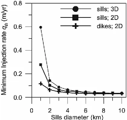
Low aspect-ratio intrusions, such as 8-km sills, lose an insignificant amount of heat from their tips relative to that transferred through their walls. Because the heat is mostly transferred in the direction normal to the largest dimensions of the sheet, the cooling time is controlled by the thickness of the sheet and not by its volume. This effect can be best seen if our results are expressed in terms of 1-D injection rates, qth, instead of volumetric rates. Such 1-D injection
rates represent the velocities of sheet accretion in meters per year. On Figure 6, qth vs.
intrusion diameters are plotted for sill and dike simulations in 2-D and quasi-3-D. The results are converging for intrusions of 6 km in diameter or more with no significant differences between sill and dike geometries. For lower diameters, the differences between sills and dikes are due to the difference in the localization of injection, which is floor of the magma chamber, i.e., close to the cold country rock, for sills (Figures 2d and 3), and center of the intrusive body (Figure 2b), i.e., far from the cold country rock, for dikes. We have run 2-D tests where each successive sill is injected in the center of the former ones and the results obtained overlap those for dikes. Figure 6 confirms that for low enough intrusions aspect ratios, the thermal evolution of magmatic system is independent of the diameter of intrusions and is controlled by the 1-D accretion rate.
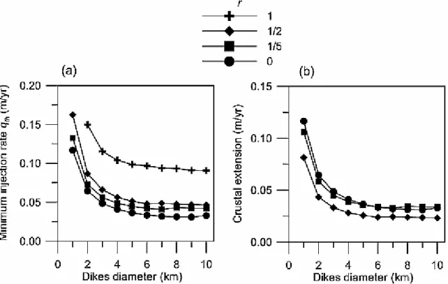
Figures 7a and 8 show how the minimum injection rate qth required to keep the magma
chamber above 875°C varies with the diameter of dikes and sills, respectively, and with the ratio r of eruption over intrusion. In the case of constant volume magma chamber (r = 1), each successive intrusion is in contact with the country rock and the system requires a higher injection rate than a growing magma chamber (r < 1), where new intrusions are in contact with former intrusions (Figures 5b, 7a, and 8). The result in terms of minimum injection rate qth is not significantly affected by the ratio of eruption over intrusion as long as this ratio is
less than one, because for r < 1 each new intrusion is insulated from the country rock by the former intrusions.
When dikes are modeled, the depth of the dike center is fixed at 8 km and different dike heights are tested. For r = 1, and if the dike diameter is 1 km, no solution is obtained with the numerical simulation, i.e., no injection rate less than 50 m/a can maintain 0.3 km3 of magma
above 875°C. We have tested models for dikes from 1 to 10 km in diameter. We note
however that the experimental data on pressure of crystallization [Martel et al., 1999] do not support a dike bottom deeper than 10 km and a dike top shallower than 6 km, i.e., a dike height much larger than 4 km. For the longest modeled dikes the minimum injection rate is 3 cm/a; for dikes 4 km in diameter the minimum injection rate is 4 cm/a. For each value of qth
and r, the extension of the crust needed to create space for the dikes can be calculated by subtracting the proportion of erupted volumes from the injection rate. For r = 1, the extension is 0 as all intruded volume is eventually erupted. For r = 1/2, the extension of the crust needed to accommodate the dikes is at least 2.5 cm/a (Figure 7b). For smaller r the corresponding extension is larger (Figure 7b). However the capacity of the crust to accommodate volumes of magma at high rates is limited. Maximum fault slip rates in arcs reported in the literature are around 3 cm/a, suggesting that an extension of more than 3 cm/a cannot be accommodated [Jarrard, 1986; Paterson and Tobisch, 1992; Yoshinobu et al., 1998]. This suggests that a magma chamber with a dike geometry can be accommodated in an arc environment only if r is larger than 1/2, i.e., if most of the intruded volume is eventually erupted.
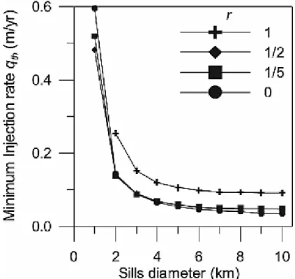
The results obtained with horizontal injections (sills) are illustrated in Figure 8. As for dikes, the minimum injection rates obtained for sills longer than 4 km and with r < 1 is 4 cm/a and the value of r does not affect the results provided r < 1. According to Cruden [1998], a magma body that forms by accretion of horizontal intrusions can be emplaced at high rate (up to several meters per year) by floor depression and exchange of magma with a deeper deflating reservoir. However, if r < 1 and emplacement rate is high, the accumulation of sills can result in intruded bodies that are unrealistically thick. We discuss in the next section how the body thickness can be used to limit the injection rate.
5.1.2. Limits of Erupted Volumes on Injection Rates
If we take 0.3 km3 [Fichaut et al., 1989] as the average volume per eruption, the total volume erupted by 34 eruptions over 13,500 years is about 10.2 km3, corresponding to an average eruption rate qe of 7.5 × 10⁻⁴ km3/a. This is more than the minimum flux of 4–5 × 10⁻⁴ km3/a
needed to maintain a spherical magma chamber above 875°C, which suggests that a spherical magma chamber can be maintained below Mount Pelee. However, as discussed before, if the magma chamber builds up by addition of low aspect ratio sheets, the controlling parameter is the 1-D accretion rate instead of the volume flux of magma. In order to compare the flux erupted with calculated minimum injection rate qth and put limits on the conditions that allow
the growth of a persistent magma chamber, volumes erupted are converted in 1-D injection rate qV for different intrusion radius L and eruption over intrusion ratio r:
qV strongly depends on the unknown intrusion radius. In order to maintain 0.3 km3 of magma
above 875°C, qV must be higher than the minimum injection rate qth that has been determined
on the basis of thermal constraints. If qV is smaller than qth, the magma chamber cools down
and crystallizes between two recharges.
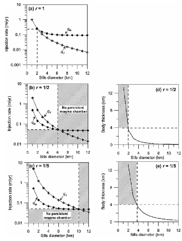
For r = 1, the curves of qth and qV are tangential and the conditions needed to keep a persistent
magma chamber (i.e., qV ≥ qth) are only reached for intrusion of about 2 km in diameter
injected at rate of at least 25 cm/a (Figure 9a). For r < 1, the magma body is growing with time. For magma body that grows by accretion of sills, the total thickness of intruded magma during the third cycle of Mount Pelee is qV (the rate of magma intruded) minus qe (the rate of
magma erupted) multiplied by 13,500 years (Figures 9d and 9e). For smalls sills and corresponding high qV, the intrusive body becomes unrealistically thick (>4 km; Figures 9d
and 9e) and magma chamber depths do not fit the pressures determined by experimental petrology, which further limits possible sill dimensions and injection rates. The limitations imposed by intrusive body thickening and by thermal requirements indicate that for r = 1/2 (i.e., intruded flux is 15 × 10−4 km3/a) sill diameters and injection rates needed for the presence of a persistent magma chamber are in the range of 2 to 6 km and 4 to 50 cm/a and, for r = 1/5 (i.e., intruded flux is 37.5 × 10⁻⁴ km3/a), in the range of 4 to 10 km and 4 to 20 cm/a. These results are based on an eruptive flux of 7.5 × 10⁻⁴ km3/a. This flux may be underestimated since edifice flank collapse are known at Mt. Pelee [Le Friant et al., 2003], and it is possible that ash and tephra fell into the sea during plinian activity. If an erupted flux qe of 15 × 10−4 km3/a is assumed (instead of 7.5 × 10⁻⁴ km3/a), higher qV are obtained
(equation (7)) and the condition of qV ≥ qth is satisfied for longer sills, i.e., 2 to 4 km for r = 1,
3 to 9 km for r = 1/2 and 5 to 14 km for r = 1/5. However, the minimum emplacement rate is limited by qth and is 4 cm/a independently of the assumed erupted flux. The average time
interval between two eruptions is 400 years (34 eruptions in 13,500 years), thus a range of possible injection rates of 4–50 cm/a implies that the thickness of magma from depth that is added to the magma chamber between eruptions is in the range of 16 to 200 m.
5.2. Evolution of the Volume of Magma With a Fixed Injection Rate
To obtain the minimum injection rate qth, we have forced the modeled system to keep the
critical volume (0.3 km3) of magma above 875°C, which resulted in an injection rate that varies with time as the crust heats up. As the injection rate is probably controlled by the dynamics of the magma source at depth and not by the state of the upper crustal magma chamber, a fixed injection rate is more realistic. With the simulation as illustrated in Figure 1b, the injection rate is kept constant over time producing variable volumes of eruptible magma (above 875°C).
Figure 10a illustrates the case where sills 4 km in diameter are emplaced at the bottom of the magma chamber at a rate of 12 cm/a. Half of the magma injected in the magma chamber is erupted (r = 1/2). At the beginning of the simulation, the system is cold and the rate of magma chamber replenishment is not high enough to keep the chamber above 875°C. Each magma injection crystallizes before the next one. With successive injections, the system heats up and
after an incubation time of 13,000 years, eruptible magma starts to accumulate and the magma chamber becomes persistently active. For lower injection rates, less heat is advected in the system resulting in longer incubation times (Figure 10b) and when the injection rate is close to qth, no persistent magma chamber can form on timescales smaller than 125,000 years
(Figure 10c). Note that for the 3 simulations illustrated in Figure 10, sill diameters change for each simulation so that although the injection rates in meters per year are different, the
volume flux is close to 15 × 10−4 km3/a for all simulations. These results clearly show that the ability of a magma chamber that builds up by accretion of low aspect ration sheets to be persistently active is controlled by the rate of sheet accretion and not by the injected volumes.
Figure 11 shows temperatures and melting degrees in the modeled system (country rocks + magma intrusions) after sills 5 km in diameter were injected at a rate of 8 cm/a over 62,500 years. The ratio of eruption over intrusion was 1/2 and the thickness intruded was 2.5 km. Successive sills were injected at the lower rheological boundary between the mush (melt fraction < 0.4) and the liquid magma (melt fraction >0.4). The reservoir of eruptible magma (T > 875°C, melt fraction >0.6) is small (V = ~4.5 km3) compared to the partially molten body (melt fraction >0, V = ~17 km3), which itself is significantly smaller than the intruded body (V = 50 km3). The country rock below the intrusion is partially molten, but not the roof, nor the walls (Figure 11). In the model, the country rock has the same temperature-melt fraction relationship as the injected magma. Partial melting of the country rock would be less important if the country rock were more refractory, for example if it had lost H2O. Note that
in a convecting magma chamber the distribution of melts might be slightly different and we would expect the proportion of the eruptible magma relative to the solidified magma to be lower as convection increases heat transfer and cooling.
5.3. Advective Processes
All previous calculations were done for a system with no mass transfer (pure conduction; e.g., Figure 11). In nature though, heat transfer can be accelerated within the magma by thermal convection [e.g., Couch et al., 2001; Davaille and Jaupart, 1993; Huppert and Sparks, 1988a; Jellinek and Kerr, 1999; Martin et al., 1987; Sparks et al., 1984] and gas sparging [Bachmann and Bergantz, 2006], and within the country rock by hydrothermal convection [e.g., Cathles et al., 1997]. The replenishment of the magma chamber may be followed by a period of
convection as the resident magma is heated up by the new hot magma before a longer period of conductive heat loss [Koyaguchi and Kaneko, 1999, 2000]. The thermal convection contributes to heat transfer in parts of the magma chamber that are largely molten, with a crystal fraction that is lower than the critical crystal fraction of 40–60% [Lejeune and Richet, 1995; Marsh, 1981; Vigneresse et al., 1996] beyond which flow is prevented. In contrast, the heat transfer by gas sparging is effective in the mushy part of the chamber and especially efficient when crystallinities are 50–70% (high permeabilities for gas flow).
Extremely vigorous thermal convection is approximated in our simulations by instantaneously homogenizing the temperature of cells that are above 875°C (Figure 12). The minimum injection rates in these conditions are slightly higher than those obtained with fully conductive simulations (i.e., 6 cm/a instead of 4 cm/a for low aspect ratio sills and a growing magma chamber). The intrusion diameters can be one kilometer smaller and still allow for a persistent magma chamber. The convection as modeled here is an end-member in term of heat transfer enhancement thus our results suggest that magma convection does not affect significantly the minimum injections rates needed to maintain a persistent magma chamber.
For gas sparging, numerical simulations [Bachmann and Bergantz, 2006] showed that, to first order, heat transfer can be doubled by upward percolation of bubbles within the magma chamber. The effect of sparging could potentially be larger if gas streaming (concentration of bubbles as plumes in high-permeability channels) can occur [e.g., Phillips and Woods, 2002; Thomas et al., 1993], which was not taken into consideration by the 1-D simulations of Bachmann and Bergantz [2006]. However, as natural examples do not provide clear evidence of streaming (the amount of partial remelting in mineral assemblages of natural samples affected by sparging appears fairly constant), we suggest that the 1-D simulations of
Bachmann and Bergantz [2006] provide a reasonable first-order heat transfer model. We did not explicitly model gas sparging in this paper but estimated its possible effect by doubling heat transfer in parts of the magma chamber where the crystal fraction is between 50 and 70%. As shown in Figure 12, the thermal effect of gas sparging on the total heat budget is even more limited than thermal convection, especially for long sills. Thus, magma-related advective processes have a modest influence on the overall heat balance under Mount Pelee.
In the case of Mount Pelee, surface manifestations of hydrothermal circulation are scarce, although the existence of a (small) geothermal system cannot be excluded [Traineau et al., 1989]. The occurrence of hydrothermal circulation would result in an increase of the heat transfer in the country rock. Such an increase requires raising the injection rate. The
magnitude of heat transfer enhancement by hydrothermal convection could potentially reach a couple of orders of magnitude for shallow magma chambers and high-permeability country rocks [Stimac et al., 2001; Wohletz et al., 1999]. Convective circulation may dominate conduction to depths of more than 8 km if the permeabilities exceed 10−18 m2 [Norton and
Taylor, 1979; Travis et al., 1991]. However in the vicinity of the magma chamber, at
temperatures above 350°C, permeabilities may be reduced and convection prevented because of the closure of cracks owing to mineral dissolution and precipitation [Smith and Evans, 1984; Tenthorey and Fitz Gerald, 2006]. We have tested the possible effect of hydrothermal circulation by increasing the heat transfer in the country rock by a factor of 5 and found a minimum injection rate of 13 cm/a instead of 4.7 cm/a for the fully conductive model (sills diameter = 8 km, r = 1/2). As expected, country-rock-related advective processes have more impact than those related to the magma chamber, owing to the large volume of country rock available for heat dissipation. Thus in a system that is cooled by hydrothermal circulation, the curves of qth in Figure 9 would be shifted toward higher values putting stronger limits on the
sills diameter consistent with the existence of a persistent magma chamber.
6. Discussion
For a magma chamber that is spherical, the flux of magma needed to maintain the magma chamber above 875°C is about 4–5 × 10⁻⁴ km3/yr. For a magma chamber that builds up by accretion of low aspect ratio sheets accretion, keeping a minimum volume at eruptible temperature does not depend on the volumes injected but on the rate of sheets accretion. In this case, the formation of a persistent magma chamber at 2 kbar below Mount Pelee requires a range of magma injection rate and magma chamber dimensions that are limited by (1) the heat loss through the crust and (2) the observed erupted volumes. Table 2 summarizes the results obtained for a magmatic system where most of the magma injected in the chamber is eventually erupted and a system where at least half of the injected magma stays in the magma chamber. We note that if erupted volumes were underestimated (or overestimated) the
possible intrusion diameters would be shifted toward higher (or lower) values, however the minimal injection rate computed on the basis of heat transfer computation would not be changed because it is controlled by the cooling rate of successive intrusions and not by the
volume of magma present in the chamber. A minimum value of accretion rate of about 4 cm/a is found irrespective of the geometry of the feeding system, either dikes or sills. However, the implications for Mount Pelee magma chamber are markedly dependent on the particular geometry considered. In the case of magma injection through dikes, the minimum injection rate necessary to maintain a permanently eruptible magma volume is in the same range as the maximum rate of deformation of the upper crust. Therefore, it is unlikely that magma and heat can be advected in amounts necessary to make a large persistent magma chamber in the case of dike geometry. In contrast, in the case of sill geometry, the necessary volume associated with magma emplacement rates >4 cm/a can be found elsewhere, and so there is no limitation to the development of a persistently eruptible magma chamber. These contrasted conclusions provide an a posteriori validation of the need to consider different chamber geometries, as done in this paper. The difficulty to stabilizing a magma chamber with dikes does not necessarily rule out this particular geometry. Our results can account for the geometry described by Pichavant et al. [2002, Figure 5], where magma stalls and equilibrates at a pressure of 2 kbar in a vertical conduit. However our modeling results impose that the volume of magma that is injected at this level from depth does not greatly exceed the erupted
volumes. It also requires that the height of the conduit that is drained by eruptions is about 2 km.
Our results are in close agreement with those obtained by Hanson and Glazner [1995], who found that extension rates between 1 and 4 cm/a are needed to form and maintain a magma chamber, and by Yoshinobu et al. [1998] who found that the formation of a midcrust magma chamber requires an emplacement rate of 2.5–5 cm/a and an incubation time of 30 ka. The similarities in the results of these independent studies confirm that the results are not sensitive to the details of the modeling and input parameters and thus are applicable to systems
elsewhere.
The magma production in the Antilles arc is particularly low owing to the slow movement of the subducting plate [Macdonald et al., 2000]. In other arcs, volumes of magma transiting through the crust are more important. We note that the emplacement rates of magma in the upper crust inferred from this study and from studies by Yoshinobu et al. [1998] and by Hanson and Glazner [1995] are one order of magnitude larger than those that are used in numerical models of heat transfer in magmatic system in the lower crust [Annen and Sparks, 2002; Annen et al., 2006a; Dufek and Bergantz, 2005]. However, the models of deep system involve processes on the scale of arc segments and on timescales of millions years, whereas in this study we estimate emplacement rates at the scale of a single volcano.
Our values of minimum injection rate of a few centimeters per year based on thermal constraints are conservative as possible cooling owing to hydrothermal circulation is neglected. In cases where a hydrothermal system efficiently cools down the crust, forming and maintaining an active magma chamber would require very high emplacement rates of tens of centimeters per year. Alternatively, in some cases, the volcanism may not be associated with a persistent upper crustal magma chamber. This would imply that magma is generated in the lower crust and directly ascents toward the surface [Annen et al., 2006a] or stalls in the upper crust before being erupted on timescales that are lower than the time interval between two eruptions. Lipman [2007] recognizes that in some arcs, the magma may come from the mid or lower crust without involving shallow magma chambers. This model is supported by the lack of detected ground deformation associated with eruptions of several Andeans volcanoes that suggests the absence of magma chamber at depth shallower than about 20 km [Pritchard and Simons, 2004].
In the central Andes, ground deformations in the range of 1–2 cm/year are observed. These deformations are not associated with eruptions [Pritchard and Simons, 2004]. Inversions of these data suggest that the volumes associated with the deformation are 20–40 × 106 m3/a for sources located between 8 and 25 km depth [Pritchard and Simons, 2004]. According to our models, such magma flux can lead to the growth of active magma chambers, especially at depths where the cooling owing to hydrothermal circulation is probably limited.
If a significant part of the magma does not erupt, a long-lived magma chamber can form after an incubation time. If emplacement rate is low, a long incubation time is needed during which large volumes of magma are intruded and solidify. If emplacement rate is fast, incubation time is shorter but also involves large intruded volumes. Geochronological data suggest that some plutons and batholiths that are several kilometers thick were emplaced over several millions years, i.e., that their average emplacement rate was only a few millimeters per year [Coleman et al., 2004; Deniel et al., 1987; Matzel et al., 2006]. This led Glazner et al. [2004] to suggest that plutons are not large frozen magma tanks. Indeed, heat transfer calculations show that at such low emplacement rates, a protracted incubation time and intrusion of several kilometers of magma are needed before an active magma chamber with a volume larger than a single intrusion can form [Annen et al., 2006b] and this magma chamber would only represent a minor part of the total intruded magma volume. Thus, the growth of large reservoirs of mobile magma requires transient acceleration of the emplacement rate well above the rate averaged over plutons emplacement duration. For example, Matzel et al. [2006] found that the emplacement duration of Mount Stuart batholith was 5.5 Ma but was punctuated by periods of high magma flux on the timescale of a few hundred to thousands of years.
7. Conclusions
We explored the conditions needed to maintain a persistent magma chamber below Mount Pelee and explain the petrological homogeneity of the products erupted over the last 13,500 years. We presented an analytical model describing the thermal evolution of a spherical magma chamber surrounded by an initially cold crust and replenished with a variable supply of fresh magma. This simple model suggests that a magma flux of about 4–5 × 10⁻⁴ km3/a is needed to maintain 0.3 km3 of magma above 875°C at a depth of 8 km. This minimum estimate is below, and thus in agreement with, the inferred flux of erupted magmas of 7.5 × 10⁻⁴ km3/a.
If, however, the magma chamber builds up as most plutons by accretion of low aspect ratio sheet intrusions, the ability of intrusions to maintain a chamber of a given size does not depend on the volumetric magma flux, but on the rate of sheets accretion. Numerical models of conductive heat transfer and the limits imposed by field observations and experimental petrology indicate that in the case of Mount Pelee and for an erupted flux in the range of 7.5– 15 × 10−4 km3/a:
1. A persistent magma chamber that does not crystallize below 875°C between two
replenishments requires a minimum injection rate of 4 cm/a and sheets that are less than 15 km in diameter.
2. For intrusive sheets that are horizontal (sills), the thickness of the intrusive body is realistic (<4 km) if injection rates are less than 50 cm/a and the sill diameters are more than 2 km.
3. Because the minimum injection rate exceeds the extension rates that are realistic in an arc environment, a persistent magma chamber is unlikely to form by accretion of dikes unless the diameter of the dikes is about 2 km and most of the magma injected in the magma chamber is eventually erupted.
4. The growth of a persistent magma chamber fed by sills accreted at a fixed rate of a few centimeters per year requires an incubation time of tens of thousands years.
5. After 62,500 years of injection at a rate of a few centimeters per year, more than 65% of the magma injected has completely solidified, and less than 10% has temperatures and melt fractions corresponding to the erupted products. The rest forms a highly crystallized mush.
6. Possible cooling of the magma chamber by hydrothermal circulation would strongly limit its ability to stay above 875°C between eruptions.
Appendix A
Figure A1. Elemental volume for computation of heat transfer using cylindrical coordinates. Enhanced EPS
Discretization with a finite volume approach of heat transfer equation in cylindrical coordinates (Figure A1) yields:
Discretization with a finite volume approach of heat transfer equation in cylindrical coordinates (Figure A1) yields:
q1 to q6 are the heat fluxes through the six sides of the elemental volume (Figure A1), r and
are radius and azimuth respectively, ρ is density, cp is heat capacity, Δt is time increment, T is
temperature, L is latent heat and X is melt fraction.
For sills emplacement, the system is axisymetric so that q5 = q6 = 0, ΔΘ simplifies and the 3-D system reduces to a 2-3-D system where:
The subscripts i, j denote the position of the cells in the two dimensions of space. Below the solidus temperature, ΔX = 0 and
k is the thermal diffusivity.
Between the liquidus and solidus,
Because ΔX is a nonlinear function of T (Figure 4), equation (A7) is solved iteratively with a bisection method and a precision of 10–12°C. The stability condition is Δt < Δr2/4k
In case of dikes, because the sheet axis of symmetry is perpendicular to the geothermal gradient, the system is not axisymetric and the simulations were run in 2-D with Cartesian coordinates:
Δx is cell dimension. The equations for q1, q2, q3, and q4 and for the stability conditions are
identical to equations (A2)–(A5) with Δx substituting for Δr. Below solidus:
The difference approximation of the derivative is of second order for space and first order for time. To reduce round off errors the simulations were run with variables of extended type with 19 digits.
Acknowledgments
The authors thank Steve Sparks for comments on the manuscript that significantly
strengthened this paper. Catherine Ginibre helped us to clarify the text. The paper benefited from stimulating discussions with Jon Blundy and Thierry Menand on magma chambers and conduit dynamics and from the reviews of Drew Coleman, Mark Jellinek, and an anonymous reviewer. This study was financially supported by the DYETI and ANR (project UD Antilles) programs.
References
Annen, C., and R. S. J. Sparks (2002), Effects of repetitive emplacement of basaltic intrusions on thermal evolution and melt generation in the crust, Earth Planet. Sci. Lett., 203(3–4), 937– 955.
Annen, C., J. D. Blundy, and R. S. J. Sparks (2006a), The genesis of intermediate and silicic magmas in deep crustal hot zones, J. Petrol., 47(3), 505–539, doi:10.193/petrology/egi084.
Annen, C., B. Scaillet, and R. S. J. Sparks (2006b), Thermal constraints on the emplacement rate of a large intrusive complex: The Manaslu Leucogranite, Nepal Himalaya, J. Petrol., 47(1), 71–95, doi:10.1093/petrology/egi068.
Bachmann, O., and G. W. Bergantz (2006), Gas percolation in upper-crustal silicic crystal mushes as a mechanism for upward heat advection and rejuvenation of near-solidus magma bodies, J. Volcanol. Geotherm. Res., 149(1–2), 85–102.
Baehr, H. D., and K. Stephan (2006), Heat and Mass Transfer, 2nd ed., 688 pp., Springer, New York.
Bellon, H., B. Pelletier, and D. Westercamp (1974), Geochronometric data relative to
volcanisms of Martinique, C. R. Hebdomadaires Seances Acad. Sci. Ser. D, 279(6), 457–460.
Blake, S., and N. Rogers (2005), Magma differentiation rates from (226Ra/230Th) and the size and power output of magma chambers, Earth Planet. Sci. Lett., 236(3–4), 654–669.
Blundy, J. D., and R. S. J. Sparks (1992), Petrogenesis of mafic inclusions in granitoids of the Adamello massif, Italy, J. Petrol., 33(5), 1039–1104.
Bohrson, W. A., and F. J. Spera (2001), Energy-constrained open system magmatic processes II: Application of energy-constrained assimilation-fractional crystallization (EC-AFC) model to magmatic systems, J. Petrol., 42(5), 1019–1041.
Cathles, L. M., A. H. J. Erendi, and T. Barrie (1997), How long can a hydrothermal system be sustained by a single intrusive event?, Econ. Geol., 92(7–8), 766–771.
Clauser, C., and E. Huenges (1995), Thermal conductivity of rocks and minerals, in Rock Physics and Phase Relations: A Handbook of Physical Constants, edited by T. J. Ahrens, pp. 105–126, AGU, Washington, D. C.
Coleman, D. S., W. Gray, and A. F. Glazner (2004), Rethinking the emplacement and evolution of zoned plutons: Geochronologic evidence for incremental assembly of the Tuolumne Intrusive Suite, California, Geology, 32(5), 433–436.
Couch, S., R. S. J. Sparks, and M. R. Carroll (2001), Mineral disequilibrium in lava explained by convective self-mixing in open magma chambers, Nature, 411, 1037–1039.
Cruden, A. R., and K. J. W. McCaffrey (2001), Growth of plutons by floor subsidence: Implications for rates of emplacement, intrusion spacing and melt-extraction mechanisms, Phys. Chem. Earth Part A, 26(4–5), 303–315.
Davaille, A., and C. Jaupart (1993), Transient high-Rayleigh-number thermal-convection with large viscosity variations, J. Fluid Mech., 253, 141–166.
Deniel, C., P. Vidal, A. Fernandez, P. Le Fort, and J. J. Peucat (1987), Isotopic study of the Manaslu granite (Himalaya, Nepal): Inferences on the age and source of Himalayan
leucogranites., Contrib. Mineral. Petrol., 96, 78–92.
de Saint-Blanquat, M., R. D. Law, J. L. Bouchez, and S. S. Morgan (2001), Internal structure and emplacement of the Papoose Flat pluton: An integrated structural, petrographic, and magnetic susceptibility study, Geol. Soc. Am. Bull., 113(8), 976–995.
de Saint-Blanquat, M., G. Habert, E. Horsman, S. S. Morgan, B. Tikoff, P. Launeau, and G. Gleizes (2006), Mechanisms and duration of non-tectonically assisted magma emplacement in the upper crust: The Black Mesa pluton, Henry Mountains, Utah, Tectonophysics, 428(1–4), 1–31.
Dufek, J., and G. W. Bergantz (2005), Lower crustal magma genesis and preservation: A stochastic framework for the evaluation of basalt-crust interaction, J. Petrol., 46(11), 2167– 2195.
Fichaut, M., R. C. Maury, H. Traineau, D. Westercamp, J. L. Joron, A. Gourgaud, and C. Coulon (1989), Magmatology of Mt. Pelee (Martinique, F.W.I): 3. Fractional crystallization versus magma mixing, J. Volcanol. Geotherm. Res., 38(1–2), 189–213.
Glazner, A. F., J. M. Bartley, D. S. Coleman, W. Gray, and Z. T. Taylor (2004), Are plutons assembled over millions of years by amalgamation from small magma chambers?, GSA Today, 14(4/5), 4–11.
Hanson, R. B., and A. F. Glazner (1995), Thermal requirements for extensional emplacement of granitoids, Geology, 23(3), 213–216.
Hawkesworth, C. J., S. Blake, P. Evans, R. Hugues, R. MacDonald, L. E. Thomas, S. P. Turner, and G. Zellmer (2000), Time scales of crystal fractionation in magma chambers— Integrating physical, isotopic and geochemical perspectives., J. Petrol., 41(7), 991–1006.
Holbrook, W. S., W. D. Mooney, and N. I. Christensen (1992), The seismic velocity structure of the deep continental crust, in Continental Lower Crust, edited by D. M. Fountain et al., pp. 1–43, Elsevier, New York.
Holman, J. P. (1997), Heat Transfer, 8th ed., 696 pp., McGraw-Hill, New York.
Huppert, H. E., and R. S. J. Sparks (1988a), Melting of the roof of a chamber containing a hot, turbulently convecting fluid, J. Fluid Mech., 188, 107–131.
Huppert, H. E., and S. J. Sparks (1988b), The generation of granitic magma by intrusion of basalt into continental crust, J. Petrol., 29(3), 599–624.
Jarrard, R. D. (1986), Relations among subduction parameters, Rev. Geophys., 24(2), 217– 284.
Jellinek, A. M., and R. C. Kerr (1999), Mixing and compositional stratification produced by natural convection: 2. Applications to the differentiation of basaltic and silicic magma chambers and komatiite lava flows, J. Geophys. Res., 104(B4), 7203–7218.
Koyaguchi, T., and K. Kaneko (1999), A two-stage thermal evolution model of magmas in continental crust, J. Petrol., 40(2), 241–254.
Koyaguchi, T., and K. Kaneko (2000), Thermal evolution of silicic magma chambers after basalt replenishments, Trans. R. Soc. Edinburgh Earth Sci., 91, 47–60.
La Delfa, S., G. Patane, R. Clocchiatti, J. L. Joron, and J. C. Tanguy (2001), Activity of Mount Etna preceding the February 1999 fissure eruption: Inferred mechanism from seismological and geochemical data, J. Volcanol. Geotherm. Res., 105(1–2), 121–139.
Lees, J. M. (2007), Seismic tomography of magmatic systems, J. Volcanol. Geotherm. Res., 17, 37–56, doi:10.1016/j.jvolgeores.2007.06.08.
Le Friant, A., G. Boudon, C. Deplus, and B. Villemant (2003), Large-scale flank collapse events during the activity of Montagne Pelée, Martinique, Lesser Antilles, J. Geophys. Res., 108(B1), 2055, doi:10.1029/2001JB001624.
Lejeune, A. M., and P. Richet (1995), Rheology of crystal-bearing silicate melts—An experimental study at high viscosities, J. Geophys. Res., 100(B3), 4215–4229.
Lipman, P. W. (2007), Incremental assembly and prolonged consolidation of Cordilleran magma chambers: Evidence from the southern Rocky Mountain volcanic field, Geosphere, 3(1), 42–70.
Macdonald, R., C. J. Hawkesworth, and E. Heath (2000), The Lesser Antilles volcanic chain: A study in are magmatism, Earth Sci. Rev., 49(1–4), 1–76.
Marsh, B. D. (1981), On the crystallinity, probability of occurrence, and rheology of lava and magma, Contrib. Mineral. Petrol., 78(1), 85–98.
Martel, C., M. Pichavant, J. L. Bourdier, H. Traineau, F. Holtz, and B. Scaillet (1998), Magma storage conditions and control of eruption regime in silicic volcanoes: Experimental evidence from Mt. Pelee, Earth Planet. Sci. Lett., 156(1–2), 89–99.
Martel, C., M. Pichavant, F. Holtz, B. Scaillet, J.-L. Bourdier, and H. Traineau (1999), Effects of fO2 and H2O on andesite phase relations between 2 and 4 kbar, J. Geophys. Res., 104(B12), 29,453–29,470.
Martin, D., R. W. Griffiths, and I. H. Campbell (1987), Compositional and thermal convection in magma chambers, Contrib. Mineral. Petrol., 96(4), 465–475.
Martin-Del Pozzo, A. L., G. Cifuentes, E. Gonzalez, A. Martinez, and F. Mendiola (2008), Magnetic signatures associated with magma ascent and stagnation at Popocatepetl volcano,
Mexico: Implications for eruption triggering mechanisms during 2006, in Dynamics of Crustal Magma Transfer, Storage and Differentiation, edited by C. Annen and G. F. Zellmer, Geol. Soc., London, in press.
Matzel, J. E. P., S. A. Bowring, and R. B. Miller (2006), Time scales of pluton construction at differing crustal levels: Examples from the Mount Stuart and Tenpeak intrusions, North Cascades, Washington, Geol. Soc. Am. Bull., 118(11–12), 1412–1430.
Miller, C. F., and J. S. Miller (2002), Contrasting stratified plutons exposed in tilt blocks, Eldorado Mountains, Colorado River Rift, NV, USA, Lithos, 61(3–4), 209–224.
Nagle, F., J. J. Stipp, and D. E. Fisher (1976), K-Ar geochronology of limestone caribbees and Martinique, Lesser Antilles, West Indies, Earth Planet. Sci. Lett., 29(2), 401–412.
Norton, D., and H. P. Taylor (1979), Quantitative simulation of the hydrothermal systems of crystallizing magmas on the basis of transport-theory and oxygen isotope data—Analysis of the Skaergaard Intrusion, J. Petrol., 20(3), 421–486.
Paterson, S. R., and O. T. Tobisch (1992), Rates of processes in magmatic arcs—Implications for the timing and nature of pluton emplacement and wall rock deformation, J. Struct. Geol., 14(3), 291–300.
Petford, N., A. R. Cruden, K. J. W. McCaffrey, and J.-L. Vigneresse (2000), Granite magma formation, transport and emplacement in the Earth's crust, Nature, 408, 669–673.
Phillips, J. C., and A. W. Woods (2002), Suppression of large-scale magma mixing by melt-volatile separation, Earth Planet. Sci. Lett., 204(1–2), 47–60.
Pichavant, M., C. Martel, J. Bourdier, and B. Scaillet (2002), Physical conditions, structure, and dynamics of a zoned magma chamber: Mount Pelée (Martinique, Lesser Antilles Arc), J. Geophys. Res., 107(B5), 2093, doi:10.1029/2001JB000315.
Piwinskii, A. J., and P. J. Wyllie (1968), Experimental studies of igneous rock series—A zoned pluton in Wallowa Batholith Oregon, J. Geology, 76(2), 205–234.
Pritchard, M. E., and M. Simons (2004), An InSAR-based survey of volcanic deformation in the central Andes, Geochem. Geophys. Geosyst., 5, Q02002, doi:10.1029/2003GC000610.
Reiners, P. W., B. K. Nelson, and M. S. Ghiorso (1995), Assimilation of felsic crust by basaltic magma—Thermal limits and extents of crustal contamination of mantle-derived magmas, Geology, 23(6), 563–566.
Robertson, E. C. (1988), Thermal properties of rocks, U.S. Geol. Surv. Open File Rep., 88-441, 106 pp.
Smith, D. L., and B. Evans (1984), Diffusional crack healing in quartz, J. Geophys. Res., 89(B6), 4125–4135.
Sparks, R. S. J., H. E. Huppert, and J. S. Turner (1984), The fluid-dynamics of evolving magma chambers, Philos. Trans. R. Soc. London Ser. A, 310(1514), 511–534.
Stimac, J. A., F. Goff, and K. Wohletz (2001), Thermal modeling of the Clear Lake magmatic-hydrothermal system, California, USA, Geothermics, 30(2–3), 349–390.
Tannehill, J. C., D. A. Anderson, and R. H. Pletcher (1997), Computational Fluid Mechanics and Heat Transfer, 792 pp., Taylor and Francis, Philadelphia, Pa.
Tenthorey, E., and J. D. Fitz Gerald (2006), Feedbacks between deformation, hydrothermal reaction and permeability evolution in the crust: Experimental insights, Earth Planet. Sci. Lett., 247(1–2), 117–129.
Thomas, N., S. Tait, and T. Koyaguchi (1993), Mixing of stratified liquids by the motion of gas-bubbles—Application to magma mixing, Earth Planet. Sci. Lett., 115(1–4), 161–175.
Thompson, A. B., L. Matile, and P. Ulmer (2002), Some thermal constraints on crustal assimilation during fractionation of hydrous, mantle-derived magmas with examples from central alpine batholiths, J. Petrol., 43(3), 403–422.
Traineau, H., D. Westercamp, and Y. Benderitter (1989), Case study of a volcanic geothermal system, Mount Pelee, Martinique, J. Volcanol. Geotherm. Res., 38(1–2), 49–66.
Travis, B. J., D. R. Janecky, and N. D. Rosenberg (1991), Three-dimensional simulation of hydrothermal circulation at midocean ridges, Geophys. Res. Lett., 18(8), 1441–1444.
Vandermolen, I., and M. S. Paterson (1979), Experimental deformation of partially-melted granite, Contrib. Mineral. Petrol., 70(3), 299–318.
Vigneresse, J. L., P. Barbey, and M. Cuney (1996), Rheological transitions during partial melting and crystallization with application to felsic magma segregation and transfer, J. Petrol., 37(6), 1579–1600.
Vincent, P. M., J. L. Bourdier, and G. Boudon (1989), The primitive volcano of Mount
Pelee—Its construction and partial destruction by flank collapse, J. Volcanol. Geotherm. Res., 38(1–2), 1–15.
White, S. M., J. A. Crisp, and F. J. Spera (2006), Long-term volumetric eruption rates and magma budgets, Geochem. Geophys. Geosyst., 7, Q03010, doi:10.1029/2005GC001002.
Wiebe, R. A., and W. J. Collins (1998), Depositional features and stratigraphic sections in granitic plutons: Implications for the emplacement and crystallization of granitic magma, J. Struct. Geol., 20(9–10), 1273–1289.
Wohletz, K., L. Civetta, and G. Orsi (1999), Thermal evolution of the Phlegraean magmatic system, J. Volcanol. Geotherm. Res., 91(2–4), 381–414.
Yoshinobu, A. S., D. A. Okaya, and S. R. Paterson (1998), Modeling the thermal evolution of fault-controlled magma emplacement models: Implications for the solidification of granitoid plutons, J. Struct. Geol., 20(9–10), 1205–1218
Figures and Tables
Figure 1. Flowchart of the numerical simulations. (a) Computation of the minimum magma fluxes and injection rates needed to keep a volume of 0.3 km3 above 875°C. Inputs are the geometry of the system, the critical volume of magma that is kept above 875°C, and the duration of the simulation. Outputs are the volumetric magma fluxes and 1-D injection rates over time. (b) Fixed injection rate. Inputs are the injection rate, geometry of the system, and duration of simulation. Output is the volume of magma between 875 and 900°C over time. Enhanced EPS
Figure 2. Geometry of the model (not to scale). (a and b) Vertical intrusions (dikes); (c and d) horizontal intrusions (sills). The ratio of erupted over intruded volumes r is 1 in Figures 2a and 2c and less than 1 in Figures 2b and 2d. The numbers in Figure 2b indicate the sequence of dike injections, with dike number 1 being the first injected (the oldest). The temperatures are calculated at the nodes of the squared grid. The boundary conditions are fixed
temperatures; T is 20°C at surface and is as determined by the geotherm (20°C/km) at depth and on the right boundary. Enhanced EPS
Figure 3. Evolution with time of sill injection depth and of bottom of the intrusive body resulting from the accretion of sills. Injection rate is 8 cm/a, and the ratio of erupted over intruded volume is 1/2. Sills are injected at the lower boundary between the mush and the liquid magma (melt fraction >0.4). At the beginning of the simulation, over 24,000 years, the magma solidifies between injections and the sills are emplaced at the top of the body.
Figure 4. Relationship between melt fractions and temperatures (equation (6)). Between 876 and 930°C the curve is interpolated from experimental data, as represented by circles [Martel et al., 1999]. A constant melt H2O content of 6 wt% is assumed [Martel et al., 1998]. The
curve is linear between the solidus and 876°C and between the liquidus and 930°C. Solidus and liquidus temperatures are 760 and 990°C, respectively. Triangles correspond to
experimental data for a tonalite compositionally close to Mount Pelee andesites, as found by Piwinskii and Wyllie [1968]. Enhanced EPS
Figure 5. Evolution of the magma flux over time for dikes, sills, and a spherical magma chamber. (a) Sills are either emplaced at the lower limit between the mush and the liquid magma (floor of the magma chamber) or at the upper limit between the liquid magma and the mush (roof of the magma chamber). Sills and dikes are 4 km long. The simulations are run in cylindrical coordinates for the sills (quasi-3-D) and in Cartesian coordinates in 2-D for the dikes, which explains much of the difference observed between sill and dike simulations. The erupted volume is assumed to be very low relative to the intruded volume (r = 0). (b)
Intrusions are sills that are emplaced at the floor of the magma chamber. The results are given for different eruption over intrusion ratio r for sills that are 2 and 8 km in diameter. Curve fluctuations for r = 1/2 reflect cycles of heat flux related to magma removal from the system by eruption. The other model parameters are as reported in Table 1.
Figure 6. Comparison between injection rates obtained with 2-D and quasi-3-D simulations for sills and dikes, for r = 0. The results are converging for intrusion of 6 km in diameter and more, suggesting that for long intrusion the heat loss in the third dimension becomes
insignificant. The differences at low diameters between 2-D models for sills and dikes are due to different locations of emplacement for sills (chamber floor) and dike (middle of intrusion). If sills are emplaced in the middle of former intrusions as for dikes, the results overlap. Enhanced EPS
Figure 7. (a) Relationships between the minimum injection rates qth and the diameters of dikes
for different eruption over intrusion ratio r. Other model parameters are as reported in Table 1. (b) Crustal extension needed to accommodate the dikes obtained by subtracting the erupted portion from the injection rate. For r = 1, there is no crustal extension as all the magma intruded is erupted. Enhanced EPS
Figure 8. Relationships between minimum injection rates qth and the diameters of sills for
different eruption over intrusion ratio r. Other model parameters are as reported in Table 1. Enhanced EPS
Figure 9. (a, b, and c) Injection rates qth and qV and (d and e) intrusive body thicknesses after
13,500 years of intrusion computed for different sill diameters and ratio of eruptive-injected volumes r. Here qth is the minimum injection rate that is needed to grow a persistent magma
chamber, and qv is the injection rate calculated (equation (7)) assuming that the total volume
erupted by Mount Pelee over its last eruptive cycle is 10.2 km3 [Fichaut et al., 1989]. A persistent magma chamber can only grow below Mount Pelee for intrusion diameters and r values where the curve for qv is above the curve for qth. The body thickness is obtained by
subtracting the erupted portion from the injection rate qV and multiplying the result by the
duration of the last cycle (13,500 years). A body thickness of more than 4 km is considered unlikely. Enhanced EPS
Figure 10. Volume of eruptible magma in function of time and of the total injected thickness. In these simulations the injection rate is fixed (see Figure 1b). Eruptible magma is magma with temperatures above 875°C. The magma chamber grows by accretion of sills emplaced at the floor of the magma chamber. The ratio r of erupted over intruded volumes is 1/2.
Successive sills are 80 m thick. Each spike corresponds to an injection, but at the beginning of the simulation the cooling of sills can be faster than the sampling interval of the simulation (50 years), and all the injections do not appear on the diagrams. (a) The injection rate is 12 cm/a, and the sill diameters are 4 km. (b) The injection rate is 8 cm/a, and the sill diameters are 5 km. (c) The injection rate is 4 cm/a, and the sill diameters are 7 km. The injected volumetric fluxes (~15 × 10−4 km3/a) are similar for Figures 10a–10c. Enhanced EPS
Figure 11. Contours of (a) temperatures and (b) melt fractions. Sills 5 km in diameter were emplaced at an average rate of 8 cm/a (flux = 15.7 × 10⁻⁴ km3/a) over 62,500 years, as in Figure 10b. The sill emplacement level is at the floor of the magma chamber, and the ratio r of erupted over intruded volumes is 1/2. The dashed lines show the boundary between the successive injected sills and the country rock. Enhanced TIF
Figure 12. Comparison of minimum injection rates qth obtained with fully conductive models
with models where the effect of gas sparging is approximated by doubling heat transfer in the mush and with convective models. In convective models, temperatures in the mobile magma are instantaneously homogenized. In this example, r is 1/2, but results are comparatively similar with r = 1 or r = 1/5. Enhanced EPS

![Figure 4. Relationship between melt fractions and temperatures (equation (6)). Between 876 and 930°C the curve is interpolated from experimental data, as represented by circles [Martel et al., 1999]](https://thumb-eu.123doks.com/thumbv2/123doknet/14451688.518727/28.892.107.753.104.560/figure-relationship-fractions-temperatures-equation-interpolated-experimental-represented.webp)