Research Summary advanced materials analysis
How would you…
…describe the overall signifi cance of this paper?
In this work, the plastic deformation mechanisms of uniaxially and biaxially strained polycrystalline thin fi lms are investigated using a combination of in-situ synchrotron diffraction techniques. From the measured geometry of the deformation patterns in the uniaxially strained fi lms a conjugate twinning mode of plastic deformation is suggested. For the biaxially strained fi lms, subgrain structure rotations are demonstrated and the plastic deformation mechanism understood by employing a disclination model.
…describe this work to a materials science and engineering professional with no experience in your technical specialty?
In this paper, two distinct plastic deformation mechanisms are investigated in polycrystalline thin fi lms using in-situ synchrotron diffraction. The experiments demonstrate a conjugate deformation twinning mode in uniaxially strained thin gold fi lms and subgrain structure rotations in biaxially strained fi lms. The in-situ synchrotron diffraction experiments allow tracking the evolution of local misorientations and straining fi elds upon deformation.
…describe this work to a layperson?
The mechanical properties of materials change drastically when a characteristic length, such as a fi lm thickness, reaches the micrometer scale. An example is the increase in yield strength with decreasing fi lm thickness. In this work, a combination of advanced x-ray techniques is used allowing the non-destructive measurement of the evolution of crystallographic orientations and strains upon deformation of thin fi lm specimens on the micrometer scale.
Understanding the fundamentals of plastic deformation mechanisms in polycrystalline thin metal fi lms and the associated size effects is crucial to the design and fabrication of microelec-tronic devices. A combination of in-situ synchrotron diffraction experiments was conducted to investigate two co-operative plastic deformation mecha-nisms in polycrystalline face-centered cubic thin metal fi lms: conjugate defor-mation twinning in uniaxially strained polycrystalline thin gold fi lms and subgrain structure rotations in biaxi-ally strained polycrystalline thin silver fi lms. The experimental results demon-strate an increase in the total coverage of (115) oriented deformation twins in the thin gold fi lms upon uniaxial defor-mation to 2% strain at a macroscopic yield stress of 250 MPa.
introduction
With the continuing miniaturization of microelectronic devices, a funda-mental understanding of size effects as-sociated with the mechanical response of polycrystalline thin fi lm materials on the mesoscopic scale (1–10 mi-crometers) is crucial to ensure mechan-ical and electronic reliability by the control of microstructure.1 The
dimen-sional and microstructural constraints in operating microelectronic devices such as, for example, conductor lines in integrated circuits, thin fi lm materi-als in CMOS transistors, or thin metmateri-als fi lms on polymer substrates are known to lead to high intrinsic stresses induc-ing failure by such mechanisms as pas-sivation cracking,1 hillock formation,2,3
electromigration,4,5 or cracking.6,7
While plastic deformation of face centered cubic (f.c.c.) metals during the early stages occurs primarily by dislo-cation glide on the most highly stressed
revealing plastic deformation
mechanisms in polycrystalline
thin Films with synchrotron xrd
Ralph D. Nyilas, Stephan Frank, and Ralph Spolenak
{111}<110> slip system, the disloca-tion density on secondary slip systems is known to increase continuously upon deformation, leading to another mode of plastic deformation involving the co-operative movement and arrangement of partial dislocations: deformation twinning. In particular, with the onset of stage III hardening8,9 in low
stack-ing fault energy f.c.c. metals at room temperature, relatively high activation energy and high stresses are required for deformation by primary dislocation cross-slip. It has been demonstrated that size effects in thin metal fi lms favor deformation by partial dislocation mo-tion over perfect dislocamo-tion glide with decreasing fi lm thickness.10–12 For
con-jugate deformation twinning, the trans-formation of Burgers vectors and lattice planes between parent and twin lattices are determined by symmetry operations of the crystal lattice as specifi ed by the correspondence matrix.13
A different cooperative mode of plas-tic deformation involves subgrain struc-ture rotations due to changes in the to-tal Burgers vector content of dislocated boundaries such as geometrically nec-essary dislocation boundaries (GNBs). In contrast to deformation twinning, the structure rotation is in this case not con-strained to be a symmetry operation of the crystal lattice. In the present work, a combination of synchrotron x-ray dif-fraction techniques is employed to in-vestigate the fundamentals of these two plastic deformation mechanisms on the mesoscopic scale in polycrystalline thin f.c.c. fi lms.
Transmission electron microscopy (TEM) studies have shown that the evolution of misorientation angles of geometrically necessary dislocation boundaries (GNBs) and incidental dislocation boundaries (IDBs) are
di-ExpErimEnts and mEthods In Situ Synchrotron X-ray Diffraction
Uniaxially Strained Polycrystalline Gold Films
Polycrystalline thin gold films were prepared by direct current magnetron sputter deposition (PVD products) on Kapton® HN
sub-strate sheets (DuPont, thickness of 125 mm) under high vacuum con-ditions (10–7 mbar) at a sputtering power of 360 W corresponding
to a total deposition rate of about 1 nm s–1. The Ar+ pressure was
maintained at 40∙10–3 mbar during deposition. The film thickness
was measured by focused ion beam (FIB) preparation showing a ho-mogenous film thickness of 1.8 mm. After deposition, the samples were annealed in a separate vacuum annealing oven at 450°C for 3 hours achieving an average grain size of several micrometers. Square shaped fiducial markers were prepared by FIB milling to al-low correction of the reference coordinates during the in-situ micro-diffraction experiment. Two sets of in-situ synchrotron experiments were conducted on the prepared samples, the first conducted at the MS beamline (X04SA) for the determination of the macroscopic principle film stresses during uniaxial straining, the second at the microdiffraction beamline (X05LA), both at the Swiss Light Source (SLS).
The synchrotron based method for the in-situ measurement of principle film strain components originates from the work of Böhm et al.34 and has been transferred to the MS beamline (X04SA) at the
SLS35 as described in references 7 and 36. The energy of the
inci-dent synchrotron x-ray beam was tuned to 7.97 keV. The (111) fiber texture of the films required a beam energy of 7.97 keV in order to fulfill the diffraction conditions for the (111) planes which are at an angle of 70.53° with respect to the sample surface. Two second generation microstrip detectors37,38 have been mounted in the load
direction and transverse to the load direction to measure changes in lattice plane distances. The reference spectrum for calibration of the detector modules was obtained from a tungsten powder, dispersed in vacuum grease, which was applied to the backside of the Kapton substrate. The sample was strained in-situ up to approximately 5%
strain comprising a total of 65 loading and 45 unloading steps using a mounted tensile stage (Kammrath and Weiss). After each strain step an automatic readout procedure of the microstrip detectors was performed to record the diffracted intensities in loading and trans-verse directions.
In the microdiffraction experiment conducted, gold samples of the same batch have been strained in-situ using the same tensile stage in transmission diffraction geometry at the microdiffraction beamline X05LA at the SLS. The experimental setup and geometry together with a representative Laue diffraction pattern is shown in Figure Aa. The synchrotron x-ray source emerges from an undulator insertion device in the energy range between 5–18 keV. The pre-optics and KB mirrors were optimized to achieve a focused beam spot size of 1.0×1.4 mm (vertical × horizontal). A separate calibration sample of a (100) oriented single crystal silicon (thickness of 50 mm) has been used for calibration. The sample was strained up to a total strain of 2% comprising seven strain steps. After each strain step Laue diffraction frames over a sample area of 40×40 mm were collected corresponding to a lateral step size of 1 mm using a photonic science CCD area detector (Figure Aa).
Biaxially Strained Polycrystalline Silver Films
Polycrystalline thin Ag films (1 mm film thickness) were prepared by direct current magnetron sputter deposition (PVD products) on (100) oriented silicon substrates (thickness of 150 mm coated with a 50 nm amorphous diffusion barrier). Sputter deposition was carried out under high vacuum conditions (~10–7 mbar) at a sputtering
pow-er of 200 W and Ar+ pressure of 40∙10–3 mbar yielding a total sputter
rate of 1.7 nm s–1. After deposition the samples were annealed in the
sputter chamber for two temperature cycles starting from room tem-perature to 450°C. The biaxial stresses were measured during two hysteresis cycles by the wafer curvature method1 by the deflection
of a two-dimensional (2-D) array of parallel laser spots (kSA multi-beam optical sensor technology). At room temperature the biaxial film stresses are tensile (70 MPa). Compressive stresses develop in
Figure A. (a) Experimental setup of the in-situ synchrotron tensile experiment at the MicroXAS beamline (X05LA) of the SLS. The synchrotron x-ray beam is focused to a micrometer spot size by the KB mirror optics (3) and intercepts the gold sample parallel to the film surface normal in a transmission geometry (2q=0°). The arrows indicate the diffraction cone and the experimental components are numbered as (1) Photonic Science CCD, (2) tensile stage, (4) translation stage, (5) beam stopper. The inset shows a transmission diffraction pattern. (b) Experimental setup at the microdif-fraction beamline of the ALS (beamline 12.3.2). In the experiment biaxial strains are thermally imposed on the sample (polycrystalline thin silver films). The figure shows the sample stage (2) in a back-diffraction geometry (2q=90°). The sample stage con-sists of a resistive heating element and a glass ceramic unit with an extremely low thermal expansion coefficient (10–7 K–1).
a b
the film as the temperature is increased up to about 150°C when the film starts to yield macroscopically. The microdiffraction experiment was conducted at the microdiffraction beamline (12.3.2) at the Ad-vanced Light Source (ALS). The beamline provides micrometer focused x-rays (vertical and horizontal FWHM of 1 mm) from a superconducting bending magnet in the energy range between 5–20 keV.27,28 The
experimental setup and back-diffraction geometry to-gether with a microdiffraction pattern is shown in Fig-ure Ab. The sample was strained in-situ by heating the sample in four intervals up to a temperature of about 150°C. To locate the fiducial platinum markers on the sample, 2-D fluorescence scans were taken over the area of interest at each temperature. The sample was translated relative to the incoming x-ray beam with a lateral step size of 0.5 µm to scan over the polycrystal-line ensemble of interest (20×20 mm2) corresponding
to a total of 1,600 Laue diffraction frames per temper-ature. The silicon reference peaks from the substrate (Figure Ab) were used for detector calibration.
rectly correlated with the macroscopic applied strain deformation14,15 and
re-vealed a scaling behavior in both the spacing between GNBs and the
cor-responding misorientation angles with accumulated plastic strain.16,17 To
in-clude cooperative dislocation effects in a mesoscale plasticity model, i.e.
the effect of the collective evolution of dislocation substructures and lat-tice incompatibilities on multiple length scales, the importance of the concept
of disclinations has been generally ac-knowledged.18,19 It has been
demonstrat-ed that partial disclination multipoles may be formed during polycrystalline deformation due to incompatibilities in both, plastic strain and rotations of ad-joining crystalline domains.20–22 At the
same time, disclination models of defor-mation twinning have been shown to be important in understanding the mecha-nism of the generation of secondary twins.23–26 To date, fundamental open
questions remain concerning the two plastic deformation modes in thin metal films. Concerning the twinning defor-mation mode in low stacking fault ener-gy f.c.c. thin metal films, the question is raised how the dislocation substructure inherited from the parent transforms to the deformation twin generated and the strains necessary to increase the fraction of grains in a twin orientation. Con-cerning the second plastic deformation mode by subgrain structure rotations, the objective is to understand the rota-tional deformation mechanism
employ-ing a mesoscale model of plasticity. The importance of the synchrotron x-ray microdiffraction technique to study mesoscale distributions of crystallo-graphic orientations, lattice strain, and plastic deformation patterns has been amply demonstrated.27–33 In this work,
in-situ synchrotron diffraction experi-ments have been conducted at the MS beamline (X04SA) and microdiffraction beamline (X05LA) at the Swiss Light Source (SLS) as well as at the micro-diffraction beamline 12.3.2 at the Ad-vanced Light Source in Berkeley, Cali-fornia. The synchrotron experiments at the Swiss Light Source comprised in-situ uniaxial tensile experiments on thin gold films in transmission geome-try. The microdiffraction experiments at the Advanced Light Source (ALS) were conducted in back-diffraction geometry while biaxial strains have been imposed by temperature cycling.
See the sidebar for a description of the experiments and methods.
rEsults Conjugate Deformation Twinning in Polycrystalline Thin Gold Films
The relative principle lattice strains were determined from the measured
change in lattice spacing in transverse and loading directions following the method of Böhm et al.34 The principle
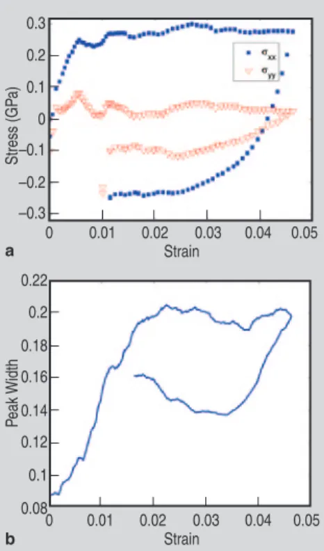
stress components in loading and trans-verse directions of the thin gold film is plotted versus the total strain in Figure 1a. The macroscopic yield stress of the gold film of 250 MPa is reached at a strain of 0.6% as seen in Figure 1a. Af-ter an initial small load drop, the gold film starts to work harden. Note that only relative stresses and not residual stresses are determined from the rela-tive lattice strains. Residual stresses can also be in principle determined from the difference in the stress plateaus between loading and unloading cycles which in the present case is not significant as seen in Figure 1a.
The Laue microdiffraction patterns (1,600 diffraction frames for each strain step) collected during the in-situ micro-diffraction tensile experiment (Figure Aa) have been indexed using the XMAS code.27 Complete pole figures have been
constructed for each strain step from the indexed Laue microdiffraction patterns corresponding to an area of 40×40 mm over the polycrystalline ensemble. Figure 2 shows complete {111}, {100}, and {115} pole figures for two different strains, i.e. 0.6% and 2%. The
0.3 0.2 0.1 0 –0.1 –0.2 –0.3 0.22 0.2 0.18 0.16 0.14 0.12 0.1 0.08 0 0 0.01 0.01 0.02 0.02 Strain Strain Stress (GP a) Peak Width 0.03 0.03 0.04 0.04 0.05 0.05 a b
Figure 1. (a) Principle stress components in loading (sx) and transverse (sy)
directions of the thin gold film as a function of total strain determined from the relative principle lattice strains from the in-situ synchrotron tensile experiment conducted at beamline X04SA at the SLS. At a strain of 0.006 the macroscopic yield stress of 250 MPa is reached and the sample starts to work harden. (b) Evolution of the (111) peak width with applied uniaxial strain.
Figure 2. Pole figures constructed from 1,600 indexed Laue microdif-fraction patterns cor-responding to the total scanned area over the polycrystalline ensem-ble of 40×40 mm. The {100} pole figure shows the random in-plane orientation of the {100} planes corresponding to the {100} ring in the pole figure. A fraction of the grains is 115 out of plane oriented as seen by the central peak in the {115} pole figure. (c) The total coverage of (111) and (115) out of plane oriented grains up to 2% strain. The color code in the contours scales with the density of points. 90 15 13 11 9 7 5 87 84 81 78 75 0 0.2 0.8 1 Tensile Strain (%) Co ver age of 115 Or iented Gr ains (%) Co ver age of 111 Or iented Gr ains (%) 1.2 1.4 1.6 1.8 2 0.4 0.6 a b c
{111} pole figures show the (111) out of plane texture of the gold film while the {100} pole figures show a correspond-ing random in-plane orientation. The majority of grains are (111) out of plane oriented while the remaining fraction is (115) out of plane oriented as seen by the central peak in the {115} pole fig-ures. The total grain coverage of the (111) out of plane and (115) out of plane oriented grains was determined from the complete pole figures for each strain step. Figure 2c shows the total coverage of (111) and (115) out of plane oriented grains up to 2% strain. The decrease in the grain coverage of the (111) oriented grains is accompanied by an increase in the grain coverage of the (115) oriented grains. The increase in the fraction of the secondary texture component up to 2% strain is also consistent with the texturing effect observed on the mac-roscopic scale using a monochromatic synchrotron x-ray beam during the in-situ tensile experiment on the same batch of samples at the MS beamline (X04SA). Figure 1b shows the continu-ous increase in peak width of the (111) peak which accompanies the continuous decrease in the total area under the (111) diffraction peak between 0.6 and 2% strain (decrease by approximately 40%) as determined by numerically integrat-ing the diffracted intensity of the (111) peak with respect to 2q.
Figure 3 shows contour plots of the smallest angle between the surface nor-mal and the <115> directions over a selected area of the polycrystalline en-semble for two different strain states. The grains have been identified by con-structing pole figures over the selected grain areas (Figure 3). The figure shows the {111} pole figures of the (111) ori-ented grains (grains numbered from 1 to 4) corresponding to the two different strain states. The (115) oriented grains have been identified in the same way and numbered in Figure 3 demonstrat-ing that a new (115) oriented deforma-tion twin has developed between two of the (111) oriented grains (between grains 1 and 4).
Subgrain Structure Rotations in Polycrystalline Thin Silver Films
The Laue microdiffraction patterns were indexed using the XMAS soft-ware package27,28 which allows indexing
Figure 3. Contour plots of the smallest angle between the surface film normal and the <115> crystallographic direction over a selected area of the polycrystalline ensemble for two different strain states. The pole figures below show the crystallographic orientations of the four (111)-oriented grains numbered from 1 to 4 in the contour plots for the two different strain states. At 0.06% strain the contour plot shows a new (115) deformation twin between the (111)-oriented grains (between grain 1 and grain 4). The transformation of Burgers vectors and lattice planes between deformation twin and matrix is discussed in the text.
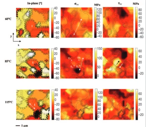
Figure 4. Contour maps of the in-plane orientation (smallest angle between the <100> crystallographic axis and the reference x-axis) as well as normal and shear deviatoric stress components. The grain of interest within the polycrystalline ensemble is numbered as 1. As the temperature increases from room temperature to 115°C, the grain is subject to a normal shear stress gradient, while a shear stress gradient develops within the grain at 85°C. As the temperature increases to 115°C a subgrain formation within the grain is observed corresponding to two misoriented crystal volumes of an in-plane misorientation of 1.4°. The crosses in the contour plot at 85°C (marked from T1 to T4) indicate the location
of the four triple junctions within the grain. 34 50 50 40 40 30 30 20 20 10 10 0 0 34 32 32 30 30 28 28 26 26 24 24 22 22 20 10 12 14 16 18 20 22 8 10 12 14 16 18 20 20 40 120 150 120 100 80 60 40 20 0 100 50 0 100 80 80 60 60 60 40 40 20 20 0 0 40 20 –20 –20 –20 –40 –60 0 60 40 20 –20 –40 0 40 40 20 20 20 0 0 0 –20 –20 –20 –40 –40 –40 –60 –60 –60 –80 –80 –80
overlapping Laue patterns originating from differently oriented grains. The crystallographic orientations have been determined from the absolute peak po-sitions, while the relative peak shift of the indexed peak positions allowed to determine the deviatoric strain tensor components with strain sensitivity of about 2∙10–4.
Following the evolution of both crystallographic orientations and the deviatoric stress state from room tem-perature to 150°C, we observe stress driven grain rotations and subgrain dis-location structure formations leading to plastic deformation heterogeneities. Figure 4 shows contour maps of both, the in-plane crystallographic orienta-tion and the deviatoric stress tensor components over the polycrystalline ensemble of interest for different ap-plied biaxial strain states (i.e., sample temperatures). Within the central grain (numbered as grain 1 in Figure 4) dis-located walls have formed as deter-mined by scanning the indexed Laue peaks across and along the misoriented crystalline domains. Scanning the in-dexed Laue peaks across the dislocated walls, the indexed peaks split into two discontinuous intensity maxima, while the peaks split into characteristic three peaks at triple lines where three misori-ented crystalline domains meet. As the temperature increases from 60°C to 85°C the crystal volume of the grain of interest (numbered as 1) rotates relative to the fixed sample reference
frame (as verified by tracking the ori-entation of silicon reference pattern) as shown by the evolution of the in-plane orientation along a profile through the grain (Figure 5). As the temperature in-creases to 85° the grain is subject to a shear stress gradient (corresponding to a shear stress difference of 100 MPa) and a stress gradient in the normal stress component as shown in Figure 4. Upon a further increase in applied bi-axial strain to 115°C a subgrain struc-ture forms within the grain as shown in the in-plane orientation contour in Figure 4. The in-plane misorientation between the corresponding crystalline domains of the subgrain is about 1.4° (Figure 5). The shear stress gradient within the grain relaxes upon the sub-structure formation as seen in Figure 4.
discussion
Conjugate Deformation Twinning in Polycrystalline Thin Au Films In this section the mechanism of the observed generation of deformation twins upon uniaxial strain deformation is discussed by analyzing the transfor-mations of the dislocation substructure from parent to twin for conjugate twin-ning. The theoretically expected trans-formations of the primary dislocations are determined and compared to the experimental results by analyzing the
streak patterns in the Laue microdif-fraction patterns. A specific dislocation mechanism, based on the pole mecha-nism, is discussed to describe the co-operative movement of the twinning dislocations generating the mesoscale deformation twins.
The crystallography of twinning is described by four independent twin-ning elements, two invariant undistort-ed planes (twinning plane and conju-gate twinning plane) and two directions (direction of the twinning shear strain and conjugate twinning direction).13,39
The twinning elements are identified by shearing a Thompson tetrahedron on successive (111) planes above the twin-ning plane by a partial Burgers vector (a/6 <112>). The conjugate twinning plane rotates to a different plane in the twin, while the twinning plane remains unchanged. For twinning of type I ac-cording to the classification of Bilby et al.,39 the transformation between the
crystallographic lattices and planes be-tween parent and twin is accomplished by a homogeneous shear deformation gradient. The reindexation matrix U specifies the transformation (rotation of p about the normal to the twin plane) between the crystallographic vectors in the parent to the ones in the twin ori-entation, while the correspondence matrix C describes the transformation of Burgers vectors from the parent to
–18.6 –18.8 –19 –19.2 –19.4 –19.6 –19.8 –20 –20.2 –20.4 0 0.25 0.5 0.75 1
Distance Along Profile [mm]
Angle Betw
een <100> and x-axis
1.25 1.5 1.75 2 Figure 5. In-plane crystallographic orien-tation plotted along a profile through the center of grain 1 for different tempera-tures. The plot shows the misorientation angles between the two misoriented crystalline volumes (1.4°) within the grain at a temperature of 115°C. Prior to the subgrain formation the crystal vol-ume of the grain rotates between 60°C and 85°C (mean in-plane rotation of 0.13°).
a b c
e d
Figure 6. (a–c) Schematic illustrating the transformation of the primary mobile a/2[101]T
dis-location and the twinning Shockley disdis-location a/6[121]T to the sessile a/6[424]T dislocation
(with reference to the matrix or parent coordinate system). When reindexed using the rein-dexation matrix U, the sessile a/6[424]T dislocation corresponds to the a/2[0-20]T dislocation
with respect to the twin coordinate system. (d) Laue streak simulation to the microdiffraction patterns of (111) oriented parent, and (e) (115) oriented deformation twin.
Table I. Misorientation Angles Corresponding to the Transformation Paths in Figure 7a Transformations A B C D K H DCBA 60°C +1.14 –0.78 +0.98 –0.60 +1.09 –1.10 0.74 Rotation angle (°) 85°C 0.69 –0.36 +1.25 –0.68 +1.00 –0.95 0.90 Rotation angle (°)
mobile a/2 [101]T dislocation is
di-rectly transformed to the sessile a/2 [010]T dislocation in the twin reference
frame according to the transformation shown in Equations 4 and 5.
Note that the transformations lead-ing to the generation of the conjugate twin extend over two nodes as illus-trated in Figure 6b. To investigate the twinning mechanism, the transforma-tion of Burgers vectors between defor-mation twin and parent lattice is exam-ined from the streaking of the indexed peaks in the Laue microdiffraction patterns between the (115) oriented de-formation twins and the (111) oriented parent lattice in Figure 3. The streak-ing of the Laue microdiffraction peaks has been simulated by introducing geometrically necessary dislocations (GNDs) on the primary <110>(111) slip system and tracking the corre-sponding cooperative movement of the Laue peaks for each of the 12 possible slip systems using the XMAS software package.27,28 The simulated Laue streak
pattern is superimposed on the Laue diffraction patterns in Figure 6d cor-responding to the (111) oriented grain (grain 1) in Figure 3. The slip sys-tem representing the best fit between simulated and measured streaks is
obtained for the Burgers vector bm = [101 ]T and slip plane normal n
m =
[ 111]T. The Laue microdiffraction
pattern of the (115) oriented deforma-tion twin (grain 7) is shown in Figure 6e. Laue streak simulations have been performed for the <111>(110), the <110>(001) as well as the <010>(100) system. The best fit to the experimen-tal Laue streak pattern was obtained for the Burgers vector bt = [ 010 ]T and
plane normal nt = [100 ]T and is shown
in Figure 6e. The transformations of Burgers vectors and lattice planes as demonstrated in the experimental Laue patterns is consistent with the trans-formation for conjugate detrans-formation twinning as specified by the correspon-dence matrix C (see Equation 6). The pole mechanism, first proposed by Cottrell and Bilby,41 provides an
elegant dislocation mechanism for the growth of the conjugate twin starting with one layer of a stacking fault. The primary a/2 [101]T dislocation
(com-pare to Figure 6a) is first dissociated into two Shockley partials thereby dis-torting the twinning plane in a helical topology. The intersecting twinning dislocations (a/6 [121]T) wind around
the dissociated primary dislocation (pole dislocation) generating a
mono-Figure 7. Representation of the system of closed dislo-cated walls in terms of par-tial wedge disclination mul-tipoles (b). Transformation paths (in red) around the disclination multipoles (a). The arrows indicate the di-rectional sense of the trans-formations of a vector as the dislocation wall is crossed and the bold letters the cor-responding transformation matrices. The product of transformations correspond-ing to a transformation path around the branching dislo-cation walls (DCBA) is equal to the rotational closure fail-ure corresponding to a Burg-ers circuit around contour C.
Equations 1 2 2 1 U 2 1 2 3 2 2 1 (1) 1 1 1 1 C 2 0 2 2 1 1 1 (2) T T U(111) (15 1) (3) T T T a a a [101] [121] [424] 2 6 6 (4) T T a U [424] a[0 10] 6 (5) bt = C bm (6) (7) Yi = Aijxj (8) A A A A cos( ) sin( ) 0 A sin( ) cos( ) 0 0 0 1 (9)
the twinned lattice including the shear deformation.13,40 (See Equations 1 and
2; all equations are shown in the table.) Using the reindexation matrix U, the crystallographic orientation of the con-jugate twins corresponding to a (111) orientation of the parent lattice is the (115) orientation in the twinned lattice, consistent with the secondary (115) texture in Figure 2 (see Equation 3). (In the notation used, column vectors are denoted as the transpose of row vectors using the superscipt T. The Einstein summation convention of a repeated index being summed is used throug-hout the paper.)
In Figure 6a–c, the transformation of a primary dislocation a/2 [101]T
with the partial twinning dislocation a/6 [121]T to a sessile a/6 [ 424 ]T
dis-location is illustrated in the reference frame of the parent crystal. The sessile a/6 [ 424 ]T dislocation corresponds to
the a/2 [ 010]T sessile dislocation (on
the (100) plane) when reindexed (us-ing the reindexation matrix U) to the twin reference frame. Using the cor-respondence matrix C, the primary
a b
Ω = kj
Ú
ijdxi Clayer of stacking fault after each spi-ral turn. In the present case, the thin film geometry is expected to enhance the driving force for such mechanisms as (i) dissociation of perfect disloca-tions is in general favored due to the size effect in thin film geometries, (ii) cross-slip and climb force components are enhanced due to image forces, (iii) pinning points for the pole dislocation may be provided at the substrate-film interface and the free surface of the film.
Subgrain Structure Rotations as a Manifestation of Changes in Burgers Vector Content
To understand the mesoscale rota-tional deformation of the grain, the plastic deformation heterogeneities comprising the system of branching dislocation walls (Figure 4) are ideal-ized by partial wedge disclination di-poles (Figure 7). Figure 7a illustrates the transformation paths across the branch-ing dislocated walls of the system of dislocation boundaries. The misori-entation angles for the corresponding transformation paths are summarized in Table I.
In analogy to the Burgers vector specifying the translational closure failure of a Burgers circuit around a dislocation line, the Frank vector specifies the rotational closure failure of a Burgers circuit around a disclina-tion line leading to rotadisclina-tional displace-ments of adjacent volumes of material. Any disclination may be represented by a superposition of dislocations, the simplest example is the wedge discli-nation dipole (in which the Frank vec-tor is parallel to the disclination line). For review on current state of the art and theory of disclinations reference is made to the work of Romanov and co-workers.18,19
Consider a Burgers circuit around the multipole disclination configura-tion as illustrated by the contour path C in Figure 7. The rotational closure fail-ure W for this contour path is specified by the closed loop integral of the local curvature tensor, as shown in Equa-tion 7, where k is the curvature ten-sor42 relating infinitesimal changes in
lattice rotations about an orthonormal vector basis (dxi) to the corresponding displacement field. For wedge
discli-nation dipoles, the Frank vector is in the boundary plane and parallel to the disclination lines such that the curva-ture tensor has only two non-vanishing components, i.e. k13 ≠ 0 and k23 ≠ 0. For
this case Equation 7 can be expressed in terms of the sum of the Frank vector strengths of the disclinations compris-ing the polygon of closed dislocation walls. The transformation matrix A specifies the transformation of a vector xj to yi as one of the dislocation walls is crossed, (Eqution 8), where the trans-formation matrix is specified by the corresponding misorientation angle qA
as Equation 9.
The rotational closure failure in Equation 7 is determined by the prod-uct of the transformation matrices cor-responding to a transformation path around the multipole disclination con-figuration (DCBA) in Figure 7a. The rotational closure failure correspond-ing to this closed path as determined from the measured misorientation an-gles is summarized in Table I. The ro-tational closure failure increases from 60°C to 85°C by 0.90°–0.74° = 0.16°. The rotation angle compares well with the in-plane rotation of the grain be-tween 60°C and 85°C (Figure 5). This result suggests that the rotational de-formation of the grain is a manifesta-tion of the change in the rotamanifesta-tional in-compatibilities comprising the coupled system of multifold branching dislo-cation walls. Note the analogy to the case of a translational closure failure in which the circulation (contour inte-gral) of the displacement gradient ten-sor determines the total Burgers vector. The analogous field quantities are the displacement gradient tensor and cur-vature tensor field k, Nye’s disloca-tion density tensor and the disclinadisloca-tion density, the total Frank vector W and the total Burgers vector. Any change in the local source terms (any Frank vector of the partial disclinations) de-termines the mechanical response of the coupled system (in the present case the structure rotation) comprising the system of dislocated walls. The ob-served mesoscale rotational deforma-tion of the grain is directly related to structural transformations of the dislo-cation substructure heterogeneity. Syn-chrotron experiments conducted at the SLS on polycrystalline thin gold films
revealed stress driven rotational plastic deformation mechanisms similar to the ones reported here.22 It is important to
note that in both studies, the thin films investigated comprised low stacking fault energy metals of different stack-ing fault energies, i.e. gold (55 mJm–2)43
and silver (17 mJm–2 )43 films. A partial
disclination dipole may be represented as a mesoscopic partial dislocation with an effective Burgers vector de-pendent on the length of the dipole arm and the Frank vector strength. Analo-gous to the partial dislocation border-ing a stackborder-ing fault for which the par-tial Burgers vector is not a translational symmetry operation, the Frank vector of a partial disclination is not a rota-tional symmetry operation.
conclusions
In-situ synchrotron diffraction ex-periments on polycrystalline thin gold films reveal the generation of conjugate deformation twins upon uniaxial defor-mation. Film stresses in the loading and perpendicular direction have been determined from the measured relative lattice strains yielding a macroscopic yield stress of about 250 MPa. The microdiffraction experiments demon-strate that the total coverage of grains in the secondary (115) twin orientation increases upon uniaxial strain deforma-tion at the expense of the total coverage of the (111) oriented grains. By ana-lyzing the streak patterns in the Laue microdiffraction frames between par-ent and deformation twin, the transfor-mation of Burgers vectors and lattice planes is demonstrated and shown to be consistent with the correspondence matrix for conjugate deformation twin-ning. The second plastic deformation mechanism investigated, comprised subgrain structure rotations upon bi-axial deformation in polycrystalline thin silver films. In the in-situ micro-diffraction experiments the sample was subjected to biaxial strains. The evolution of local strains and crystal-lographic orientations demonstrated a stress driven subgrain rotation leading eventually to a new subgrain structure. The observed rotational mechanical re-sponse is understood as the change in total Burgers vector content compris-ing the system of dislocated boundar-ies.
Ralph Spolenak is a TMS Member!
To read more about him, turn to page 9. To join TMS, visit www.tms.org/Society/Membership.aspx. acKnoWlEdGEmEnt
The kind support and discussions with beamline scientists Nobumichi Tamura and Martin Kunz from the Advanced Light Source are acknowl-edged. Also special thanks to Daniel Grolimund for his support during our beamtimes at the Swiss Light Source. references
1. W.D. Nix, Materials Transactions, 20A (1989), pp. 2217–2245.
2. D.-K. Kim et al., Thin Solid Films, 371 (2000), pp. 278–282.
3. F.Y. Genin and W.J. Siekhaus, J. Appl. Phys., 79 (1996), pp. 3560–3566.
4. B.C. Valek et al., J. Appl. Phys., 94 (2003), pp. 3757– 3761.
5. B.C. Valek et al., Appl. Phys. Lett., 81 (2002), pp. 4168-4170.
6. T. Li and Z. Suo, Int’l. J. Solids and Structures, 43 (2006), pp. 2351–2363.
7. S. Frank et al., Acta Materialia, 57 (2009), pp. 1442– 1453.
8. A. Seeger, Work Hardening (New York: Gordon & Breach, 1968).
9. A. Seeger et al., Philosophical Magazine, 2 (1957), pp. 323–350.
10. S.H. Oh et al., Acta Materialia, 55 (2007), pp. 5558– 5571.
11. G. Dehm et al., Acta Materialia, 55 (2007), pp. 6659–6665.
12. M. Chen et al., Science, 300 (2003), pp. 1275–1277.
13. J.W. Christian and S. Mahajan, Progress in Materials Science, 39 (1995), pp. 1–157.
14. D.A. Hughes et al., Scripta Materialia, 48 (2003), pp. 147–153.
15. D.A. Hughes et al., Acta Materialia, 45 (1997), pp. 105–112.
16. A. Godfrey and D.A. Hughes, Acta Materialia, 48 (2000), pp. 1897–1905.
17. A. Godfrey and D.A. Hughes, Scripta Materialia, 51 (2004), pp. 831–836.
18. A.E. Romanov and V.I. Vladimirov, Dislocations in Solids (Amsterdam: North Holland, 1992).
19. A.E. Romanov, European J. Mechanics - A/Solids, 22 (2003), pp. 727–741.
20. V.V. Rybin et al., Acta Metallurgica et Materialia, 41 (1993), pp. 2211–2217.
21. A.A. Zisman and V.V. Rybin, Acta Materialia, 44 (1996), pp. 403–407.
22. R.D. Nyilas et al., Acta Materialia, 57 (2009), pp. 3738–3753.
23. P. Müllner, Solid State Phenomena, 87 (2002), pp. 227–238.
24. P. Müllner and A.E. Romanov, Acta Materialia, 48 (2000), pp. 2323–2337.
25. P. Müllner et al., Acta Metallurgica et Materialia, 42 (1994), pp. 1727–1732.
26. P. Müllner, Scripta Metallurgica et Materialia, 33 (1995), pp. 1181–1186.
27. N. Tamura et al., J. Synchrotron Rad., 10 (2003), pp. 137–143.
28. N. Tamura et al., Materials Science and Engineering: A, 399 (2005), pp. 92–98.
29. R.I. Barabash et al., in: Encyclopedia of Materials: Science and Technology (Oxford, U.K.: Elsevier, 2001), p. 18.
30. R.I. Barabash et al., Matls. Sci. and Eng. A, 400-401 (2005), pp. 125–131.
31. R.I. Barabash et al., J. Appl. Phys., 93 (2003), pp.
5701–5706.
32. R.I. Barabash et al., J. Appl. Phys., 93 (2003), pp. 1457–1464.
33. R.I. Barabash and P. Klimanek, J. Appl. Crystallography, 32 (1999), pp. 1050–1059.
34. J. Böhm et al., Review of Scientifi c Instruments, 75 (2004), pp. 1110–1119.
35. B.D. Patterson et al., Nuclear Instruments and Methods in Physics Research Section A: Accelerators, Spectrometers, Detectors and Associated Equipment, 540 (2005), pp. 42–67.
36. S. Olliges et al., Acta Materialia, 55 (2007), pp. 5201–5210.
37. B. Schmitt et al., Nuclear Instruments and Methods in Physics Research Section A: Accelerators, Spectrometers, Detectors and Associated Equipment, 501 (2003), pp. 267–272.
38. B. Schmitt et al., Nuclear Instruments and Methods in Physics Research Section A: Accelerators, Spectrometers, Detectors and Associated Equipment, 518 (2004), pp. 436–439.
39. B.A. Bilby and A.G. Crocker, Proc. Royal Society of London. Series A, Mathematical and Physical Sciences, 288 (1965), pp. 240–255.
40. M. Niewczas, in: Dislocations in Solids; Volume 13, ed. F. Nabarro and J. Hirth (Dordrecht, The Netherlands: Elsevier, 2007), pp. 263–364.
41. A.H. Cottrell and B.A. Bilby, Philosophical Maganzine, 42 (1951), p. 573.
42. J.F. Nye, Acta Metallurgica, 1 (1953), pp. 153–162. 43. J.P. Hirth and J. Lothe, Theory of Dislocations (Columbus, OH: McGraw-Hill 1968).
Ralph D Nyilas, Stephan Frank, and Ralph Spo-lenak are with the Laboratory for Nanometallurgy, Department of Materials, ETH Zurich, Wolfgang-Pauli-Strasse 10, CH-8093 Zurich, Switzerland. Dr. Nyilas can be reached at [email protected].
![Figure 6. (a–c) Schematic illustrating the transformation of the primary mobile a/2[101] T dis- dis-location and the twinning Shockley disdis-location a/6[121] T to the sessile a/6[424] T dislocation (with reference to the matrix or parent coordinate s](https://thumb-eu.123doks.com/thumbv2/123doknet/14849882.629225/5.877.323.818.695.1004/schematic-illustrating-transformation-location-shockley-dislocation-reference-coordinate.webp)

