HAL Id: cea-02509262
https://hal-cea.archives-ouvertes.fr/cea-02509262
Submitted on 16 Mar 2020
HAL is a multi-disciplinary open access archive for the deposit and dissemination of sci-entific research documents, whether they are pub-lished or not. The documents may come from teaching and research institutions in France or abroad, or from public or private research centers.
L’archive ouverte pluridisciplinaire HAL, est destinée au dépôt et à la diffusion de documents scientifiques de niveau recherche, publiés ou non, émanant des établissements d’enseignement et de recherche français ou étrangers, des laboratoires publics ou privés.
3d thermo-chemical-mechanical simulation of power
ramps with alcyone fuel code
B. Baurens, J. Sercombe, C. Riglet-Martial, L. Desgranges, L. Trotignon, P.
Maugis
To cite this version:
B. Baurens, J. Sercombe, C. Riglet-Martial, L. Desgranges, L. Trotignon, et al.. 3d thermo-chemical-mechanical simulation of power ramps with alcyone fuel code. Top Fuel 2015, Sep 2015, Zurich, Switzerland. �cea-02509262�
1
3D THERMO-CHEMICAL-MECHANICAL SIMULATION OF POWER RAMPS
WITH ALCYONE FUEL CODE
B. BAURENS, J. SERCOMBE, C. RIGLET-MARTIAL, L. DESGRANGES,
CEA, DEN, DEC/SESCF-13108 Saint-Paul-lez-Durance, France.
L. TROTIGNON
CEA, DEN, DTN/STRI,
F-13108 Saint-Paul-lez-Durance, France.
P. MAUGIS
IM2NP, Aix-Marseille University, UMR CNRS 7334, 13397 Marseille, France.
ABSTRACT
This paper presents the coupling of the fuel performance code ALCYONE with the thermochemical code ANGE and its application to Iodine- Stress Corrosion Cracking (I-SCC). The coupling is illustrated by a 3D simulation of a power ramp. The release of chemically active gases (CsI(g), Tex(1<x<7)(g), TeI2(g), I(g), I2(g)…) is studied. The calculated radial distributions of iodine, caesium, tellurium and inert fission gas in the pellet fragment before and after the power ramp are successfully compared to Secondary Ion Mass Spectrometry (SIMS) measurements. Based on the 3D simulation, the definition of a stress corrosion initiation criterion is discussed.
1. Introduction
Fuel failures due to Iodine induced Stress Corrosion Cracking during Pellet-Cladding Interaction (PCI-SCC), as discovered in the early 1970’s [1], can be avoided in Light Water Reactors (LWR) thanks to optimized plant operational procedures and fuel management schemes. However, research and development programs are still undertaken worldwide in order to improve the understanding of the mechanisms possibly leading to PCI-SCC failures and to develop fuel cladding that can remain defect free at high Linear Heat Rates [2] (LHR).
The assessment of the PCI-SCC resistance of fuel rods prior or during irradiation often relies on thermo-mechanical calculations performed with fuel performance codes. In this respect, ALCYONE is the multi-dimensional fuel code for French Pressurized Water Reactors (PWR) rods co-developed by EDF, AREVA and CEA in the PLEIADES environment [3]. In the past decade, sophisticated models have been implemented in ALCYONE for the thermal and mechanical behaviour of the rods, including inert fission gas release and swelling. The chemical modelling of the fuel, however, has remained rather crude.
This paper presents results obtained from the incorporation of the chemical solver ANGE in the fuel code ALCYONE [4]. A 3D simulation of a ramp test performed on a UO2/Zircaloy-4 rod is then analyzed in details and the results compared to radial profiles
of xenon, caesium, iodine and tellurium from SIMS measurements performed before and after the power ramp. Finally, the definition of a PCI-SCC initiation criterion is discussed.
1. The fuel code ALCYONE
ALCYONE is a multi-dimensional fuel code which consists of three different schemes [5]: 1) the 1.5D scheme models the complete fuel rod discretized in axial segments, the fuel and cladding of each segment being further divided in annular rings, 2) the 3D scheme models the behaviour of one quarter of a pellet fragment with the overlying cladding, see
2 Figure 1, 3) the 2D(r,) scheme models the mid-pellet plane of a pellet fragment. The different schemes use the same Finite Element (FE) code CAST3M [6] to solve the thermo-mechanical problem and share the same physical material models at each node or integration points of the FE mesh. This makes the comparison of simulated results from one scheme to another possible with no dependency on the constitutive models. A detailed description of the main models and material parameters considered in the thermo-mechanical code ALCYONE can be found in [3] and [7]. The representation of the fragmented fuel pellet in the 3D scheme of ALCYONE is illustrated in Figure 1.
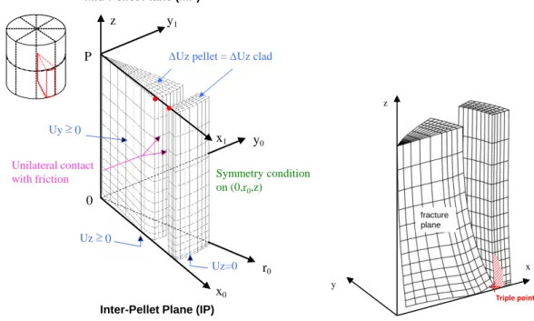
Figure 1 : Mesh and mechanical boundary conditions in the 3D scheme of ALCYONE (left). Illustration of the calculated pellet thermal hourglassing with the location of the so-called triple point (right).
Because of the geometrical symmetries, only one quarter of a pellet fragment and of the overlying piece of cladding are meshed. The mechanical boundary conditions considered in the 3D calculations are shown in Figure 1. To model thermal hourglassing, the pellet fragment is free to move upwards (Uz ≥ 0 at the inter-pellet plane 0x0y0) and away from
the central axis (0z). The opening and closing of the radial cracks between the pellet fragments is allowed by applying a unilateral condition (Uy ≥ 0) on the nodes of the 0x0z
plane. A locking condition (Uz pellet - Uz clad is kept constant) is used to forbid axial pellet
clad sliding when the gap is closed at least at one point. With such conditions, the 3D model is able to catch the stress-strain concentration at the so-called triple point [8] (axial location: Inter-Pellet plane, circumferential location: in front of a radial crack, radial location: inner clad wall), see Figure 1, where PCI-SCC clad failures usually occur during ramp tests.
2. The inert fission gas model MARGARET
MARGARET is a mechanistic model integrated in the fuel code ALCYONE to describe the behavior of the inert gases, xenon and krypton (referred to as xenon only or inert fission gas in the paper) generated by fission of uranium or plutonium in the fuel during in-reactor irradiations or power ramps. The model is called at each time step and at each node of the mesh, leading inert fission gas swelling strains and inert fission gas release estimates. MARGARET is not a macroscopic model in the sense that there are no connections between the calculations performed at different nodes. It is a local model that describes the behavior of inert fission gas at the grain scale. A detailed account of the equations and variables associated to the construction of the model can be found in reference [9].
x0 y0 z 0 Uz pellet = Uz clad y1 x1 P Uz=0 0 Uz 0 Uy r0 Symmetry condition on (0,r0,z) Unilateral contact with friction Mid-Pellet Plane (MP)
Inter-Pellet Plane (IP)
x y z
+
fracture plane Triple point3
3. The thermochemical code ANGE
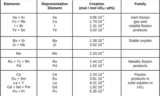
To determine the chemical states of the various Fission Product (FP) elements, the modeling calculations were carried out using the computation code ANGE (AdvaNced Gibbs Energy), new acronym for the former SAGE (Solgasmix Advanced Gibbs Energy) code, which was co-developed by CEA and EDF in the early nineties [10]. The ANGE software uses the Gibbs energy minimizing routines of the SOLGASMIX code [11] to calculate the equilibrium state of a multiphase and multicomponent system by minimising the total Gibbs energy at given temperature and pressure. Calculations for irradiated fuels require comprehensive thermodynamic data for all the compounds which are likely to be formed, both in the gaseous state and in the solid state (nonfluorite oxide phase, solid-solution compounds, metallic phases) [12]. The model describing the solid solid-solution of uranium, plutonium and dissolved fission products (trivalent rare earth mainly) is essentially based on the associated coumpounds description of Lindemer and Besmann [13], applied to the most abundant soluble fission products (Nd, Gd, Ce, La, Zr…) in UO2,
as described in reference [10] and [14]. The various phases and species considered are briefly discussed below and summarized in Table 1:
- The gas phase includes 61 species with as main components, Xe(g), Cs(g), Cs2(g), CsI(g),
Cs2I2(g), I(g), I2(g), Te(g), Te2(g), Te3(g), Te5(g), TeI2(g), Cs2MoO4(g). Special attention was given
to tellurium, for which major experimental results were obtained recently in our group [15], evincing the occurrence of gaseous tellurium-iodine compounds in power-ramped UO2
fuel rods.
- Stoichiometric separate phases are described by 72 species among which the liquid and solid phases of molybdates and zirconates, MoO2(s), MoO3(s), Cs2MoO4(s,l), CsI(l,s), Te(l,s),
Cs(l,s), Cs2Te(l,s), BaZrO3(s), ZrO2(s), Cs2ZrO3(s), Cs2UO4(s), BaTe(s).
- The fluorite oxide solid solution contains 23 dissolved species, including specific additions for Cs (Cs2O, Cs2O2, CsO2), Ba (and Sr), Zr and Eu oxydes coming from reference [14].
- Noble metal products are grouped into 3 species [14] and include Mo(s), Ru(s) (for
Ru+Tc+Rh) and Pd(s).
Elements Representative Element
Creation (mol / mol UO2 / at%)
Family Xe + Kr Cs + Rb I + Br Te + Se Xe Cs I Te 3.06 10-3 1.70 10-3 1.31 10-4 3.02 10-4 Inert fission gas and volatile fission products Ba + Sr Zr + Nb Ba Zr 1.38 10-3 2.62 10-3 Stable oxydes Mo Mo 2.33 10-3 Ru + Tc + Rh Pd Ru Pd 2.44 10-3 1.02 10-3 Metallic fission products Ce Eu + Sm La + Y Gd + Nd + Pm Pu + Pr Ce Eu La Gd Pu 1.24 10-3 3.81 10-4 9.31 10-4 1.92 10-3 5.35 10-3 Fission products in solid solution in UO2
Table 1: Quantities of fission product per at% burn-up and per mol of unirradiated UO2 fuel obtained from
CESAR calculations.
The estimation of the quantities of FPs in the fuel is based on calculations performed with the depletion code CESAR [16], which provides estimates of the depletion, decay and transmutation of up to 200 isotopes. Typical PWR irradiation histories on UO2-Zy4 fuel
rods have been used in CESAR in order to determine a set of empirical correlations giving the amount of FPs (expressed in mol/mol of initial UO2) as a function of burn-up
4 of interest. To simplify the thermochemical analyses and to compensate the lack of some specific thermochemical data, the number of FPs calculated by CESAR has been reduced and grouped in 14 “chemical” elements with similar physico-chemical behavior [10][14] as summarized in Table 1. The quantities are given 3 months after the end of base irradiation which means that most of the short lived radioactive isotopes have disappeared. Fregonese and al. [18] showed in their calculations of stable and radioactive iodine isotopes atoms created during a typical PWR 2 cycles base irradiation and ramp sequence that the quantity of radioactive isotopes was negligible compared to the stable part. Therefore, the 129I and 127I isotopes only are considered for iodine in Table 1.
4. Thermo-chemical-mechanical calculation scheme
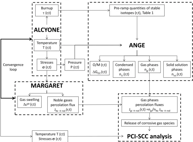
The incorporation of the thermochemical solver ANGE in the convergence loop of the thermo-mechanical code ALCYONE and of its inert fission gas release model MARGARET is illustrated schematically in Figure 2. The connection between ALCYONE thermo-mechanical outputs and the solver ANGE is straightforward. Basically, at each node of the mesh and at each time step, the burn-up , the temperature T and the hydrostatic pressure P (from the stresses ) are obtained from ALCYONE calculations and are used as input data for ANGE. The estimation of the quantities of FPs (per mol of unirradiated UO2) at each node is based on the burn-up dependent empirical relations
given in Table 1. In return, ANGE provides at each node estimates of the concentrations in the main solid, liquid, gaseous and dissolved phases in the fuel together with the resulting oxygen potential GO2 and Oxygen/Metal ratio (O/M).
Figure 2: Schematic representation of the coupling between the thermo-mechanical fuel code ALCYONE, the inert fission gas model MARGARET and the thermo-chemical code ANGE.
The question of how chemically-active fission gas move in the fuel and of how they are released to the gap is not a simple one. In this work, the following approach was therefore adopted to couple the thermo-mechanical code ALCYONE with the chemical component ANGE and the inert fission gas release model MARGARET. As illustrated in Figure 2, at
Noble gases percolation flux JXe → rod(r,t) Burnup (r,t)
ALCYONE
MARGARET
ANGE
Gas phases ngi(r,t)Release of corrosive gas species Condensed phases nci(r,t)
PCI-SCC analysis
O/M (r,t) GO2 (r,t)Pre-ramp quantities of stable isotopes (r,t), Table 1 Temperature T (r,t) Stresses (r,t) Stresses (r,t) Temperature T (r,t) Pressure P (r,t) Gas swelling gs(r,t) Solid solution phases nssi(r,t) Gas phases percolation fluxes Jgi → rod(r,t) =ngi/nXeJXe → rod Convergence loop
5 each time step of a typical loading sequence, ANGE provides the spatial distribution of the concentrations in gas species, condensed phases and of the phases dissolved in the U-Pu-O solid solution. It is then assumed that only the gas species that have formed can be released from the fuel. Condensed phases in the fuel are assumed immobile. Ideal binary mixtures of each gas species with the major gas phase, i.e., xenon, are then considered to define the transport of the minor components. The molar flux of each gas species i to the rod free volume (𝐽𝑔𝑎𝑠(𝑖) →𝑟𝑜𝑑) is obtained from the inert fission gas flux to the fuel rod (𝐽𝑋𝑒 →𝑟𝑜𝑑) given by MARGARET and from the proportion of the gas species i (ni) in the
interconnected bubbles/pores filled with xenon (nXe).
5. 3D simulation of a high-temperature ramp test
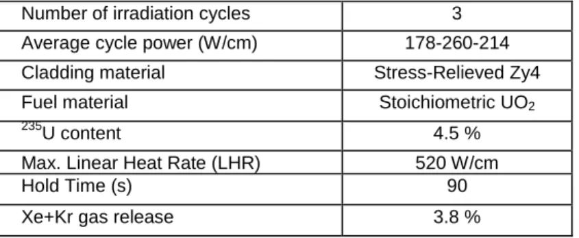
A 3D simulation of the short holding time ramp studied in reference [15] was performed to assess the validity of the coupling scheme. The main characteristics of this ramp are described in Table 2. This power ramp is interesting for PCI-SCC studies because of the high power reached (max. LHR of 520 W/cm) which led to the development of I-SCC cracks on the inner surface of the cladding with a maximum penetration of around 100 µm. The short hold time (90 s) did not permit the extension of the cracks across the full thickness of the cladding thus leading to a rare case of ramp test with PCI-SCC initiation but no failure.
Number of irradiation cycles 3
Average cycle power (W/cm) 178-260-214
Cladding material Stress-Relieved Zy4
Fuel material Stoichiometric UO2
235
U content 4.5 %
Max. Linear Heat Rate (LHR) 520 W/cm
Hold Time (s) 90
Xe+Kr gas release 3.8 %
Table 2: Main characteristics of the simulated Short Hold Time power ramp.
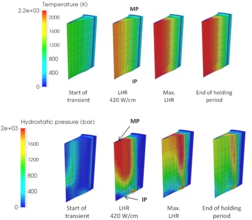
5.1. Temperature and Hydrostatic Pressure
Figure 3 shows the calculated evolution of the temperature and hydrostatic pressure inside the fuel pellet fragment at different times during the power ramp. The respective positions of the Mid- and Inter-Pellet planes are indicated (with acronyms MP and IP). The four times of interest are: the end of the conditioning period (start of transient), when two thirds of the power transient are accomplished (LHR 420 W/cm), the end of the power transient (max. LHR), the end of the holding period (after 90 s at the max. LHR).
The increase of LHR during the power ramp leads to the establishment of a parabolic radial temperature profile in the pellet fragment. A maximum central temperature of 2400 K is obtained at the end of the transient while the periphery of the pellet remains at approximately 700 K. A thermal gradient in a cylindrical pellet with no dishes and in contact with a cladding bore leads theoretically to a stress distribution where the central hot part of the pellet is under tri-axial compression and the pellet periphery is in biaxial tension. During the power transient, the thermal gradient increases leading in the central part of the pellet and far from pellet ends to high hydrostatic pressures. As can be seen in Figure 3, when the LHR reaches 420 W/cm, the pressure calculated at MP level reaches 2000 bars, see the red zone at the top of the fragment. On the contrary, the hydrostatic pressure in the central part of pellet ends (IP level, bottom of the fragment) is very close to the rod internal pressure, 70 bars, see the blue zone near the dish. The dish has in fact a strong impact on the stress field since it tends to release the axial and hoop stresses. In consequence, a strong axial stress gradient takes place in the pellet fragment during the power transient.
6
Figure 3: Calculated evolution of the temperature (K) and hydrostatic pressure (bars) in the fuel fragment during the power ramp.
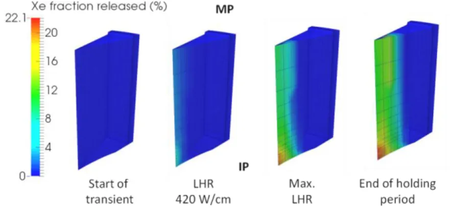
5.2. Inert fission gas release
The calculated fraction of inert fission gas released from the pellet fragment during the power ramp is given in Figure 4. In the MARGARET model, the average volume and number of inter-granular bubbles at the grain boundary surface depends greatly on the hydrostatic pressure. The lower the hydrostatic pressure, the greater the volume of the bubbles and the smaller their number. Because of their greater size compared to the limited grain boundary surface available, large bubbles tend to interconnect more easily and then form more easily accessible channels to the grain edges. The latter is the necessary condition for gas release in the free volume of the rod. Due to the very important axial hydrostatic pressure gradient in the central part of the pellet, the release of inert fission gas at the IP plane is approximately equal to twice that calculated at the MP plane when the maximum LHR is reached: 20% at IP level compared to 12% at MP level, see Figure 4. The IP plane where the hydrostatic pressure is the lowest releases the most.
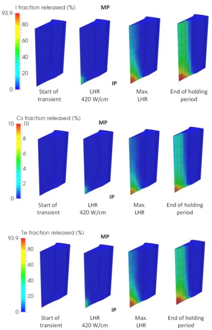
5.3. Volatile FP release
The calculated fraction of iodine, caesium and tellurium released from the pellet fragment during the power ramp are shown in Figure 5. Since the volatile fission product release during the power transient and the holding period is related to the inert fission gas percolation flux, the iodine, caesium and tellurium release from the pellet is also more pronounced near the IP plane. The axial gradient of species release at the pellet center is, however, much more pronounced than for xenon. At the maximum LHR, iodine and tellurium release from the pellet center exceed 90% close to the dish for approximately 30% at MP level. This result stems from a major impact of thermo-mechanics on thermochemistry. In fact, at MP level, the high hydrostatic pressure (>2000 bars) applied on the oxide matrix reduces the formation of gas species (other than inert gases) to the benefit of liquid or solid species. Conversely, at the IP level, the hydrostatic pressure is much lower ( 70 bars) which favors the formation of gaseous compounds, and the xenon
7 flux is much higher. Consequently, we calculate local releases of iodine and tellurium at the IP level three times higher than at the MP level.
Figure 4: Calculated evolution of the inert fission gas release (%) in the fuel fragment during the power ramp.
6. Comparison of fission product concentrations to SIMS measurements
The radial distribution of fission products were measured before and after the ramp test by means of SIMS in a pellet close to the PPN [14]. The methodology is described elsewhere [19].
To obtain experimental data comparable to simulation results at the end of the power ramp, the following procedure was adopted for each fuel element. First, the SIMS profiles obtained before ramp are used to determine base lines representative of the pre-ramp distribution. The SIMS profiles after ramp are then divided by the base lines to get the ratio of the quantity of the element remaining in the pellet over the creation (assuming that negligible release took place during base irradiation). This estimation is furthermore based on the hypothesis that negligible quantities of stable isotopes are formed during the power ramp and the short holding period. These experimental radial profiles are compared in Figure 6 to the calculated ratios of the quantity of element remaining in the pellet at the end of the ramp over the initial quantity (the profiles are extracted from the MP plane of the pellet fragment, see the red line on the pellet fragment mesh).
Overall, the simulations lead to radial profiles in good agreement with the SIMS measurements. The important depletion of iodine and tellurium at the pellet center is well reproduced. It reaches locally more than 60% of the total quantity for both elements to be compared with the 15% xenon and 5% caesium released at the pellet center. The xenon radial profile is slightly underestimated near the pellet center, which is consistent with the overall underestimation of the inert fission gas release from the pellet fragment (2.7% calculated for 3.8% measured in the fuel rodlet). The higher fraction of iodine and tellurium released is due to the combination of the high temperature at the pellet center that triggers the formation of a majority of gaseous compounds, with the hypothesis of a chemical equilibrium determined at the grain boundaries that ensures a fast release from the fuel. The important difference between the iodine – tellurium and the caesium radial profiles is well captured by the simulation and is a consequence of the low caesium fraction available in gaseous compounds.
7. Definition of a PCI-SCC initiation criterion
The occurrence of PCI-SCC in a ramp test depends on three main factors [1] : a sufficient stress in the cladding, a release from the pellet of a sufficient quantity of corrosive gases, the presence of a corrosive chemical environment at the clad inner surface.
8
Figure 5: Calculated evolution of the fraction of iodine, caesium and tellurium released (%) in the fuel fragment during the power ramp.
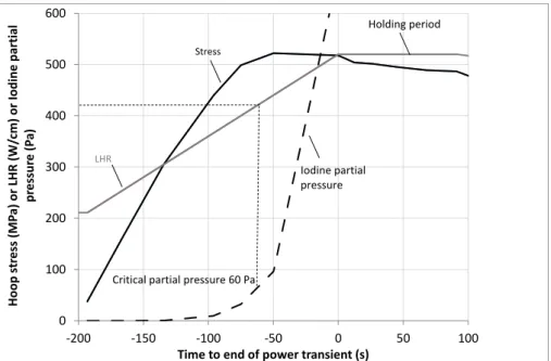
Figure 7 gives the evolution during the ramp of the calculated clad hoop stress at the exact location of the triple point together with the LHR and the dish filling. Time 0 refers to the end of the power transient (or beginning of the holding period). A maximum stress exceeding 500 MPa is reached at IP level approximately 50 seconds before the end of the transient and maintained quasi-constant afterwards.
Our simulations identify four main compounds containing iodine that are released from the pellet: CsI(g), TeI2(g), I(g) and I2(g) with CsI(g) as the most abundant gas species (96%) and a
90-10% proportion of TeI2(g) and I(g)+I2(g). The Gibbs energies of the potential reactions of
I(g), I2(g), CsI(g) and TeI2(g) with zirconium (from the ANGE database) show that the
formation of ZrI4(g) from CsI(g) is not likely to take place. On the contrary, the formation of
ZrI4(g) from I(g) and I2(g) is possible at all temperatures. The reaction between TeI2(g) and
zirconium is likely to occur only at temperatures less than 900 K. The chemical conditions for I-SCC initiation can therefore be assessed by plotting the evolution of the partial pressure of “reactive iodine” from the TeI2(g), I2(g) and I(g) released by the pellet. The free
volume used to obtain the iodine partial pressure is estimated at each time step from the remaining volume of the pellet dish, the radial crack opening and the plenum volume of
9 the rod divided by the number of pellet fragments in the rodlet. From mandrel testing of irradiated zircaloy-2 tubes at 350°C in an anoxic atmosphere, Anghel and al. recently showed the existence of a reduced I-SCC susceptibility below 60 Pa of iodine partial pressure [20]. The 60 Pa iodine partial pressure is reached at time -60 s when the hoop stress is maximum and increases tenfold at the end of the transient (time 0 s, PI > 600
Pa).
Figure 6 : Comparison between calculated and experimental radial profiles of xenon, caesium, iodine and tellurium (all FPs measured by SIMS) in the pellet at the end of the power ramp.
Figure 7: Calculated evolution of the maximum hoop stress at IP level (MPa) and of the “reactive iodine” total
pressure (Pa) during the power ramp. “Reactive iodine” includes the iodine species TeI2(g), I(g) and I2(g).
0 0.2 0.4 0.6 0.8 1 1.2 1.4 1.6 0 0.2 0.4 0.6 0.8 1 X enon r emaining in the fuel ov er cr ea tion Relative radius (r/R) Calculated SIMS 0.0 0.2 0.4 0.6 0.8 1.0 1.2 1.4 1.6 0 0.2 0.4 0.6 0.8 1 Cesium in so lid or liqu id st at e ov er cr ea tion in the fuel Relative radius (r/R) SIMS Calculated 0.0 0.2 0.4 0.6 0.8 1.0 1.2 1.4 1.6 0 0.2 0.4 0.6 0.8 1 Io d ine in s olid or liqu id st at e o ver cr ea tio n in the fu el Relative radius (r/R) SIMS Calculated MP IP 0.0 0.2 0.4 0.6 0.8 1.0 1.2 1.4 1.6 0 0.2 0.4 0.6 0.8 1 Tellur ium in solid or liquid st at e ov er cr ea tion in the fuel Relative radius (r/R) SIMS Calculated 0 100 200 300 400 500 600 -200 -150 -100 -50 0 50 100 Ho op s tr e ss ( MP a) o r LHR (W/ cm) or Io d in e p artial p re ssu re (P a)
Time to end of power transient (s)
Stress
Holding period
LHR
Iodine partial pressure
10 8. Conclusions
In this paper, the coupling of the multi-dimensional fuel performance code ALCYONE with the thermochemical code ANGE has been presented. A 3D thermo-chemical-mechanical simulation of pellet cladding interaction during a power ramp has shown that the release of chemically active gases (i.e. CsI(g), TeI2(g), I(g), I2(g) and Tex(g)) was enhanced near pellet
ends due to the combined effect of a higher inert fission gas flux and a lower hydrostatic pressure, which tends to increase the proportion of the gas phase in the fuel according to the calculated chemical equilibria. The calculated radial distribution of FPs in the fuel after the ramp test have been compared to SIMS measurements. The important difference in the iodine or tellurium distribution at the pellet center compared to that of caesium and inert fission gas was successfully obtained from the coupled simulation due to the impact of chemical equilibrium in the fuel grain boundaries on gas release. Finally, based on the 3D coupled simulation, the definition of a PCI-SCC initiation criterion has been discussed. The combination of the hoop stress at the triple point (in front of pellet ends) and of the amount of reactive iodine (from I(g), I2(g) and TeI2(g) only) released by the pellet was used to
show that the necessary conditions for PCI-SCC initiation were met before the end of the power transient.
Acknowledgements
The authors would like to thank AREVA and EDF for the financial and technical support to this work.
References
[1] B. Cox (1990). Journal of Nuclear Materials (172) 249-292.
[2] C. Delafoy et al. (2007). International LWR Fuel Performance Meeting, San Francisco. [3] B. Michel et al. (2012). Comprehensive Nuclear Materials., Elsevier.
[4] B. Baurens et al. (2014). Journal of Nuclear Materials (452) 578-594. [5] B. Michel et al. (2013). Nuclear Technology (182) 124-137.
[6] Cast3M, http://www-cast3m.cea.fr/, [Online].
[7] J. Sercombe et al. (2012). Nuclear Engineering and Design (242) 164-181. [8] J. Sercombe et al. (2013). TopFuel Conference, Charlotte, 2013.
[9] L. Noirot (2011). Journal of Nuclear Materials (241) 2099-2118.
[10] P. Garcia et al. (1994). Water reactor fuel element modelling at high burnup and its Experimental Support (IAEA), Windermere (UK).
[11] G. Eriksson (1975). Chem. Scripta (8) 100-103.
[12] B. J. Lewis et al. (2012). Comprehensive Nuclear Materials (2) 515-546. [13] T. M. Besmann (2012). Comprehensive Nuclear Materials (1) 455-470.
[14] J. Dumas (1995). PhD thesis, Institut National Polytechnique, Grenoble, France. [15] L. Desgranges et al. (2013). Journal of Nuclear Materials (437) 409-414.
[16] J.-M. Vidal et al. (2012).Waste Management 2012, Phoenix, Arizona, USA. [17] N. N. Greenwood and A. Earnshaw (1998). Chemistry of the elements, Second edition, Butterworth-Heinemann.
[18] M. Fregonese et al. (1998). Journal of Nuclear Materials (186) 307-322.
[19] L. Desgranges et al. (2008). Nuclear Instruments and Methods in Physics Research (266) 147-154.