HAL Id: hal-01071304
https://hal-paris1.archives-ouvertes.fr/hal-01071304
Submitted on 6 Oct 2014
HAL is a multi-disciplinary open access
archive for the deposit and dissemination of
sci-entific research documents, whether they are
pub-lished or not. The documents may come from
teaching and research institutions in France or
abroad, or from public or private research centers.
L’archive ouverte pluridisciplinaire HAL, est
destinée au dépôt et à la diffusion de documents
scientifiques de niveau recherche, publiés ou non,
émanant des établissements d’enseignement et de
recherche français ou étrangers, des laboratoires
publics ou privés.
Capturing variability in Model Based Systems
Engineering
Cosmin Dumitrescu, Patrick Tessier, Camille Salinesi, Sébastien Gerard, Alain
Dauron, Raúl Mazo
To cite this version:
Cosmin Dumitrescu, Patrick Tessier, Camille Salinesi, Sébastien Gerard, Alain Dauron, et al..
Cap-turing variability in Model Based Systems Engineering. Complex Systems Design & Management
(CSD&M) Conference, Dec 2013, Paris, France. pp.100-115. �hal-01071304�
Engineering
∗
Cosmin Dumitrescu, Patrick Tessier, Camille Salinesi, Sebastien G´erard, Alain Dauron, and Raul Mazo
Abstract Automotive model-based systems engineering needs to be adapted to the industry specific needs, in particular by implementing appropriate means of rep-resenting and operating with variability. We rely on existing modeling techniques as an opportunity to provide a description of variability adapted to a systems en-gineering model. However, we also need to take into account requirements related to backwards compatibility with current practices, given the industry experience in mass customization. We propose to adopt the product line paradigm in model-based systems engineering by extending the orthogonal variability model, and adapting it to our specific needs. This brings us to an expression closer to a description of constraints, related to both orthogonal variability, and to SysML system models. We introduce our approach through a discussion on the different aspects that need to be covered for expressing variability in systems engineering. We explore these as-pects by observing an automotive case study, and relate them to a list of contextual requirements for variability management.
∗ Published in Complex Systems Design & Management, Paris, December 2013
Cosmin Dumitrescu · Alain Dauron RENAULT
1 Av. du Golf
78288 Guyancourt, France
e-mail: {cosmin.dumitrescu,alain.dauron}@renault.com Patrick Tessier · Sebastien G´erard
CEA, LIST
Laboratory of Model Driven Engineering for Embedded Systems Point courrier 174 F91191 Gif Sur Yvette, France
e-mail: {patrick.tessier,sebastien.gerard}@cea.fr Camille Salinesi · Cosmin Dumitrescu
Universit´e Paris I Panth´eon-Sorbonne 90 rue de Tolbiac, 75013 Paris, France
e-mail: {camille.salinesi,raul.mazo}@univ-paris1.fr
1 Introduction
Product diversity has an impact on all organization levels. However, one of the areas that could benefit and improve in respect to the management of variability in auto-motive, is model based systems engineering (MBSE). Our purpose is to introduce a variability modeling technique in MBSE, that would bridge the gap between vehicle features and component specifications, by introducing variability management on an intermediate level. This would enable engineers to design systems for reuse. For instance, reuse modules, components, and also specifications, requirements, or doc-umented system architectures. We aim to draw on the valuable experience provided by software product line engineering and either adopt or adapt modeling techniques for model based systems engineering context and existing product variety practices at Renault.
1.1 Motivating examples
The problem we are facing can be analyzed from multiple perspectives: from an information systems point of view (structure, storage, accessibility of data, compat-ibility with legacy systems), modeling techniques and extension of systems engi-neering meta-models, processes and specific practices. We need to adopt a research protocol which enables us to gradually refine our research problem in respect to each of these aspects, as explained in Section 4.
However, in order to provide some insight on the context and modeling issues, we present some simple variability modeling examples.
Issue 1: Need for flexibility and detail.The Constraint Satisfaction Problem (CSP) formalisms are suited for a great variety of problems. For instance, they can be used for product configurations, and the representation of the catalog or range of prod-ucts, at Renault [2]. This representation provides an efficient mean of interacting with customers through online configurators in order to create custom vehicle con-figurations.
For example, let’s consider the following boolean variables:
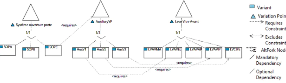
1. Door opening system: SOPA, SOPB, SOPC (three types of door opening sys-tems);
2. Window lifts: FMWL (front manual window lifts), EFWL (electric front window lifts), FAPWL (front anti-pinch window lifts), EIWL (electric impulse window lifts), FIDEP (front electric impulse for driver side and electric for passenger side);
and the constraint:
Constraint 1 imposes that variant SOPC of the vehicle door opening system requires the use of only one of the three variants of window lifts: ”electric front window lifts”, ”electric impulse front window lifts”, or ”front electric impulse for driver side and electric for passenger side window lifts”.
In the case of Renault, the CSP formalism, implemented through the organization ”documentary language”, captures characteristics of already developed products. This is why it is only possible to take into consideration some of these constraints only once the product is fully developed and the appropriate variables and con-straints were added to the lexicon (variables in the ”documentary language” express-ing vehicle characteristics). However, some of these constraints, as in the case of constraint 1, are technical by nature and are discovered only during system design. Furthermore, detailed requirements and design variability is not captured through the ”documentary language”, which would enable system engineers to apply con-figuration techniques for the reuse of requirements and specifications on any level of detail.
Renault’s product range is very broad, leading to 1021 possible configurations for the Traffic van product family [2]. On the one hand, further increasing the num-ber of variables, to capture more detailed variability for each vehicle system, would only create even more complex problems for online configurators. On the other hand, variability expression in MBSE needs to be compatible with legacy systems, although variability models could be local for each family of systems (vehicle sub-systems).
Issue 2: Representation of ”complex” constraints.One of the modeling techniques for variability, the orthogonal variability model (OVM), was introduced by Pohl et al. [16] to manage variability in the context of software product lines. The for-malism, presented in Figure 1, enables the representation of constraints such as ”re-quires” and ”excludes” between variants and variation points. To express constraints 1 using OVM, we need to introduce an auxiliary variation point - AuxiliaryVP - as shown in the diagram3from Figure 1.
Issue 3: Variability in system architectures.Another formalism for variability
mod-Fig. 1 Using an auxiliary variation point to express constraints using OVM notation
3 Diagram realized using the VARMOD Prime Tool
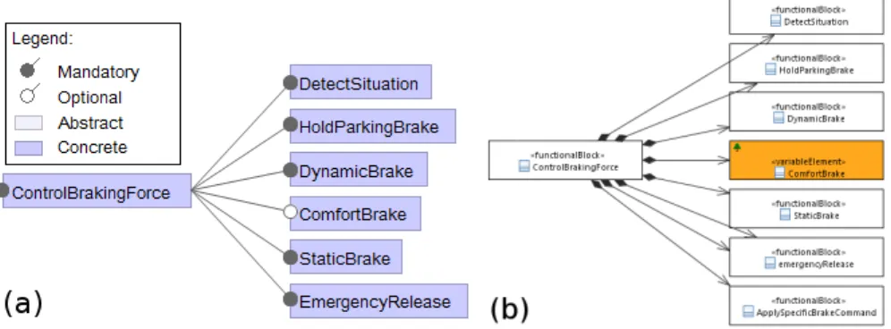
eling is the Feature Model (FM) [13]. FMs have become the most widely accepted modeling technique for variability management in the field of software product lines . FMs have the advantage of being easy to understand and independent of specific domains. Figure 2 presents two possible ways for modeling the functional decomposition for the electric parking brake system (EPB): (a) using the FM hier-archy to represent common and optional functions4and (b) applying the stereotype
<< variableElement >> [26] to distinguish common and optional functions in SysML(UML).
In the case of system architectures, hierarchies are already introduced through de-composition, such as the functional or physical structures, which means we can imagine two scenarios to make use of FMs. In the first case, a partial feature struc-ture may be deduced from variability in the system architecstruc-ture along with the con-straints imposed by the semantics of the SysML system model. However, character-istics defined in the ”documentary language” are not structured in the same hierar-chical way. In a second case, the system engineer would create hierarchies for both variability and architectures. However, this would result in redundant information and increase in the model complexity.
We propose in this article to adopt an extended orthogonal variability model
Co-Fig. 2 Electric Parking Brake system (partial) functional decomposition (a) using the FM notation; (b) using stereotyped ”optional” SysML block elements
OVM (Constraint Oriented Orthogonal Variability Model) to cover specific needs for systems engineering at Renault. Co-OVM is implemented as a UML profile in the SysML modeler Papyrus as an extension to Tessier’s Sequoia plug-in [26]. The article is structured in 7 parts. Following the introduction, we present in Section 2 an overview of existing variability modeling techniques. Section 3 develops the subject around different aspects that should be taken into account to introduce vari-ability management in our MBSE framework. Section 4 introduces the requirements for a variability management approach in the context of systems engineering at
Re-4 Diagram realized using FeatureIDE http://wwwiti.cs.uni-magdeburg.de/iti_
nault and the meta-model based on the identified concepts. Section 6 explains the implementation and results regarding MBSE variability management tools, based on the modeler Papyrus. Finally, Section 7 concludes the paper by some perspectives to our work.
2 Related work
Many variability modeling techniques exist [13][16][26][22]; however, the simple implementation of such an approach in a large organization would have some short-comings and challenges, as pointed out by Filho et al. [10]. They would have to be adapted to the specific context of the organization.
Variability models diverged into numerous dialects through extension, adaptation or through application in general purpose modeling languages.
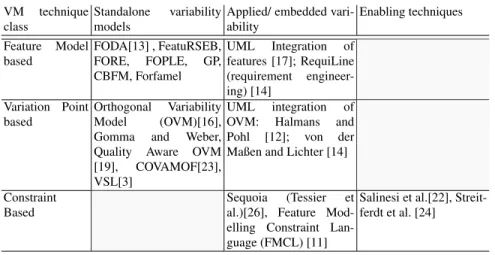
By drawing on comparisons and classifications [7][6][1][23] for an overview of variability modeling techniques, we propose the following synthesis: (a) distinct conceptual models for variability; (b) embedding variability in existing modeling languages or artifacts; and (c) realization techniques [23], enabling technologies (e.g., off-the-shelf solvers for constraints). A short summary presenting the classi-fication of these techniques is presented in table 1, which do not take into account aspect oriented modeling for variability, as we considered this to be a software spe-cific technique.
Our aim is to embed variability concepts in SysML models, while providing
VM technique class
Standalone variability models
Applied/ embedded vari-ability Enabling techniques Feature Model based FODA[13] , FeatuRSEB, FORE, FOPLE, GP, CBFM, Forfamel UML Integration of features [17]; RequiLine (requirement engineer-ing) [14] Variation Point based Orthogonal Variability Model (OVM)[16],
Gomma and Weber,
Quality Aware OVM [19], COVAMOF[23], VSL[3]
UML integration of
OVM: Halmans and
Pohl [12]; von der Maßen and Lichter [14]
Constraint Based
Sequoia (Tessier et al.)[26], Feature Mod-elling Constraint Lan-guage (FMCL) [11]
Salinesi et al.[22], Streit-ferdt et al. [24]
Table 1 Classification of variability modelling techniques
compatibility to the company ”documentary language” and support for our MBSE framework [5].
3 Identification of concepts for the representation of variability
in Systems Engineering
System models alone are not able to completely ensure traceability from require-ments to the implementation when variability is present. For example, variability traceability needs to be ensured in relation to the project or business context and system assets, answering to the questions: who specifies variability?, what is the rationale for increasing variety?, to which context does a particular expression of variability apply? Based on our industrial experience, we can claim that variability is present not only on the client offer level, but also on the solution level through design alternatives and replaceable components.
The system model needs to be complemented with relevant information for captur-ing variability. Several aspects are essential for the representation of variability in model based systems engineering, which shall be discussed in this section.
Types of variability. The central concept, implicit in all variability languages is the choice[15]. The act of performing choices can be regarded either as creating a configuration (e.g., online configurators) or as decision making, involving specific engineering domain information, with impact on the final derived system model. Indeed, approaches such as DOPLER [18] refer to choices as decisions, and the ”decision oriented” model represents a link between the domain of assets and the derived system. ”Features” capture high level variability in requirements, exposed to the customer (or stakeholders) and enable system configuration from a higher level of abstraction, without focus on decisional impact.
In respect to the design space, a decision oriented derivation would be directed from the problem to the solution space, whereas a non-decision oriented configurations would not take into account any particular workflow. To our opinion all these ap-proaches are useful at certain phases in the lifecycle of the system. We can thus identify: design decisions with impact on the system model, characteristics that con-tribute to products diversity and replaceable system parts (e.g., components from different suppliers, and COTS).
Sources of variability. Because existing vehicle level variants further impact the development each subsystem, it is important to trace their origin, where they first occur. For example, variations for the gear box (automatic or manual), indirectly re-quire the development of alternative behaviors for the electric parking brake (EPB) system. Since not all vehicle models propose both automatic and manual gearboxes, it is important to trace the origin of variability and the targeted configurations. The source may be one of the system levels of decomposition, abstraction level (operational scope, behavior, physical), technical context (enabling systems), envi-ronment (climate, country external conditions etc.), stakeholder viewpoints, or the ”documentary language”. When the system model does not provide sufficiently fine grained information for traceability, it is possible to add more detailed information in respect to the variation source, to point to specific model elements. Once intro-duced, the variation may further impact lower levels of abstraction. (e.g., functional variability may induce the same variations of a physical level). One interesting
as-pect of automotive systems is that there is much more physical variability in systems - related to alternative or shifting technologies, and component suppliers - rather than functional variability.
Legacy variability specification. Product variety is not a new concern in the au-tomotive industry. new. As systems engineering takes into account variability, both the tools and existing knowledge for mass customization need to remain compatible and provide a base for new MBSE tools.
The ”documentary language” enables the description of variability on the vehicle level. Astesana et al.[2] describe the way variety (or ”diversity”) is expressed and exploited at Renault: as constraint satisfaction problem variables.
From a representation of data point of view, variables are grouped by the corre-sponding variation subject (e.g., type of fuel : diesel, gasoline etc.), which brings us closer to the modeling techniques known in product line engineering. In the case of the documentary language, there is no distinction between ”mandatory” or ”op-tional” variables and all defined variables need to be assigned a value [2]. Other semantic properties (like commercial packs of options, default options, preferences etc.) are specific to marketing and commercial activities. They are neither specific to systems engineering, nor crucial for compatibility.
Constraints, the core of product line engineering. Existing vehicle features (at Renault) are represented as Boolean expressions. At the core of product line engi-neering practices is constraint programming [21][15][4][2], which enables both the representation and the analysis of product line models. This is indeed the aspect addressed by all variability models, which is essential for the derivation of a sin-gle system model. At Renault, constraints are introduced through the commercial offer and stakeholder requirements, and also due to technical, architectural depen-dencies or supplier constraints. Technical constraints are the result of dependepen-dencies to variable resources from within the system or from external enabling systems. Sometimes technical constraints need to be rendered visible for the commercial of-fer (e.g., the technical constraint a navigation system requires the presence of a CD playerneeds to be visible for the commercial offer). Finally, we need to be able to express constraints both in variability models and in system architecture, to asses impact of variant selection.
Variability in system architecture models. Tseng & Jiao [27] define variety gen-erationas a ”way in which the distinctiveness of product features can be created”. They also define the basic methods in which variety can be generated: attaching (presence), swapping (replacement), and scaling (parametrization). More complex variety generationtechniques can be created based on the repeated use of these basic methods. The purpose of these techniques is to introduce variety through components, by proposing different configuration items which satisfy system re-quirements, for the conception of the system. These concepts are also present in the Common Variability Language (CVL) [25], described with slightly different vocab-ulary: existence, value assignment, substitution.
The variability model is linked to the architecture model through mapping relation-ships. We considered an ”n to n” relation for the mapping of variant choices on system model elements (binding). In this case, the semantics of the mapping
rela-tionships should be specified by the user as follows: (i) at least one selection of the linked variants validates the presence of the system element, or (ii) all selections of the linked variants validate the presence of the system element. This type of rela-tionships can be represented as constraints, which are specific to the architecture of the family of systems.
Multiple viewpoints. It is useful to take into account existing system viewpoints to navigate through the available variability, and relate variability choices to the system analysis being performed. The definition of additional viewpoints on variability can broaden the scope of the system analysis (e.g., taking into account supported vari-ability for suppliers may influence decisions for component selection). Furthermore, in our case, we also rely on the definition of viewpoints to partially define the flow of choices for product line derivation [9]. Successive partial derivations enable the engineer to gradually reduce the solution space and generate specific deliverables for each project milestone.
Customer oriented variability. The customer is represented within the organiza-tion by the ”product department”, which manages, structures and proposes the com-mercial offer, by defining the vehicle options, packs of options and levels of equip-ment. From a systems engineering point of view we consider the commercial offer as a part of the stakeholder requirements and we choose not to have any additional representations for this type of variability.
4 Research approach & Requirements for the description of
variability in Renault MBSE
The research protocol we used to define the model is based on the development of engineering scenarios for families of systems[8] as well as an ontology for variabil-ity. The ontology served as a mean of aggregation of concepts relative to engineering practices from within the organization, and from relevant literature on product lines. This approach is represented in Figure 3. At the same time the variability manage-ment ontology provides the specifications for developing tool support for MBSE, based on Papyrus SysML modeler.
The use of ontologies for variability has several benefits in our context. Ruiz & Hilera [20] define the objectives for using ontologies in software design and de-velopment. In particular they mention the following applications: specification to specify the requirements and components definitions or the system functionality; knowledge acquisition to rely on ontologies as a guide for the knowledge acquisi-tion process.
Experimenting with the example of the Electric Parking Brake System (EPB) al-lowed us to better understand and confirm the issues that we identified through in-terviews and exploration of the company practices.
While we have identified requirements in a more exhaustive manner, we present briefly the core requirements that the method for variability management should satisfy:
Fig. 3 Approach for the discovery of variability concepts
R#01 The approach shall provide a representation for reuse, in extension to the sys-tem modeling paradigm (used at Renault).
R#02 The approach shall be compatible/integrated to existing legacy tools and pro-cesses in respect to variability.
R#03 The approach shall support current reuse strategies.
R#04 The approach shall be scalable, applicable to multiple levels of system decom-position.
In Table 2 we relate these requirements to the aspects regarding the representation of variability for systems from the Section 3, without regarding the requirement refinement details.
Aspect Specific Concepts Requirements
Types of variability Diversity, DesignDecision, Compo-nentChoice
R#01 Sources of variability FunctionalScope, PhysicalScope,
TechnicalContext, OperationalScope, SystemEnvironement, Stakeholders, DocumentaryLanguage
R#01
Legacy variability specification Object, Criteria, MTC R#02
Constraints Dependencies, VariantState, Seqouia
VariationGroup[26]
R#01 Impact of choices on system
ele-ments
Binding, VariationForm R#01
System model variability visibility VariabilityImpact R#01 Methodology support DiversityContext, DiversityUseCase,
Target (Vehicle) Project
R#01, R#01, R#04 Customer oriented variability Vehicle Options, Packs of Options,
Levels of Equipment etc.
not included Table 2 Overview of the covered aspects of variability
5 An orthogonal variability meta-model for the context of
Renault Systems Engineering
Choosing a variation point based model for the description of variability, means that we can use a similar description for the different types of variability (design deci-sions, system characteristics etc.) and at the same time we can rely on the existing ”documentary language” model which is in use in legacy systems. It is also a conve-nient representation when taking into account viewpoints, since the simple variation point based structure does not pose consistency problems.
The implementation is based on the the modeler Papyrus5and it extends the plug-in for product lines, Sequoia [26]. Sequoia already supports expression of variability by using constraints between optional SysML/UML model items. However, we need to adapt it’s functionalities in respect to the specific MBSE context at Renault. Variability concepts were defined as a UML profile, that extends current notions present in SysML and in the SysML-R profiles [5]. It is worth pointing out, that variants are implemented as stereotypes on use-cases, which was also proposed by Halmans et al. [12], and by von der Maßen and Lichter [14]. This, along with the existing Sequoia profiles for modeling constraints, allowed us to adapt the use-case diagrams for modeling constraints between variants. To the model to be orthogonal, variability is stored separately from the system model and may be reused across different system models. We also take advantage of the existing Sequoia represen-tation of constraints in UML to capture constraints issued by the definition of the product line through the representation of variability dependencies in the variability model, but also constraints issued from the propagation of variability on the sys-tem’s architecture. The concepts for representing variability are presented in Figure 5.
6 Modeling Tool Example
We have used two simple systems to experiment with our models : the electric park-ing brake (EPB) and the automatic lightpark-ing system. They were exploratory case studies simple enough to provide us with valuable information through examples and observation.
The EPB model we considered, contains variations on all abstraction levels, and al-lowed us to exercise several scenarios [8] in respect to the sequence of choices that lead to different configurations :
(a) reuse of two alternative designs (based on a single DC motor and a puller cable, or caliper mounted electrical actuators);
(b)reuse of problem definition and introducing new solution alternatives (based on reduced power design, and relying on complementing braking force from the hydraulic brakes);
(c) separating or combining optional system functions thorough allocation alterna-tives (i.e., providing of the ”hill start assistant” function through the hydraulic or electric parking brakes)
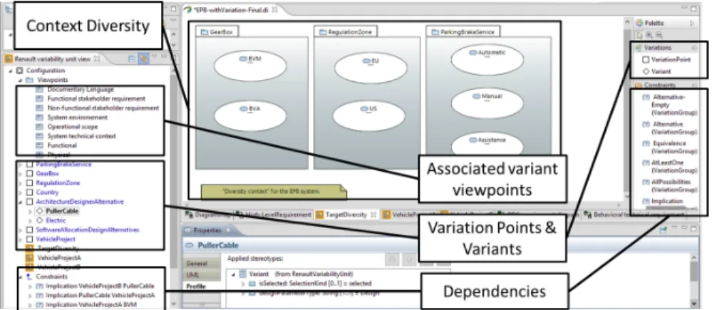
In Figure 4 we represent the context diversity for the EPB system: variants that contribute to defining the scope of the system, relative to stakeholder requirements and the system environment (e.g., the system is design only for Temperate Climate, EU countries). Usually engineers design a system for particular ranges of vehicles, meaning that they target from the start of the project certain configurations. Vari-ants and constraints for a particular vehicle project my also be represented as indi-vidual diagrams. The design should be realized with the largest possible scope of re-usability, within budget, performance and time constraints, but these initial con-figurations have to be satisfied in the first place and represent the focus of the system design.
The EPB system model contains 21 variation points with 46 related variants
repre-Fig. 4 Papyrus modeler including extensions for variability modeling Co-OVM
senting system requirements (characteristics), design decisions and choices related to components. The model also contains 36 constraints directly related to variants, and 44 constraints issued from binding to the system model and from propagation of optional elements. It is often the case that in practice, both system and constraint models are far more complex. While in the EPB case the Co-OVM model satisfied our requirements, we still have to experiment with larger system models.
7 Conclusion and perspectives
We proposed the adoption of a model for system variability in model based system engineering, based on concepts coming from the software product line literature and
existing organization practices. Our purpose was to:
• Provide explicit representation of variability during system conception for reuse of requirements and model elements across families of systems.
• Early documentation of configuration information for vehicle components in re-spect to the ”documentary language”.
• Facilitate the discovery and modeling of technical constraints for introducing them in the ”documentary language”.
We intend to further exploit the representation of variability to allow the engineer to obtain valuable information about the family of systems : calculate the cover-age of the requirements of the family of systems for partial product configurations, calculate the coverage of the vehicle range for a family of systems, calculate the coverage of all possible system configurations containing a given component, and system variability or commonality index.
References
[1] Ahn H, Kang S (2011) Analysis of software product line architecture repre-sentation mechanisms. IEEE, pp 219–226, DOI 10.1109/SERA.2011.22 [2] Astesana J, Cosserat L, Fargier H (2010) Constraint-based modeling and
ex-ploitation of a vehicle range at renaults: Requirement analysis and complexity study. In: Workshop on Configuration, p 33
[3] Becker M (2003) Towards a general model of variability in product fami-lies. In: Workshop on Software Variability Management. Editors Jilles van Gurp and Jan Bosch. Groningen, The Netherlands. http://www. cs. rug. nl/Research/SE/svm/proceedingsSVM2003Groningen. pdf, p 1927
[4] Benavides D, Segura S, Ruiz-Corts A (2010) Automated analysis of feature models 20 years later: A literature review. Information Systems 35(6):615636 [5] Chal´e G´ongora HG, Dauron A, Gaudr´e T (2012) A commonsense-driven ar-chitecture framework. part 1: A car manufacturers (nave) take on mbse. In: INCOSE 2012
[6] Czarnecki K, Gr¨unbacher P, Rabiser R, Schmid K, Wsowski A (2012) Cool features and tough decisions: a comparison of variability modeling ap-proaches. In: Proceedings of the Sixth International Workshop on Variability Modeling of Software-Intensive Systems, p 173182
[7] Djebbi O, Salinesi C (2006) Criteria for comparing requirements variability modeling notations for product lines. In: Comparative Evaluation in Require-ments Engineering, 2006. CERE’06. Fourth International Workshop on, pp 20–35
[8] Dumitrescu C, Salinesi C, Dauron A (2012) Towards a framework for vari-ability management and integration in Systems Engineering. In: 22nd Annual INCOSE International Symposium, Rome, Italy, pp 12–13
[9] Dumitrescu C, Tessier P, Salinesi C, Grard S, Dauron A (2012) Flexible prod-uct line derivation applied to a model based systems engineering process. Paris [10] Filho J, Barais O, Baudry B, Le Noir J (2012) Leveraging variability model-ing for multi-dimensional model-driven software product lines. In: 2012 3rd International Workshop on Product Line Approaches in Software Engineering (PLEASE), pp 5 –8, DOI 10.1109/PLEASE.2012.6229774
[11] Gmez A, Ramos I (2011) Automatic tool support for cardinality-based fea-ture modeling with model constraints for information systems development. In: Pokorny J, Repa V, Richta K, Wojtkowski W, Linger H, Barry C, Lang M (eds) Information Systems Development, Springer New York, pp 271– 284, DOI 10.1007/978-1-4419-9790-6 22, URL http://dx.doi.org/ 10.1007/978-1-4419-9790-6_22
[12] Halmans G, Pohl K (2003) Communicating the variability of a software-product family to customers. Software and Systems Modeling 2(1):15–36, DOI 10.1007/s10270-003-0019-9
[13] Kang KC, Cohen SG, Hess JA, Novak WE, Peterson AS (1990) Feature-oriented domain analysis (FODA) feasibility study. Tech. rep., DTIC Docu-ment
[14] Maen Tvd, Lichter H (2004) RequiLine: a requirements engineering tool for software product lines. In: Linden FJvd (ed) Software Product-Family Engi-neering, no. 3014 in Lecture Notes in Computer Science, Springer Berlin Hei-delberg, pp 168–180
[15] Mazo R, Salinesi C, Diaz D, Djebbi O, Lora-Michiels A (2012) Constraints: The heart of domain and application engineering in the product lines engi-neering strategy. International Journal of Information System Modeling and Design (IJISMD) 3(2):3368
[16] Pohl K, B¨ockle G, Linden FJvd (2005) Software Product Line Engineering: Foundations, Principles and Techniques. Springer-Verlag New York, Inc., Se-caucus, NJ, USA
[17] Possomps T, Dony C, Huchard M, Rey H, Tibermacine C, Vasques X (2010) A UML profile for feature diagrams: Initiating a model driven engineering approach for software product lines. In: Journe Lignes de Produits, p 5970 [18] Rabiser R, Grunbacher P, Dhungana D (2007) Supporting product
deriva-tion by adapting and augmenting variability models. In: Software Product Line Conference, 2007. SPLC 2007. 11th International, pp 141 –150, DOI 10.1109/SPLINE.2007.22
[19] Roos-Frantz F, Benavides D, Ruiz-Corts A, Heuer A, Lauenroth K (2011) Quality-aware analysis in product line engineering with the orthogonal vari-ability model. Software Quality Journal DOI 10.1007/s11219-011-9156-5 [20] Ruiz F, Hilera JR (2006) Using ontologies in software engineering and
tech-nology. In: Calero C, Ruiz F, Piattini M (eds) Ontologies for Software En-gineering and Software Technology, Springer Berlin Heidelberg, pp 49–102,
DOI 10.1007/3-540-34518-3 2, URL http://dx.doi.org/10.1007/ 3-540-34518-3_2
[21] Salinesi C, Mazo R, Diaz D, Djebbi O (2010) Using integer constraint solv-ing in reuse based requirements engineersolv-ing. In: Requirements Engineer-ing Conference (RE), 2010 18th IEEE International, pp 243 –251, DOI 10.1109/RE.2010.36
[22] Salinesi C, Mazo R, Djebbi O, Diaz D, Lora-Michiels A (2011) Constraints: The core of product line engineering. In: 2011 Fifth International Conference on Research Challenges in Information Science (RCIS), pp 1 –10, DOI 10. 1109/RCIS.2011.6006825
[23] Sinnema M, Deelstra S (2007) Classifying variability modeling techniques. Information and Software Technology 49(7):717–739, DOI 10.1016/j.infsof. 2006.08.001
[24] Streitferdt D, Riebisch M, Philippow K (2003) Details of formalized relations in feature models using OCL. In: Engineering of Computer-Based Systems, 2003. Proceedings. 10th IEEE International Conference and Workshop on the, p 297304
[25] Svendsen A, Haugen O, Moller-Pedersen B (2011) Using variability models to reduce verification effort of train station models. In: Software Engineering Conference (APSEC), 2011 18th Asia Pacific, pp 348 –356, DOI 10.1109/ APSEC.2011.21
[26] Tessier P, Servat D, Gerard S (2008) Variability management on behavioral models. In: VaMoS Workshop, p 121130
[27] Tseng MM, Jiao J (2001) Mass customization. In: Salvendy G (ed) Handbook of Industrial Engineering, third edition edn, Wiley Interscience In cooperation with Institute of Industrial Engineering, pp 684–710