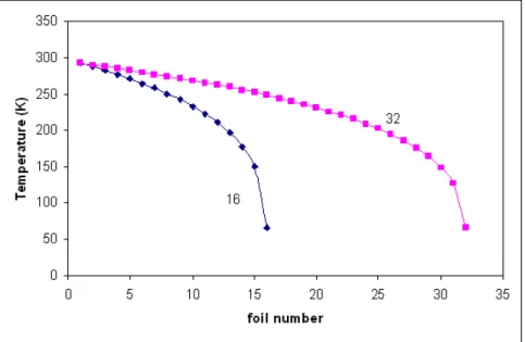
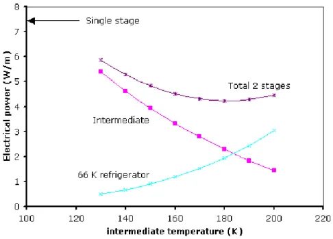
Cryostat Optimization Through Multiple Stage Thermal Shields
Texte intégral
Figure


Documents relatifs
To obtain independent evidence for the existence of a zone of disorganized glucan chains at the site of extrusion before cellulose fibril formation, we used optimized FF-TEM methods
Consequently, the problem formulation takes the form of a two-stage algorithm where the first stage (reserve market decisions) is called Medium Term Optimization (MTO) and the
Validation sur des cas simples Applications VIVABRAIN.. La simulation IRM D´ eveloppement d’un outil adapt´ e aux flux R´ esultats de simulation.. Bases physiques
Within the same context, in [23] sufficient conditions for existence and uniqueness of solutions are given for radial networks, i.e., with a single energy source, considering
ont ceci de particulier qu’ils se formulent dans le cadre d’une définition identitaire et patrimoniale à la fois locale (entre Canadiens français), nationale (défendre
When rejective sampling is used at the first-stage, the consistency of a H´ajek-type variance estimator is estab- lished under reduced assumptions, along with the asymptotic
As for the particular case of the ISA Riber MAC2 analyser (shortened to MAC2 in the following) only one publication has been dedicated to the problem: Repoux et alii [8] relied on
Thanks to the thermal and electrical models of the generator, the heat sink and the DC-DC converter, all based on experimental validation or on datasheets
