Cost Effective Design of Composite
Structure for Automotive Applications
by
Newton Eliot Mack
B.S. Mech. Eng., The University of Michigan (1994)
Submitted to the Department of Mechanical Engineering in partial fulfillment of the requirements
for the degree of MASTER OF SCIENCE
at the
MASSACHUSETTS INSTITUTE OF TECHNOLOGY June 1996
© Newton Eliot Mack, 1996. All Rights Reserved.
e:Gctr.n.:C copies of thi.·! docurrment In whole or In par
A u th o r ... ...
Newton Eliot iMack
Department/f Mechanical Engineering
May 20,1996 A pproved by ... ... .... ... Robert Faiz Technical Supervisor Draper Laboratory Certified by ... ... Dan E. Whi ey, Ph.D. Theis Supervisor
A ccepted by ... .• ...
Ain
A. Sonin, Chairman
Departmental Graduate Committee
OF TECHNOLOGY
JUN
2 71996
LIBRARIES
1
Disclaimer
This research was supported by ARPA. It represents the opinions of the author only, and is offered for the stimulation and exchange of ideas. It does not represent the policies of
the National Science Foundation, the Charles Stark Draper Laboratory, or the Massachusetts Institute of Technology.
Cost Effective Design of Composite Structure
for Automotive Applications
by
Newton Eliot Mack
Submitted to the Department of Mechanical Engineering on May 10, 1996 in partial fulfillment of the requirements
for the Degree of Master of Science at the Massachusetts Institute of Technology
Abstract
Successful use of composite primary structure in the automotive world is dependent on cost and performance criteria. The focus of this thesis is on the decision making process involving both of these factors for automotive applications. Emphasis was placed on composite materials and fabrication processes that can be used for medium volume (500-100,000 components/ year), high performance, low cost components.
A case study was made involving a 4 passenger composite electric vehicle. The cost and performance tradeoffs resulted in a vehicle using current thermoset technology and resins that provided a body-in-white weight reduction of 192 lbs or 35% over an average production vehicle at a cost increase of $438 or 39%. Based on volume price projections for
thermoplastic matrix composite material, a vehicle could be constructed that achieved similar weight loss at a 17% cost increase, or $212.
These prices are achievable at relatively low production levels of 20,000 vehicles/year, making the selected composite manufacturing methods ideal for the initially low-volume market of electric vehicles.
Thesis Supervisor: Dr. Daniel E. Whitney, Senior Research Analyst, Mechanical Engineering
Acknowledgments
This thesis could not have been completed without the help of many people. First of all, I must thank my parents, Dr. and Mrs. Newton Mack, and my brother, Adam Mack, for their continual and enduring support through my undergraduate and graduate studies. Without their encouragement this would not have been possible, and their tolerance for the changes I have gone through over the last few years is remarkable.
This work was completed at Draper Laboratories and I am grateful to them for their support and their facilities. Extensive thanks must go to Chris Stepanian as a continual source of information, encouragement, and anecdotes on many subjects, as well as a steadfast mountain biking cohort and reminder that, "It's the people, stupid." Good luck with the pedals, Chris. I must also thank Richard Bernstein for his many and varied pointers toward people and references along the way.
During the course of researching this thesis, more people took time out from their busy schedules to pass along information than can possibly be listed here. Their unselfish assistance has made the accuracy and timeliness of this study possible.
I have been fortunate to have had several advisors who have aided me in the various areas that I have studied during my stay here. Jim Gorman provided initial direction and inspiration for this project, and has continued to generously provide assistance and
support. Daniel Whitney has provided assistance and a reality check for things automotive, and Robert Faiz has generously managed to keep simultaneous and conflicting demands on a frazzled graduate student down to a rational level.
Finally, much appreciation must go to my friends both here and at MIT and in Michigan, who have been my closest source of support. I must give special thanks to Tara Arthur for many months of friendship, to Judy Chen for numerous conversations over dinner at Larry's and to John-Paul Mattia for reminding me that sometimes our most important work is not the job listed in our title. Owen Hughes and I spent many an hour sharing ideas and designing bicycles, and in general stress relief, which was needed more than can be stated. With luck one of our bicycles will actually work someday. My friends at the MIT Tae Kwon Do Club have helped to make the Institute seem a little less
institutional with their teaching and spirited dedication. I cannot conclude without
recognizing Jeff Brake and all my other friends in Michigan for being a stabilizing presence and a reminder that school is only a temporary part of the overall picture.
This thesis was prepared at The Charles Stark Draper Laboratory, Inc., under Contract 23427.
Publication of this thesis does not constitute approval by Draper or the sponsoring agency of the findings or conclusions contained herein. It is published for the exchange and stimulation of ideas.
I hereby assign my copyright of this thesis to The Charles Stark Draper Laboratory, Inc., Cambridge, Massachusetts.
Newton iot Mack
Permission is hereby granted by The Charles Stark Draper Laboratory, Inc., to theTable of Contents
A bstract ... ... 3 L ist of T ables ... List of Figures...8 1. Introduction ... ..9 1.1 Driving Forces ... 9 1.2 N A V C ... ... 11 1.3 W hy Com posites? ... . .... ... ... . ... 121.4 Purpose and Overview ... 14
2. Background ... 17
2.1 Previous Attempts At Composite Vehicles ... 17
2.2 Market Surveys & Feasibility Studies... .... 19
2.2.1 CA RB Results ... 19
2.2.2 NAVC Results ... 20
2.3 Development of Performance, Cost, and Production Level Targets...21
2.3.1 Development of Basis for Body Weight...21
2.3.2 Stiffness and Loading Requirements ... 26
3. Development of Cost and Structural Models ... 27
3.1 Cost Modeling-Basic Structure ... 27
3.1.1 Thermoplastic Stamping ... 27
3.1.2 Filament Winding ... ... 35
3.1.3 Pultrusion ... .... .... 38
3.1.4 Resin Transfer Molding (RTM) ... 40
3.1.5 Other Composite Manufacturing Processes ... 40
3.2 M aterials C ost ... 4 1 3.3 Structural Analysis of Composites ... 47
3.4 Composite Performance Data ... 49
4. Component Structural/Cost Development ... ... 53
4.1 Choice of Components... ... 53 4.1.1 Top/Bottom Shells ... 55 4.1.2 1 pc. Pultruded Floorpan ... ... 56 4.1.3 TP Roll Forming ... ... ... .... 56 4.2 B attery B ox... ... 60 4.2.1 Requirements ... ... ... ... 60
4.2.2 Manufacturing Processes Examined ... .. 61
4.2.3 Manufacturing Results ... ... ... 65
4.2.4 Conclusions ... 66
4.3 R ocker B oxes ... 67
4.3.1 Performance Requirements ... ...67
4.3.2 Manufacturing Processes Examined ... 67
4.3.3 Manufacturing Results ... ... 68
4.3.4 Conclusions ... 69
4.4 Floorpan ... . .... 70
4.4.41 Performance Requirements ... 70
4.4.2 Manufacturing Processes Examined ...70
4.4.3 Manufacturing Results ... 72
4.4.4 Conclusions ... 73
4.5 Firew alls ... ... ... ... 74
4.5.1 Performance Requirements ... 74
4.5.2 Manufacturing Processes Studied .. ... 74
4.5.4 Conclusions ... 80
4.6 Wheelwells ... ... 81
4.6.1 Performance Requirements ... 81
4.6.2 Manufacturing Processes Examined ... 83
4.6.3 Manufacturing Results ... ... 84
4.6.4 C onclusions ... ...85
4.7 Dashboard/Rear seat ... 86
4.7.1 Performance Requirements ... 86
4.7.2 Manufacturing Processes Examined ... 86
4.7.3 Manufacturing Results ... ... 87
4.7.4 Conclusions ... 87
5. Crash Structure ... ... 89
5.1 Crashworthiness-Frontal Impact/Angled Impact ... 89
5.2 Packaging Requirements ... ... 89 5.3 C oncepts ... .9 1 5.4 Performance/Materials Selection ... 92 5.5 D ynam ic Test ... . 98 6. A ssem bly ... .. 99 6.1 Adhesive Bonding ... 99 6.2 Thermoplastic Welding ... ... 101 6.3 Consolidation Results ... 104
6.4 Comparison With Steel Vehicle Benchmark ... ... 1..07
7. Summary, Conclusions, and Further Work ... 109
7.1 Summary ... 109
7.2 Conclusions ... 110
7.3 Further W ork ... 111
R eferences ... .. 112
Appendix A: Wheelwell Finite Element Results... ... 118
Appendix B: Complete Manufacturing Summary ... 120
Appendix C: Vehicle Weight/Inertia Breakdown... ... 126
Appendix D: CLPT Code ... 129
List of Tables
Table 2-1. Top Shell Areas ... 22
Table 3-1. Thermoplastic Stamping Capital Costs ... 28
Table 3-2. Thermoplastic Stamping Labor Costs ... 31
Table 3-3. Thermoplastic Stamping Tooling Costs ... 31
Table 3-4. Thermoplastic Stamping Material Costs ... 33
Table 3-5. Thermoplastic Stamping Total Costs ... 34
Table 3-6. Filament Winding Capital Costs ... 36
Table 3-7. Filament Winding Tooling Costs ... 37
Table 3-8. Pultrusion Capital Costs ... 39
Table 3-9. Low Performance Composite Materials ... 42
Table 3-10. Composite Raw Material Prices ... 44
Table 4-1. RTM Battery Box Stiffness ... 62
Table 4-2. Filament Wound Battery Box Stiffness ... 63
Table 4-3. Thermoplastic Stamped Battery Box Stiffness ... ... 63
Table 4-4. Pultruded Battery Box Stiffness ... 64
Table 4-5. Battery Box Manufacturing Costs ... ... 65
Table 4-6. Rocker Box Manufacturing Costs ... 68
Table 4-7. Floorpan Manufacturing Costs ... 72
Table 4-8. Firewall Manufacturing Costs ... 79
Table 4-9. Wheelwell Manufacturing Costs ... 84
Table 4-10. Dashboard/Rear Seat Manufacturing Costs ... 87
Table 6-1. Adhesive Bonding Costs, 500/year ...100
Table 6-2. Adhesive Bonding Costs, 20,000/year ... 100
Table 6-3. Electromagnetic Bonding Costs, 500/year ... 102
Table 6-4. Electromagnetic Bonding Costs, 20,000/year ... ...1...02
Table 6-5. Thermoset Consolidation Cost Results ... 104
Table 6-6. Thermoplastic Consolidation Cost Results ... 105
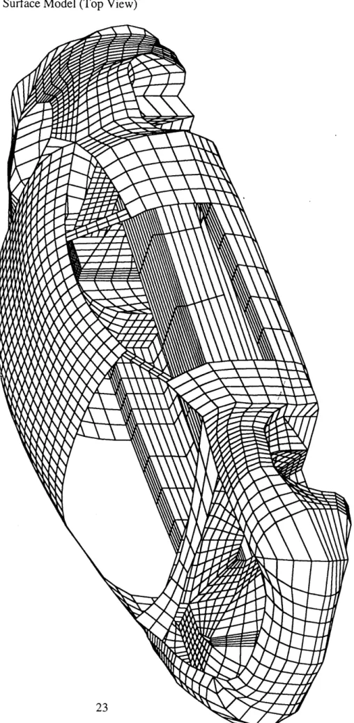
AutoCad Surface Model (Top View) ... 23
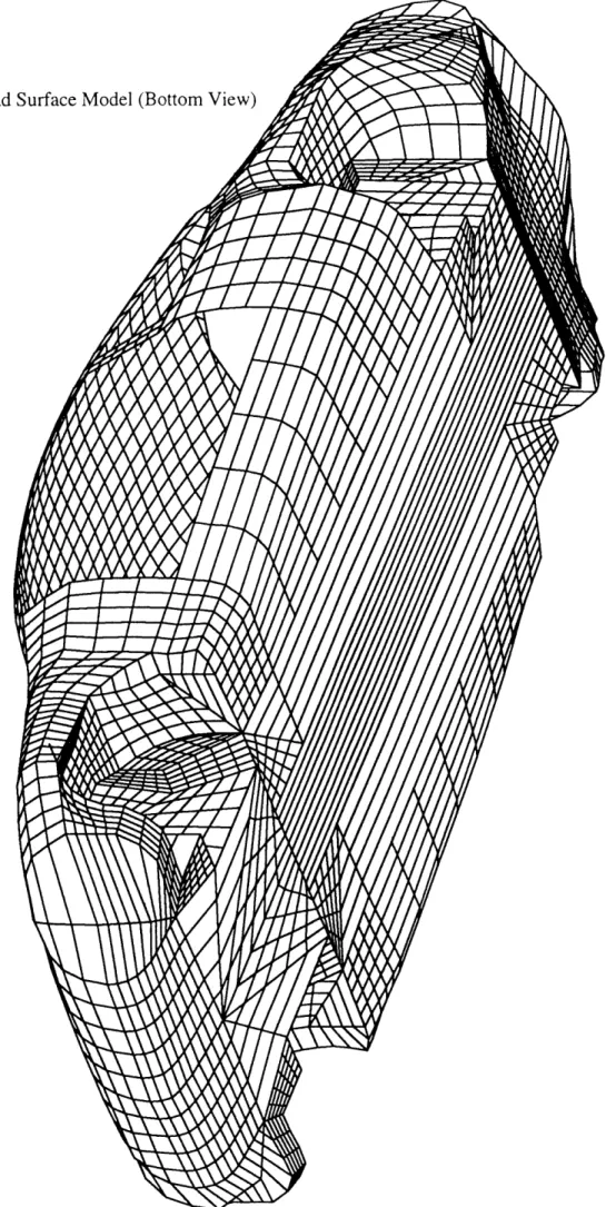
AutoCad Surface Model (Bottom View) ... 24
Vehicle Finite Element Model ... 48
View of Study Components ... 54
Thermoplastic Roll Forming Concept ... 58
Firewall/Wheelwell Consolidation Concept ... 59
Finite Element Model of Wheelwell ... 82
Side and Top View of Crushing Space ... 90
Crash Design Concepts ... 91
Material Crush Strength: High Strength Materials ... 93
Material Crush Strength: Low Strength Materials ... 94
List of Figures
Figure 2-1. Figure 2-2. Figure 3-1. Figure 4-1. Figure 4-2. Figure 4-3. Figure 4-4. Figure 5-1. Figure 5-2. Figure 5-3. Figure 5-4.Chapter 1
Introduction
1.1 Driving ForcesPersonal motor vehicles are estimated to cause nearly 30% of the carbon dioxide emissions pollution in industrial countries, and are the primary cause of the smog problem in many US cities . The problem is steadily increasing as more and more vehicles are added to the active fleet, and will become even more critical when the large populations of developing countries mobilize. Vehicle emissions have decreased markedly over the previous decades due to extensive refinement of internal combustion engines, but the problem remains.
One solution to the urban pollution problem is the use of electric vehicles. The range of an electric vehicle between required battery charges is one of the most critical factors required for public acceptance2. The main approaches available for increased mileage are an increase in the energy storage density of the batteries or a decrease in the
vehicle's mass. Extensive research has taken place in the field of increasing energy density of batteries and has produced several varieties of improved chemical storage, but with a high associated cost.
Relatively little successful effort has been directed, however, to the weight savings possible in vehicles by using composite primary structure in moderate volume commercial
of lower tooling costs, due to part consolidation and the elimination of multiple dies for a single part, and is the focus of this study.
Non-composite alternatives exist for lower weight in vehicles. Recently, a consortium of automotive manufacturers and steel producers created the Ultralight Steel Auto Body concept, which uses higher strength steels and increased use of innovative steel manufacturing techniques such as hydroforming to more efficiently meet structural
requirements. In order to compare the weight of various vehicle body material choices, the 'body-in-white' weight is used. A body-in-white in this case is the bare primered frame and does not include 'closure panels'--doors, hood, front fascia, front fenders, or rear deck lid--which are non-structural and can be made from a variety of materials. Whereas a typical body-in-white for a contemporary sedan has a weight of about 598 lbs, constituting 20-25% of the vehicle's total weight, the ULSAB concept vehicle body-in-white for the same configuration has a weight of 452 lbs3. This approach has the advantage of using steel's large existing technology base, including its complete recycling and high volume processing systems. Disadvantages include requiring multiple dies for each part and a large overall number of parts and hence dies. Die costs average $200,000-$600,000 per die, with 3-4 dies needed per individual part, causing the up front capitalization costs to be very high4. Combined with the (for now) relatively limited nature of the electric car market, it is very difficult to foresee sufficient sales of an ultralight steel electric vehicle to pay for such a high startup cost.
Aluminum vehicles have also been studied. Audi of Germany has extensive efforts under way in aluminum vehicle structures, and some welded aluminum structures have been incorporated into the next model of the Corvette. The principal problems inherent with aluminum are joining related. Spot welding is typically used in assembly of steel bodied automobiles. In automotive grade steel, spot welding produces a strong joint and does not appreciably degrade the performance of the steel alloy. Weldable aluminum alloys of sufficient strength for use in ultralight vehicle design achieve their strength by cold
working or by solution heat treating (heating the material up above 10000 F, quenching in water, and then aging the material for several hours at 300-4000 F.) Welding these alloys typically causes their yield strength to drop by nearly half in the heat-affected zone, negating much of the weight savings gained by their use.
Several other fundamental problems inhibit the adoption of aluminum. The strongest of the generally available sheet aluminum alloys are not weldable. Structural bonding and riveting must be used instead, processes that are well established in the aircraft industry, but have not achieved widespread use in automotive primary structure. This is largely due to the relative slowness of the surface preparation/bonding process (in comparison to spot welding) and to the occasional unpredictability of the bond strength. Aluminum does not have the potential of tooling savings that can be expected from
composites. Like steel, it requires multiple strikes to achieve a finished shape in aluminum, thus requiring multiple dies for a single part. Aluminum does have an extensive recycling infrastructure in place and can achieve Class-A surface finish, which is required for exterior panel applications. Recycling aluminum, however, is more difficult than recycling steel; common adhesives, paints, steel fasteners, and chemicals used in automotive applications can contaminate aluminum recycle melts and cause the recycled material to be unusable for primary use applications.
Composites offer some advantages over the previous approaches, and this study has grown out of an effort to explore the possibilities of using composites to address electric vehicles' unusual combined requirements of ultra light weight, low cost, and relatively small (500-100,000 vehicles/year) manufacturing runs.
1.2 NAVC
The NAVC (Northeast Alternative Vehicle Consortium) was created to further alternative energy technologies in the Northeast. One of the NAVC's efforts is the
promotion of small, independent, entrepreneurial electric vehicle manufacturing companies. This thesis was originally iunded out of such an effort.
The purpose of this study is twofold. The Big Three are all undertaking extensive EV development projects, and the question arises whether it would be simpler to wait for them to finish development. However, the automotive companies have a large amount of time and effort invested in the development of steel bodied vehicles and are understandably reluctant to place a composite structured vehicle into full production. One goal of this thesis is to demonstrate that ultralight composite vehicles are indeed economically feasible to manufacture.
The other purpose of this study is to demonstrate that a smaller independent manufacturer can successfully build and sell composite electric vehicles at a profit, and to provide something of a blueprint for doing so5. For this reason, all analysis tools used in this study are PC based, allowing groups with limited resources to replicate the results achieved here.
1.3 Why Composites?
Composite materials are more expensive than their homogenous counterparts. The automotive industry is largely cost-driven. There must then exist considerable reason to study the use of composite materials in automotive structural applications. There are two factors that make the future of composites promising: low weight and low startup costs.
Composites, when used properly, can provide equal performance at substantially reduced weight when compared to aluminum, steel, and most isotropic materials. The results of this study indicate that a vehicle body based on fiberglass composites can provide weight savings of 35% over a standard steel body. These savings are multiplied further by associated reduction in brake size, engine size, and drivetrain requirements.
Composites also allow for lower startup costs than steel or aluminum stamping. For example, many dozens of parts, each requiring several dies to achieve final shape, are required to make up a typical vehicle's chassis. As mentioned previously, each cast iron or cast steel die averages $200,000-$600,000. In contrast, the composite vehicle used as a case study here has only 10 parts in its structural chassis assembly, and as some of these parts are duplicates, only requires 6 mold sets due to fore/aft symmetry.
Composite materials also allow, at least initially, the use of less expensive mold materials. Epoxy based tooling is in extensive use in the aircraft industry, but its extremely limited useful life (typically several dozen parts) makes it an unattractive choice for even the low end of automotive scale production. Steel molds are still required for high volume, extended production runs, and when chrome plated provide the best release surface, surface finish, and durability of any mold. Steel molds are used in this study, as for the volumes and production runs encountered they are highly suggested, but for initial production volumes even lower than 500/year, aluminum molds become an attractive alternative and can be plaster cast to required dimensions with tolerances of +0.025 in.6
and at a much lower cost than steel molds. The plaster molds can be themselves cast from handmade prototype tools or CNC machined with extremely inexpensive (less than $1500) computer controlled routers7. This degree of inaccuracy is insufficient for high volumes
due to the cost of rework, but at the low volume, initial production levels a startup
company is capable of, cast aluminum molds seem a viable alternative. Many cost studies have demonstrated that at low volumes, composite components enjoy a cost advantage over steel components8 due to the lower capitalization and tooling costs.
In large scale (over 100,000 vehicles/year) production, the situation is somewhat different. When the production volume is sufficiently high enough to make the capital cost per part very low, the material cost dominates the component price. Despite the need for multiple die sets per part, steel's lower material cost, at $0.35/1b9, becomes economically
combined (weight averaged, 55% volume fraction, 72% weight fraction) total of
$1.24/lb' 0. Because of this, at higher volumes, or over around 100,000 units annually, steel becomes more cost competitive11".
This indicates why the auto makers have generated high resistance to introducing low volume, low cost steel body electric vehicles--at the initial low volumes expected for sales of electric vehicles, the market size is insufficiently large to pay for the tooling and startup technology around which their system of manufacturing is based. Electric vehicles are thus the province of smaller manufacturing firms until the market is large enough to justify the startup expense for steel manufacturing.
1.4 Purpose and Overview
There exists the need for a thorough study of the basic decisions and problems that would be encountered by a small firm attempting to produce an commercially successful composite electric vehicle. Possible methods for construction with composite materials vary more widely than with metallic construction, and the performance and cost of the vehicle will vary widely with the choice of processing technique. This thesis will examine viable cost and weight targets for a composite electric vehicle, the manufacturing and processing options available, and the cost/weight tradeoffs inherent in the selection of manufacturing process.
Chapter 2 will provide an overview of previous attempts at commercial composite vehicles and discern why they were not successful in the marketplace. Two market
surveys conducted to determine public factors in acceptance of electric vehicles will then be reviewed, and the results used to set weight, cost, and performance targets for the
composite electric vehicle. Chapter 3 will introduce the structural and cost models used to develop the design and manufacturing process of the composite vehicle. The process of decomposing the overall performance targets into individual component design parameters,
as well as the various manufacturing process tradeoffs, is covered in Chapter 4. Chapter 5 deals with the development and successful test of the crash control structure. Chapter 6 pulls the results of the previous chapters together with joining models and from there develops the projected construction cost of the composite structure, and compares it to current and proposed steel bodied vehicles. Chapter 7 summarizes the efforts and provides directions for future work.
Chapter 2
Background
2.1 Previous Attempts At Composite Vehicles
The concept of constructing a lightweight composite vehicle is not a new one. Various attempts at partially composite or fully composite vehicles have been prototyped several times, with some models introduced to the market. None have been commercially successful. This has typically been due to improper use of the composite material or improper choice of manufacturing process.
The Consulier GTP sports car was the most recent all composite vehicle to be introduced to the market. It was constructed by a hand lay-up vacuum bagging method with fiberglass cloth and epoxy resin over polyurethane foam cores. The vehicle
shell/chassis weighed 275 lbs out of the mold, and resulted in a finished vehicle weight of between 1850 and 2150 lbs with a Chrysler 4 cylinder engine. These vehicles were successfully crash tested and passed NHTSA, EPA, and DOT tests. Price was set at $52,50012. The vehicle was a marketplace failure, as extensive hand labor costs drove the production costs high and the vehicle possessed relatively unattractive styling. The car was, however, capable of sub-14 second quarter mile times and 34 mpg on the highway13,
and unusual combination.
Another attempt at a fiberglass composite vehicle structure prototype was conducted
metal body structure as a die model for fiberglass molds14. The laminates were created using resin transfer molding, vinylester resin, and E glass in oriented, random chopped, and continuous forms. This vehicle achieved a weight reduction of 71 lbs, but it was noted by the constructors that they had not used the material in the most rigorous manner possible and that 250 lbs of weight reduction could be achieved in a more through exercise.
The common features of the attempts made by large scale automotive manufacturers in constructing composite vehicles is their tendency to try to construct them in a fashion similar to steel cars; that is to say with materials that are mostly randomly oriented, with low fiber volumes, so that their properties become isotropic and the directionality and
stampability of the material is not an issue. However, composite materials, when not used in an oriented manner with high volume fractions (more than 50%), display little if any performance improvement over conventional materials and thus the impetus for their use in the first place is lost. Also, the auto manufacturers tend to attempt to replace steel
components with composite components on a part-by-part basis, which further lowers performance as the high stress concentrations in composite materials from bolted
attachments and the subsequent overdesign necessary to prevent failure remove much of the performance improvement. Intelligent composite construction uses component
consolidation up to the point where part yield and molding complexity begin to suffer, and then joins the components together using distributed area fastening (adhesive bonding or thermoplastic welding.)
The common features of the attempts previously made by independent composite manufacturers are intelligent use of the material properties and use of fabrication techniques ill suited to high volume and low cost. For example, the Consulier used a molding
technique that produced the entire body in one piece, but caused problems due to the high degree of hand labor required to mold the complex component. In the aerospace sphere, these slow, labor intensive production techniques are viable. This is not true for
based layup technique, but substituted the fiberglass material with carbon fiber, which caused both excessive material costs and hand labor costs.
No effort has yet been made that combines proper design and use of composite materials with the processing techniques necessary to achieve production scales.
From these attempts it can be concluded that effective weight savings using
inexpensive composite materials will only arise from the proper use of those materials; high volume fractions (50% +) and oriented fiber layups must be used instead of low volume fraction, randomly oriented and chopped fiber construction methods in areas of primary structure. A high degree of part consolidation must be achieved and primary reliance on mechanical attachment must be avoided. This must be combined with processes capable of high rates of production at a relatively low cost.
2.2 Market Surveys & Feasibility Studies
The ultimate acceptance of electric vehicles is consumer driven, and the performance and price achieved by the electric vehicle must be equivalent to the
performance and price desired by the consumer or the vehicle will fail in the market. Two major studies are summarized here.
2.2.1 CARB Results
The California Air Resources Board reviewed several market surveys to determine consumer acceptance of electric vehicles. A market survey conducted by Ford found that
60% of prospective electric vehicle purchasers require a 100 mile useful range15. This
2.2.2 NAVC Results
The NAVC conducted studies to predict the future price of electric vehicles1 7. They analyzed three cases; two conversions and one predicted purpose-built EV, which is the same vehicle studied in this thesis. For their analysis, they assumed that the running frame, including chassis, body, interior, bumpers, & other structural components, would initially cost $35,000 and would decrease to $12,000 after production was increased to 20,000 vehicles/year. These estimates were assumed based upon a predicted drop in the price of carbon fibers and a move away from hand molding to volume manufacturing processes. The assumption of a drop in the future price of carbon fiber, however, is currently somewhat in doubt, as the company that was expected to bring out a commodity priced ($5/lb) carbon fiber18 was purchased by Hercules, an aerospace carbon fiber manufacturer. The price of carbon fiber has since remained relatively steady at $18/lb for large tows1 9.
Also assumed in the NAVC study was the use of nickel metal hydride batteries. A preproduction version of these batteries powered a prototype of the composite electric vehicle used in this study to a distance of 238 miles on a single charge20. This range is certainly enough to meet most consumers' demands. The batteries are also much more lightweight than a lead acid battery pack, with a weight of 425 lbs compared to weight for a typical lead acid battery pack of around 1000 lbs. The downside to this is the cost; even in volume production these batteries are expected to cost $6000 per set.2 1
With further assumptions of standard cost reductions through volume production in the charger, electric motor, and controller system, the unit cost of a purpose built composite electric vehicle was expected to drop from $60,515 to $22,945, even allowing for the introduction of considerable capital costs ($20 million.22)
The loss of the possibility of inexpensive carbon fiber from the market may be viewed by some as a removal of hope for a lightweight composite vehicle as several auto manufacturers have attempted to construct commercially viable lightweight vehicle
constructed of fiberglass based composites without success. None of the attempts have experienced market success, for reasons detailed above, but this should not be viewed as proof that a lightweight structure cannot be constructed with fiberglass composites.
2.3 Development of Performance, Cost, and Production Level Targets
Several criteria have been set to provide a target for the economic success of the project: weight, production volume, and cost23. The weight goal was set at 500 lbs for the complete body structure, including hood, trunk, doors, dashboard, rear seat, and impact structure. The cost target was set at $2500 finished structure, or $5/lb. Production volumes were set at two different levels--a 500/year initial break-even point, and a high volume, 20,000/year full production point. For comparison with steel body-in white platforms, the surface areas and weights of the various components of the body are derived below.
2.3.1 Development of Basis for Body Weight
In order to properly decide how important weight savings are in the parts studied, a first order estimate of the weight and cost of the cosmetic elements of the body must be made. To successfully and accurately model a structure as complex as a car body, a 3D computer model (Figs. 1 & 2) of the surfaces in the vehicle was created in AutoCad. The element of the body that serves a primarily cosmetic purpose is the top shell. The top shell is composed of the following pieces:
Component name Area for one side, in2 Area for two sides, ,, Roof/Rear Deck 3100 6200 A Pillar 36 72 B Pillar 43 86 Side 832 1664 Rear Quarter 707 1414 Front Quarter 656 1312 Nose 1156 2312
Top Shell Total= 13060
Table 2-1. Top Shell Areas
Using a average skin thickness previously demonstrated in composite vehicles of 3.5 mm (. 138 in.)24 we can calculate the volume of the upper body at 1800 in3. Assuming that internal secondary support structure will add 40% to this, we have a total volume of 2500 in2 and thus the weight, using a density of .055 lb/in3 25, can be estimated at 129 lbs. Based on prototype information, doors weighed 20 lbs/ea., hood/trunk lids 8 lbs/ea., and frontal crash absorption structure 15 lbs, bringing the total to 200 lbs. At a first order finished cost estimate of $5/lb, this gives a finished manufacturing cost of $1000.
This is reasonable as technologies to create composite cosmetic parts are already well established and in use in the automotive area. Examples include the fiberglass shell of the Vette, SMC molding of many hoods and deck lids, SRIM molding of front
bumper/fascia assemblies, thermoplastic layered injection molding techniques used by IC126, XTC thermoplastic materials used by DuPont, and the Saturn side panels. Thus, the
structural components under consideration in this study must collectively weigh less than 300 lbs and cost less than $1500 to produce to meet the cost and weight targets defined earlier.
For purposes of comparison to existing steel vehicles, the composite goals can also be studied as a 'body in white'. As mentioned previously, this is simply the existing vehicle without 'closure panels'--doors, hood, trunk, front fascia, or front fenders. Using the density and surface area approximations made earlier, the weight and cost goals for a composite body in white are 420 lbs and $2,100. A benchmark average four passenger steel vehicle body-in-white (from the ULSAB study mentioned in Chapter 1) has a weight of 598 lbs and a manufacturing cost of $1,116/vehicle. The proposed ULSAB has a weight of 452 lbs and a manufacturing cost of $962 (both estimated.)
2.3.2 Stiffness and Loading Requirements
Stiffness Targets, derived from averages of steel bodied vehicles27:
Beaming (Bending stiffness requirement)= 12,200 N/mm= 1.436 e-5 in/lb deflection at center of beam
Torsional rigidity= 13,000 Nm/deg=8800 ft-lb/deg
Load cases, derived from literature28:
3 g vertical bump, front wheels, inertial relief 2g dynamic + Ig static, front wheels
2g dynamic + ig static, rear wheels 2g panic brake + vehicle dead weight
1 g lateral skid + dead weight
Of these, the 3g vertical bump with inertial relief was recognized as the most severe service load29 and will be the load case used in these preliminary tradeoffs along with the static torsional and bending requirements.
The vehicle has a projected weight of 1800 lbs with 424 lbs of batteries30, and is designed to take 4 passengers. Assuming a scenario of 4 adults averaging 150 lb each, the gross vehicle weight is estimated as 2400 lbs. This weight was found to be distributed between front and rear wheels in a 50/50 ratio31, and thus each wheel at one g will carry a load of 600 lbs, generating a maximum impulse load during the 3g vertical acceleration of
1800 lbs at the wheelwell.
Chapter 3
Development of Cost and Structural Models
3.1 Cost Modeling-Basic StructureThe basic structure of manufacturing cost modeling can be broken into 5 distinctive groups: Capital, Labor, Tooling, Material, and Energy. Despite being somewhat location dependent in terms of local labor, building, regulation, and other costs, this provides a framework to economically evaluate options.
Capital refers to the machines which produce the parts and their support equipment, Labor refers to the people who operate the machines, Tooling refers to the tools used to provide shape to the material, and Energy is the amount of power required to effect the process. To explain the process, it is easiest to demonstrate the spreadsheet model
developed and follow side by side along with it. The examples used will be thermoplastic stamping, thermoset and thermoplastic filament winding, and pultrusion. Resin transfer molding costs were calculated using a proprietary industry model that is not described in depth here but is similar in structure to the others. Raw material cost deserves special mention and thus it is dealt with at the end of the chapter.
3.1.1 Thermoplastic Stamping
Thermoplastic Stamping is a process for creating parts with complex curvature from fibers preimpregnated with thermoplastic resin. The process involves plies being cut with a
hardened steel die, stacked on a carrier, and placed into a hot press under pressure, which causes the plastic to melt and the plies to mold together. Then, the plies are quickly
transferred to a cold press and cooled under pressure which creates the interlaminar bonds. Finally, the laminate (or ply stack) is transferred to a heating oven, brought to forming temperature, and quickly shuttled into the cold forming press where it is pressed to its final shape and held until solidified. The part is removed, trimmed, and moved to assembly.
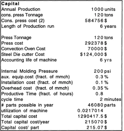
The capital cost model is arranged as follows:
Capital
Annual Production cons. press Tonnage Cons. press cost (2) Length of Production run Press Tonnage
Press cost
Convection Oven Cost Steel Die cutter Cost Accounting life of machine Internal Molding Pressure aux. equip.cost (fract. of mmch)
Installation cost (fract. of mmch) Overhead cost (fract. of mmch) Productive Time (fract. of hours) cycle time
# parts possible in year utilization of machine Total capital cost Total capital cost/year Capital cost/ part
1000 units 120 tons 584756$ 6 years 120 tons 292378$ 70000$ $124,000$ 6 yrs 200 psi 0.3% 0.1% 0.35% 0.8 2 minutes 46080 parts 0.0217014 1290417.5$ 215070$ 215.07$ Table 3-1. Thermoplastic Stamping Capital Costs
Annual production is the production run required per year; in this case, the simulation is for the 500/year study but requires 1000 parts as the same firewall is used front and rear to gain fuller utilization of the expensive mold. Consolidation press tonnage is the same as the press tonnage of the main press, and the consolidation press cost is simply the cost of 2
additional presses the size of the main press. The Press tonnage is calculated from this simple formula:
(part_ area)(proces sin g_ pressure)
tonnage =
2000
where the processing pressure is 200 psi32, and the part area for this firewall is 1000 in2.
Press Cost is determined from an study done by Masi33 and is described by: cost = $268,378 + ($200)(press_ tonnage)
To heat the consolidated laminates to forming temperature just before stamping, a multistage infrared conveyer oven is necessary. The cost of the oven ranges from
$60,000-$120,000 depending upon the complexity and rate required34; $70,000 was used for this study.
The steel die cutter cost is again based on a study in Masi35 and is roughly
$124,000. The Accounting Life of the machine is the time period over which the machine is amortized or paid for. Using 6 years is actually somewhat conservative, as a heavy press is actually serviceable for much longer than this time period, but 6 years is an accounting standard.
The Auxiliary Equipment, Installation, and Overhead costs are all estimates to approximate a series of complicated costs encountered in the machine's setup and day to day operations and upkeep. These numbers are derived from a study done by Busch36 on
industrial cost modeling.
Productive Time is a percentage of the available work hours that is actually used for part production and is a conservative average from several studies of factory work. Tool changeover time is incorporated into this estimate.
Cycle Time is the most critical number of the process, for it determines the maximum part production rate and thus the number of parts the capital cost can be
conceivably be spread over. This is derived from Quadrax•m's processing guidelines for high performance thermoplastic composites37 and is set at 2 minutes for the oriented layup components and 1 minute for the randomly oriented components (dashboard, floorpan, and rear seat.) This seems to be somewhat conservative; some thermoplastic material
manufacturers have demonstrated cycle times of well under 30 seconds.38
# Parts Possible describes the quantity of parts that can possibly be produced with respect to cycle time, working hours, and productive time:
# parts = (working_ hours)( productive_ fraction)(60_ min s / hour) cycle_ time
Utilization of Machine describes the fraction of the machine's time that is actually used for this production run:
utilizatio= annual production run
Total Capital Cost is the complete cost of the capital equipment.
( auxeq_ $ + '
install $ +
total-cost = * main_ $ + oven $ + die $ + 2(consd_ $) overhead_ $ +
Capital Cost/Year is the total capital cost divided by the accounting life of the machine, and Capital Cost/Part is the Capital Cost/Year divided by the annual production run.
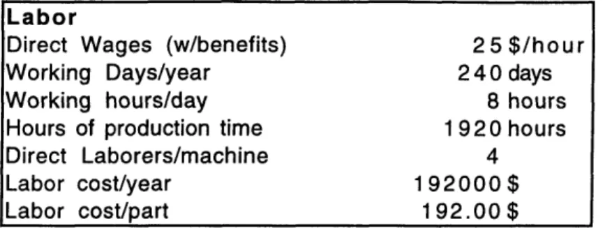
Labor is simply the cost of the people operating the machines. Labor rates were assumed to be $25/hour, with a workweek comprising 5 days at 8 hours per shift for a total of 1920 hours per year, as shown in the spreadsheet excerpt below. Double shifts, 16 hours/day, were used at higher production volumes when necessary.
Labor
Direct Wages (w/benefits) 25 $/hour
Working Days/year 240 days
Working hours/day 8 hours
Hours of production time 1 920 hours
Direct Laborers/machine 4
Labor cost/year 192000$
Labor cost/part 192.00 $
Table 3-2. Thermoplastic Stamping Labor Costs
4 laborers are assumed to work on this machine line, so the labor cost/year and labor cost/part are direct functions of the above conditions and of the production schedule.
Tooling is one of the most costly aspects of preparing for a production run; presses and other general equipment can be used for several different parts, but tooling is part specific.
Tooling
Tooling 152221 $
Rough cutter die cost 1200 $
# of passes req'd 1 passes
Life of tooling 6 years
Cost/year of tooling 25570 $
Cost/part of tooling 25.57$
Table 3-3. Thermoplastic Stamping Tooling Costs
Two sided, matched metal tooling is assumed in this case; the equation describing matched tooling cost as a function of area is39:
[0.22 *454 *part_weight+.423 *projected part_area *2.542+339]*20/tool materialfactor The tool material cost factor mentioned above is 0.5 for P20 steel and 2.35 for aluminum. P20 steel is assumed for all calculations in this study.
die_cost=$1000+ $19*perimeter/12
The life of the steel tooling used for composite forming is quite high and it is unlikely tt,.. proposed production volumes of composite electric vehicles will be sufficient to wear out steel tools; however, the accounting life of the tool provides an accurate assessment of the distributed cost of the tool as the vehicle will be updated at least every six years. The cost/year of tooling is simply the initial cost divided by the accounting life, and the tooling cost/part is the cost/year divided by the annual production run.
It must be noted here that some studies have encountered difficulty in forming thermoplastic composite parts with matched metal tooling; the rapid cooling of the
composite caused by contact with the cold metal causes loss of formability and subsequent tearing or fiber distortion41. For this reason, the male half of the tool is typically a metal form over which has been cast a silicone block to match the female tool. This provides even consolidation at lower cost but does not provide the same two sided tooled surface accuracy of steel tooling, which is useful to avoid tolerance buildup in the complex joining surfaces of road vehicles. For this reason, a composite tool comprised mainly of an
elastomer punch but with matched metal surfaces where necessary for joining operations is assumed in use where necessary; it is also assumed that this will have a cost similar to that of a matched metal tool.
As mentioned previously, material cost is simply the weight of the component multiplied by the cost/lb of the material in question. Scrappage is ignored in this study due to difficulty of prediction; it is recognized that this is not a trivial cost in composite
manufacturing due to the high cost of the material and further study is indicated in this area. It is assumed every effort to minimize waste will be made, including recycling of waste material into non primary structure components such as cosmetic panels and interior supports.
Table 3-4. Thermoplastic Stamping Material Costs
Energy cost in this case is assumed to be largely due to the operation of the preheating oven; as this is further assumed to be a 200A, 440V rms oven, the power consumption is found to be (200A)(440V)=88 kW. The number of kilowatt-hours of energy used in a year is simply the operational hours times the power consumption; in this case (1920 hours/year)(88 kW)= 169 MWh/year. Cost of energy varies with location but is assumed to be $0.08/kWh for a total of $13520/year. This cost is multiplied by the
utilization of the machine and divided by the number of parts produced to gain energy cost/part figures.
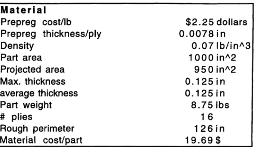
Drawing these various components together, we can find the overall cost of the component:
Material
Prepreg cost/lb $2.25 dollars
Prepreg thickness/ply 0.0078 in
Density 0.07 Ib/in^3
Part area 1000 in^2
Projected area 950 in^2
Max. thickness 0.125 in
average thickness 0.125 in
Part weight 8.75 Ibs
# plies 16
Rough perimeter 1 26 i n
Table 3-5. Thermoplastic Stamping Total Costs
The costs at top are simply the previously mentioned costs added up; as you will notice, this produces an extremely expensive part for small production runs. For a more realistic assessment of the actual cost of the part, we will assume that, at volumes low enough that a single part's production utilizes only a tiny fraction of the available machine capacity (2.2% in the example above), several parts would be made from the same production line, using the capacity more thoroughly, and the capital, labor, and energy costs would be changed to reflect this distributed use. This is called utilization based cost. In this case, nearly 50
similar parts would need to be run from the same line; this is a difficult task considering the degree of parts consolidation expected in the vehicle. This difficulty is reflected in the conclusions in Chapter 4 on process selection.
Costs
Capital cost/ part 215.07$
Labor cost/part 192.00$ Tooling cost/part 25.57$ Material cost/part 19.69$ Energy cost/part 13.52$ Total cost/part 452.94$ Cost/Ib $51.76 $
Costs (utilization base)
Capital cost/ part 4.67$
Labor cost/part 4.17 $ Tooling cost/part 25.57$ Material cost/part 19.69$ Energy cost/part 0.27$ Total cost/part 54.10 $ Cost/lb 6.20$
Material cost is unaffected by this change, for the same amount of material is used per part no matter what the production run, and likewise tooling is not affected because one tool cannot be used for any other purpose but to make the part it was designed for. Thus, for utilization based cost, the capital, labor, and energy costs are multiplied by the
utilization of the machine that particular run actually uses, providing greatly reduced costs. A word of caution must be spoken here; the lowered costs shown in the utilization based figures can only be realized if the machine is indeed fully utilized; thus the dies and the material feed line have to be rapidly reset for each new component. This is the
centerpiece of the lean production system developed in Japanese automobile manufacturing plants. For accurate cost analysis, the actual utilization of the machine must be measured in practice and results derived from that.
3.1.2 Filament Winding
For Filament Winding (thermoset and thermoplastic), the model is much the same as the thermoplastic stamping model with the exception of the Capital and Tooling costs, which are studied here. This model is based on a study by Busch42 but in a more simplified form.
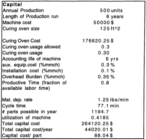
Capital
Annual Production
Length of Production run Machine cost
Curing oven size Curing Oven Cost
Curing oven usage allowed Curing oven usage
Accounting life of machine aux. equip.cost (%mmch) Installation cost (%mmch) Overhead Burden (%mmch)
Productive Time (fraction of available labor time)
Mat. dep. rate Cycle time
# parts possible in year utilization of machine Total capital cost Total capital cost/year Capital cost/ part
500 units 6 years 50000$ 1 25 ft^2 176620.25$ 0.3 0.30 6 yrs 0.3% 0.1% 0.35% 0.8 1.25 Ibs/min 77.1 min 1194.7 0.4185 264120.25$ 44020.01 $ 88.04$
Table 3-6. Filament Winding Capital Costs
This model was calculated using the 500 units/year benchmark. Machine cost was set at $50,000 each, with a material deposition rate of 1.25 lbs/min43. This allows the cycle time to be derived according to the following equation:
part_ weight cycle_ time =
deposition_ rate
The number of machines needed for a given production goal can be calculated as follows:
#_machines= annual_ production production / machine
using methods similar to those used in the thermoplastic stamping model.
Oven size follows as a direct consequence: the curing time of the materials used is about 3 hours44and so the number of parts cured in 3 hours must match the number of
parts wound in 3 hours. As the cycle time for the part in question is 51 minutes, 4 parts must be cured simultaneously to match the rate. Each part is 9 cubic feet in volume, and limiting the usage of the oven to 30% of its volume capacity to allow adequate airflow45 necessitates an oven of sufficient size:
ovensize = (part_ volume)(# _ cured) volume_ utilization
Oven cost is calculated according to an equation derived by Masi46. oven_cost= $12,129+($1315.93)(oven_volume, ft3)
Mandrel changeover time is incorporated into the Productive Time fraction. Total capital costs and annual/part capital costs are calculated similarly to the thermoplastic stamping model.
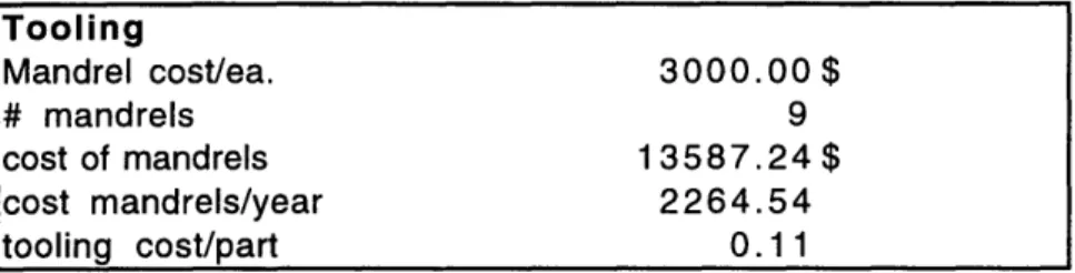
Tooling costs consist of the mandrels required for production.
Table 3-7. Filament Winding Tooling Costs
The mandrel cost for the battery box is $300047, and the number of mandrels required is twice the number that are curing in the oven at any given time (one set of mandrels is continuously being wound while the other set is curing.)
# mandrels = 180- min. x2 cycle- time)
Total mandrel cost, cost of mandrels/year and tooling costs/part are all straightforward. Labor is calculated similarly to the thermoplastic stamping model except that only one
Tooling Mandrel cost/ea. 3000.00$ # mandrels 9 cost of mandrels 13587.24 $ cost mandrels/year 2264.54 tooling cost/part 0.11
operator on average is assumed. Similarly, the cost of energy based on oven use is calculated similarly to that of thermoplastic stamping. The mandrels are assumed to be collapsible, thereby removing the need for expensive hydraulic puller equipment to separate the cured part from the mandrel.
Thermoplastic filament winding is calculated similarly to thermoset filament winding except that the material deposition rate is lower (0.62 lbs/min48), there is no oven used for curing, and there are only two mandrels required as the part can be removed from one while the other is being wound. The base machine cost increases by $5,000 due to the addition of a gas torch49 to heat the material as it is deposited on the mandrel. Also, energy cost is assumed negligible due to the lack of an oven in continuous operation.
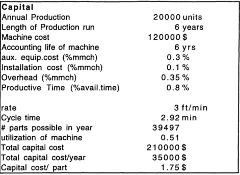
3.1.3 Pultrusion
Pultrusion receives special attention as it is known to be one of the lowest cost methods of producing composite parts due to rapid processing and its highly automated nature. The pultrusion cost model is set up similarly to the others, with capital, labor, tooling, materials, and energy cost.
Capital
Annual Production Length of Production run Machine cost
Accounting life of machine aux. equip.cost (%mmch)
Installation cost (%mmch) Overhead (%mmch)
Productive Time (%avail.time) rate
Cycle time
# parts possible in year utilization of machine Total capital cost Total capital cost/year Capital cost/ part
20000 units 6 years 120000$ 6 yrs 0.3% 0.1% 0.35% 0.8% 3 ft/min 2.92 min 39497 0.51 210000$ 35000$ 1.75$
Table 3-8. Pultrusion Capital Costs
The 20,000/year production case is demonstrated. Main machine cost is set at $120,00050 and obtains a production rate of 3 ft/min51. Cycle time is thus calculated as:
cycle_ time = part_length pultrusion_ rate
Capital costs are then calculated similarly to previous models.
Tooling for pultrusion is typically chrome plated steel to withstand the high pressures and temperatures of the pultrusion process. Pultrusion die cost for this
application is estimated at $150,00052. Tooling cost/part is calculated similarly to previous models.
Labor for pultrusion also assumes an average of only one person working on the machine, as the process is highly automated. Labor cost/part calculations are otherwise identical to those previously studied. Energy costs are assumed negligible as the only component heated is a relatively small die kept at constant temperature.
3.1.4 Resin Transfer Molding (RTM)
Resin Transfer Molding is a process by which a dry fiber preform is die cut, stamped into shape, and placed into a matched mold. The mold is then placed into a press to provide sufficient pressure for high volume fraction results and evacuated to remove any air remaining. Resin is then 'transferred' into the mold from outside tanks, typically through a mixing nozzle. The mold is heated and cooled to cure the resin.
The resin transfer molding cost model used for this application is a proprietary industry model of a structure similar to the previously mentioned cost models. Identical costs are assumed for the matched metal toolsets for RTM and thermoplastic stamping. Resin transfer molding is a relatively slow process, with cycle times generally around 30 minutes required for high volume fraction, high performance component manufacturing, which is the cycle time assumed for these cost calculations. Thus, the process is not capable of spreading out the cost of a matched tool set over a large number of parts to the degree that thermoplastic stamping is. However, this is somewhat offset by the lower cost of the raw materials, as mentioned previously, and the lower capitalization costs;
production capable resin transfer molding machines are available at prices as low as $25,00053. Press costs can be calculated using the same equations used as those for thermoplastic stamping presses.
3.1.5 Other Composite Manufacturing Processes
There are many other automated composite manufacturing processes that were not included in the cost/performance tradeoffs as they lack high volume fraction capability. Structural Reaction Injection Molding is a high speed method of composite part
manufacturing in which a preform is placed into a high pressure mold and a two part resin is injected into the mold at a very high rate of speed and pressure. This process produces low cycle times, on the order of 5 minutes, but is generally not capable of over 35-40% volume fraction. This process is effective, however, for items such as suspension links
that are not bending or torsional stiffness driven and are more typically sized for external impact or damage tolerance.
Vacuum based, single sided tool processes, using a flexible elastomer diaphragm or disposable bag, are popular due to their low capital cost. Vacuum based resin transfer type molding systems without a source of extra pressure on the diaphragm side are typically not consistently capable of over 40% volume fraction in a manufacturing environment,
however, which removes these systems from consideration. Likewise, vacuum assisted forming for thermoplastic materials is a popular and inexpensive method, and the
preimpregnation of the thermoplastic fibers at the prepregging facility removes the difficulty of achieving high volume fractions. This process has limitations, however, in the thickness of laminate that can be successively thermoformed; this limit is typically about 0.080" thick54 and is thus not sufficient for the thicker laminates used in the construction of this composite vehicle.
3.2 Materials Cost
Materials cost is one of the most fundamental obstacles to the widespread adoption of composite materials in automotive applications. As such, it requires close examination.
One of the primary choices to be made in the arena of composites is whether to use a thermoset or a thermoplastic resin. The thermoset resins are more familiar and have a wider base of use, while the thermoplastic resins offer the promise of lower manufacturing costs and recyclability, and their prices are continually decreasing. It is impossible at the
outset to say with certainty which is the better choice, and so this study will look at both families to determine their relative strengths and weaknesses.
Within the thermoplastic and thermoset families, there are several levels of cost and performance. There are commonly available families of long fiber random oriented 'mat' products oriented at the automotive body panel market which provide relatively low
mechanical properties but offer rapid processing cycles and low cost (for example, volume pricing for XTC is $1.50/lb at 50,000 lbs/year, achievable at the 500/year volume
production level, to $1.35/1b at 250,00 lbs/year, achievable at the 20,000/year production level.)55
These are represented by the following commercial product names:
Material Modulus
GE: Azdel (random) 0.956 Msi
Azdel (directionalized) 1.4 (Parallel) 0.7 (Transverse) Msi Azmet (random) 1.2 Msi
Azloy (random) 1.1 Msi
DuPont: XTC 1.157 Msi
SMC-R40 1.9 Msi
Table 3-9. Low Performance Composite Materials
These materials do not have sufficient performance to be used in primary automotive structure; their stiffnesses and strengths are resin dominated and thus they are relegated to primarily cosmetic components.
Thermoset materials exist in commodity form as glass unidirectional fibers wound on creels or woven into cloth and raw resins. Polyester resins are the least expensive ($1.23/lb typical) and have the least desirable properties in strength, creep, shrinkage, and impact resistance. Vinylester resins are more expensive (typically $1.70/lb) and have slightly improved properties over polyester. Epoxy resins are the highest cost ($5+/lb) and the highest performance. Polyester resin was chosen for this application as the improved properties of vinylester and epoxy were not judged sufficiently high to overcome the
springs, epoxy resins are typically used as their creep resistance is superior to that of the vinylesters and polyesters.
There are also an increasing number of high performance thermoplastic composites on the market which have high mechanical properties by virtue of their unidirectional or woven construction and high volume fractions of glass fiber. The most common low cost resins currently used and studied include PPS (polyphenylene sulphide), PEI (polyether imide), PP (polypropylene), PET (polyethylene terapthalate) and variations of nylon. Thermoplastic matrix composite materials are not yet in widespread use; however, some work has been done to characterize these materials for creep properties58, and basic
stiffness and strength properties are available from manufacturers' product information. A word should be said about creep properties of thermoplastic composites, as these are expected to be inferior to thermoset composites. Available literature has indicated that creep is not evident in fiber dominated directions but is evident in matrix dominated
directions. One example of matrix dominated creep would be tensile or compressive forces on a [_+45] laminate instead of shear forces. Every effort has been made in this study to ensure that the laminates are loaded only in the directions dominated by fiber, as this is the method that uses the properties of the fibers to the greatest effect.
Thermoplastic materials are currently relatively expensive materials in the prepreg form ($4/lb-$15/lb) but as the raw material costs of the combined constituent materials and resins are low59 and the processing steps are straightforward60 their cost should steadily
decrease toward the levels demonstrated on the following chart. The cost of prepregging is a cost that is estimated, for high production volume thermoplastic prepregging, to come down to $1/lb 61. This is not unprecedented; impregnation costs in SMC are typically
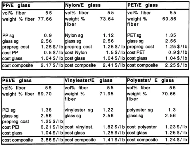
$0.25/lb-$0.35/lb, although the process is not controlled as closely. The entire material cost for DuPont XTC PET/E glass, including prepregging, is around $1.40/lb as mentioned previously. $1.25/lb costs are assumed to allow for materials supplier profit margins. Vinylester/E glass and polyester/E glass are included in the chart for reference to
common thermoset prices. 'sg' in the chart refers to 'specific gravity' of the material indicated; this is the material's density with respect to pure water, which has a sg of 1.
PP/E glass Nylon/E glass PET/E glass
vol% fiber 5 5 vol% fiber 5 5 vol% fiber 55
weight % fiber 77.66 weight % 73.64 weight % 69.86
fiber fiber
PP sg 0.9 Nylon sg 1.12 PET sg 1.35
glass sg 2.56 glass sg 2.56 glass sg 2.56
prepreg cost 1.25 $/lb prepreg cost 1.25 $/lb prepreg cost 1.25 $/Ib cost PP 0.5 $/lb cost Nylon 1.5 $/lb cost PET 0.9 $/lb cost glass 1.04 $/Ib cost glass 1.04 $/ I b cost glass 1.04 $ /I b
ost composite 2.17 $/lb cost composite 2.41 $/Ib cost composite 2.25 $ /I b
PEIIE glass Vinylester/E glass Polyester/ E glass
vol% fiber 55 vol% fiber 5 5 vol% fiber 55
weight % fiber 69.70 weight % 71.95 weight % 70.65
fiber fiber
PEI sg 1.36 vinylester sg 1.22 polyester sg 1.3
glass sg 2.56 glass sg 2.56 glass sg 2.56
prepreg cost 1.25 $/lb
cost PEI 6.21 $/Ib cost vinylest. 1.82$/lb cost polyester 1.23$/Ib
cost glass 1.04 $/I b cost glass 1.25 $/1 b cost glass 1.25 $/I b
cost composite 3.86 $/I b cost composite 1.41 $/I b cost composite 1.24 $/1 b
Nylon/carbon vol% fiber 55 weight % fiber 66.27 Nylon sg 1.12 carbon sg 1.8 prepreg cost 1.25 $/lb cost Nylon 1.5 $/lb cost carbon 1 8 $/lb cost composite 13.68 $/Ib
The main tradeoffs in selection of thermoplastic resins are cost, impact resistance, chemical resistance, processability, and service temperature62. PPS has excellent
resistance to most solvents, and, in a toughened form, has high impact resistance . Its glass transition temperature, and thus its service temperature, is relatively low-only 830C,
which could cause problems in hot environments. Fundamentally, however, its chief detriment is its high price/lb, which will be seen to dominate thermoplastic manufacture and force the choice of polymer.
Nylon derivatives are chemical resistant and posses high glass transition
temperatures (2800C) but are hydroscopic and absorb water, in some cases up to 5% by weight. This typically causes a severe decrease in compressive strength properties when it is fully saturated (30% loss after immersion for 5 days.)63 However, they offer good performance through their strong adhesion to fibers and consequently are used in several sporting goods applications, such as the GT LTS-1 carbon fiber bicycle frame and the SPIN Composites injection molded carbon fiber/nylon tri- spoked bicycle wheel. Current prepreg costs at high volumes are $4/lb.
PEI in its raw resin form is expensive at $6.21/lb. The composite material cost is estimated at $3.35/lb. PEI offers a high glass transition temperature (2400C), ease of processing, and very high toughness. The chemical resistance of PEI was once a problem, but recent resins from GE Plastics/Cyanamid Co. such as Cypac X7005 have been
formulated to address this problem. However, commercial PEI/composites are typically oriented toward graphite fibers due to the high cost.
PP composites have the benefit of being very inexpensive. PP/E glass is produced commercially for $3.50-$4.00/b 64, which can be expected to decrease under high volume production runs. However, they are severely limited by their temperature range and are not considered applicable for primary structure applications that will see the high temperatures experienced by automotive applications.
Polycarbonate materials are attacked by ultraviolet light and by aromatic
hydrocarbons such as gasoline and are thus impractical for extensive use in automotive environments.
For automotive purposes, the extreme low cost of PET composites, combined with fair strength performance and excellent resistance to chemicals, impact, and temperature seem to be the most favorable combination. The environmental resistance and service performance of these composites have also been indicated by industry experts65 to be superior to the nylon and PP based composites, and a large, low cost supply of the polymer material exists as regrind from recycled soft drink containers. This material is being developed commercially and is expected to be available for $2.25/lb in quantities of