HAL Id: hal-02099827
https://hal-amu.archives-ouvertes.fr/hal-02099827
Submitted on 25 Apr 2019
HAL is a multi-disciplinary open access
archive for the deposit and dissemination of
sci-entific research documents, whether they are
pub-lished or not. The documents may come from
teaching and research institutions in France or
abroad, or from public or private research centers.
L’archive ouverte pluridisciplinaire HAL, est
destinée au dépôt et à la diffusion de documents
scientifiques de niveau recherche, publiés ou non,
émanant des établissements d’enseignement et de
recherche français ou étrangers, des laboratoires
publics ou privés.
A novel setup for 3D chasing behavior analysis in free
flying flies
Léandre Varennes, Holger Krapp, Stéphane Viollet
To cite this version:
Léandre Varennes, Holger Krapp, Stéphane Viollet.
A novel setup for 3D chasing behavior
analysis in free flying flies.
Journal of Neuroscience Methods, Elsevier, 2019, 321, pp.28-38.
A novel setup for 3D chasing behavior analysis in free
flying flies
Léandre P. Varennes
a,b,⁎, Holger G. Krapp
a, Stéphane Viollet
baDepartment of Bioengineering, Imperial College London, SW7 2AZ London, UK
bAix-Marseille Universite, CNRS, Institute of Movement Science, UMR 7287, Marseille 13288, France
A R T I C L E I N F O Keywords: Aerial pursuit Freeflight Blowfly Invertebrate pursuit Capture strategies Insect vision Neuroethology Fly body orientation
A B S T R A C T
Background: Insects catching prey or mates on the wing perform one of the fastest behaviours observed in nature. Some dipteranflies are aerial acrobats specialized to detect, chase and capture their targets within the blink of an eye. Studies of aerial pursuits and its underlying sensorimotor control have been a long-standing subject of interest in neuroethology research.
New method: We designed an actuated dummy target to trigger chasingflights in male blowflies. Our setup generates arbitrary 2D target trajectories in the horizontal plane combining translation up to 1 m/s and angular rotation up to 720°/s.
Results: Using stereovision methods we reconstructed target and pursuer positions every 5 ms with a maximum 3D error of 5 mm. The pursuer's body pitch and yaw angles were resolved within an error range of 6deg. An embedded observation point provides a close-up view of the pursuer'sfinal approach and enables us to measure its body roll angle. We observed banked turns and sideslip which have not been reported for chasing blowflies in the past.
Comparison with existing method(s): Previous studies focused on pursuit along circular paths or interception of translating targets while our method allows us to generate more complex target trajectories. Measurements of body orientation in earlier accounts were limited to the heading direction while we extended the analysis to include the full body orientation during pursuit.
Conclusions: Our setup offers an opportunity to investigate kinematics and governing visual parameters of chasing behaviour in species up to the size of blowflies under a large variety of experimental conditions.
1. Introduction
Flying insects are one of the most manoeuvrable animals on the planet. We often take the example offlies escaping from an attempt to swat them as a demonstration of their fast reactions, but their airborne chasing behaviour is even more impressive. Taking advantage of its exceptional manoeuvrability, the chasing fly is capable to deal with unpredictable trajectory changes and evasive tactics of its target while avoiding obstacles. Fly sensory-motor responses to correct their tra-jectories kick in only about 20 ms after course changes of its target (Collett and Land, 1975) as a result of neuronal processing delays and the time it takes steering motor action to become effective. Previous studies have been aiming to observe and understand the complexity of chasing flights and its underlying control at different systems levels (Egelhaaf and Borst, 1993).
Chasing has been characterized under natural freeflight condition in various species: the housefly Musca (Wehrhahn, 1979; Wehrhahn
et al., 1982; Wagner, 1986a), its smaller relative Fannia (Land and Collett, 1974), patrolling males (Zeil, 1986), the hoverflies Syritta
(Collett and Land, 1975), Eristalis and Volucelle (Collett and Land, 1978), and dilochopodidflies (Land, 1993). Similar types of experi-ments were performed on dragonflies capturing Drosophila (Olberg et al., 2000; Mischiati et al., 2015).
In the late 1970s, Collett and Land observed that hoverflies pursued a cherry core after one of them spit one near a bush, inspiring the scientists to build a pea-gun for studying theflies’ pursuit reflex (Collett and Land, 1978). Much later in early 2000s, to elicit prey capture
Olberg et al. (2007)attached a bead to afishing line and moved it by hand in the same plane as a perching dragonfly. In a recent study on dragonfly pursuit,Mischiati et al. (2015)also used a beadfixed on a transparentfishing line. This time the bead moved in straight line, at a computer-controlled speed, with height-adjustable pulley system. A similar study has been performed with robberflies by Wardill et al. (2017)and a much smaller aerial predator, the killerfly (Wardill et al.,
⁎Corresponding author at: Institut des Sciences du Mouvement, Bât soufflerie - CP 910, 163 avenue de luminy, 13009 Marseille, France.
E-mail addresses: [email protected],[email protected](L.P. Varennes), [email protected](H.G. Krapp),
[email protected](S. Viollet).
https://doi.org/10.1016/j.jneumeth.2019.04.006
differences result in the major advantage regarding the power required to move the cart carrying a given amount of payload (see below). First, an extra couple of pulleys change the belt circuit, enabling the belt to cross outside of the working range (seeFig. 1B). The second difference
concerns the 4 attachment points establishing the link between the belt and the cart as opposed to only two in the H-frame design. Distributing the effort equally over 4 attachment points means that we can move an heavier payload on the cart for the same amount of power generated by the motors. The ceiling of theflight arena is made of white fabric that slides gently over the main structure when the cart moves, which pre-ventsflies to escape during experiments. The moving cart inFig. 1C supporting the rotating target is composed of two co-axial shafts: (i) a fixed inner shaft (diameter 6 mm) containing the light guide of an embedded camera and preventing connected wires to twist, as well as (ii) a rotating outer shaft to which a rod holding the target and, at the end, a tilted mirror are attached.
The outer shaft (in red inFig. 1C) is actuated, through a belt, by a small stepper motor (Faulhaber, AM0820-V5-56, reduction gear ratio of 1). The latter is controlled at a resolution of 1200 steps per revolution allowing for a maximum rotational speed of 720°/s.
Target movements are thus controlled along the two translational degrees of freedom in the horizontal plane by the CoreXY system and one rotational degree of freedom by the mounted stepper motor. The CoreXY system alone reaches translations of up to 1 m/s, which can be combined with maximum angular velocities of two revolutions per second, enabling large variety of target movements. The target is placed 15 cm below the ceiling and can reach any position within thefloorplan of the arena.
Translation: In the following we give the equations of motion the CoreXY generates. The two actuators are the two stepper motors A and B and the moving object is the cart (seeFig. 1B). Activating only one motor while keeping the other one still results in linear motion of the cart. Positive rotation (counter clockwise) of motor A while holding motor B still results in diagonal cart movement in the positive x- and positive y- direction, while a negative rotation of the same motor causes a movement in negative x- and negative y-direction. This can be written as:
= +
A X Y
Δ Δ Δ (1)
Activation of motor B, while keeping motor A stationary, moves the cart along the other diagonal. In this case positive rotation of motor B results in a movement of the cart in positive x- and negative y-direction.
= −
B X Y
Δ Δ Δ (2)
Combining Eqs. (1) and (2), we obtain the movement of the cart along the x- and y-axis as a function of activation of motors A and B:
⎧ ⎨ ⎩ = + = − X A B Y A B Δ 1/2(Δ Δ ) Δ 1/2(Δ Δ ) (3)
We can describe the general relationship between the rotation of the motor pulley and the displacement of the belt moving the cart by:
=
M r ϕ
Δ Δ M (4)
Where r the radius of the motor pulley,ΔϕMis the number of
an-gular steps (in radians) in theϕMdirection, andΔM is the displacement
of the belt. Thus, by substituting the activity of motors A and B in Eqs. (3) and (4) we obtain the movement of the cart along x- and y-axis as a function of the rotation of motors A and B.
⎧ ⎨ ⎩ = + = − X ϕ ϕ Y ϕ ϕ Δ rR/2(Δ Δ ) Δ rR/2(Δ Δ ) A B A B (5)
We used a GT 5 mm timing belt mounted on step motors pulleys of 30 teeth. By adding micro-step drivers (with reduction ratio R), we can increase in precision the displacement of the cart. In our system r = 23.85 mm and R = 1/4.
Rotation: The rotation of the target around the center of the cart is
2015). To summarize, targets triggering interception behavior were
moved by hand, shot at a close proximity of pursuers or moved at various speeds along straight trajectories.
Boeddeker et al. (2003) reported the first study on chasing behavior where the speed of a dummy target was controlled more systematically. Male blowflies were pursuing a black sphere (dummy) moving at con-stant speed along a circular path of 10 cm radius. In a series of ex-periments, the speed (1/1.25/1.5 m/s) and the size (5/8/13 mm) of the target were varied, revealing the parameter combination required for male flies to capturing the dummy. The scientists also provided a model describing the dynamics of the male blowfly's chasing flights in the horizontal plane. However, despite the excellent repeatability of the behaviour, the comparatively regular dummy trajectories used in those experiments are quite different from the complex trajectories observed under more realistic conditions. To overcome these limitations, we developed a method that enables us to study chasing behaviour in male flies confronted with target trajectories which more closely approx-imate the female flight dynamics. Here we describe (i) the system that controls target motion, including its mechatronics, (ii) a high speed camera-based 3D tracker based on which dummy and fly trajectories are reconstructed, as well as the orientation of the pursuer (yaw- and pitch-) and (iii) preliminary experimental results obtained with the blowfly Lucilia sericata. The setup can be upgraded with a novel ob-servation system that provides high quality imagery of the pursuer's final approach offering valuable details of the capture phase, and measure of the body roll.
2. System description 2.1. Principle of operation
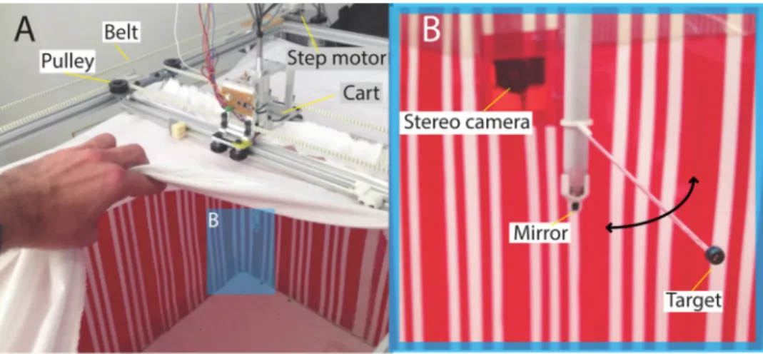
The custom-made flight arena is a rectangular volume of 70 × 50 × 50 cm. Flies have a spectral sensitivity slightly shifted to lower wavelengths compare with humans, excluding the red color spectrum above 650 nm (Menzel and Backhaus, 1991; Harris et al., 1976). Thus we covered the walls with a 1D visual grating consisting of
vertically oriented red and white stripes (Figs. 1A and 2 ). Similar patterns have been used previously in experiments on honeybees pas-sing through a long tunnel (Portelli et al., 2010). They are creating visual information, needed by the flying insects to stabilize their flights. In our setup, the objectives of the two cameras were equipped with optical red filters to minimize the contrast between the red and white stripes so the background appears close to a uniform intensity dis-tribution in the video footage. On top of the arena, we implemented an actuated pulley system controlling the movement of the target. 2.1.1. Moving the target
To accurately generate complex target trajectories, we implemented a 2D positioning system called CoreXY (see Fig. 1B) developed by
Mayer (2012), which is an upgrade of the H-frame XY positioning system (Sollmann et al., 2010). Those activated systems are widely used to position a part or a tool within a 2D area, often used in 3D printers. The smooth and fully controlled trajectories the CoreXY system gen-erates when mounted on top of the arena (see Fig. 1A) are close to the dynamics of chasing flights.
The mechanical assembly adapted from an H-frame positioning system enables high acceleration and therefore faster movement control than the traditional H-frame system. In our positioning system, there are two parallel tracks (linear extruded rails) along which another couple of rails called bridge can slide by using pulleys mounted like dolly wheels (see Fig. 1B). The cart slides on the bridge by using the same principle based on dolly wheels. At each end the two parallel tracks sits on a pulley. The ones at the lower end are directly connected to the motor shafts of stepper motors which drive the toothed belt controlling the movements of the positioning system. The CoreXY system features two differences from an H-frame. Together these
presented as follow:
+ = +
θ t( dt) θ t( ) ΔϕCAM·res·dt (6)
withθ the angular position of the target with respect to the cart frame, dt the time between two commands (10 ms),ΔϕCAMthe number of angular steps
(in radians) in theϕCAMdirection and res = 2π/1200 in steps per
revolu-tion.
Finally, the position of the target (ΔXTar,ΔYTar) is a combination of
the CoreXY control of the cart (ΔX, ΔY) and the control of the rotation by the embedded system. It can be written as:
⎧ ⎨ ⎩ = − = − X X θ l Y Y θ l Δ Δ cos( )· Δ Δ sin( )· Tar Tar (7)
with l = distance(Mirror− Target) in millimetre.
Considering target movement at 1 m/s along thefirst diagonal we described above (positive x and y-axis movement) at 1 m/s, all
movement would be caused by motor A:ΔX = ΔY then ΔB = 0. With a pulley radius, r of 23.85 mm a maximum angular rotation of 41.93 rad/ s or 6.52 rev/s (see Eq.(4)) results, which is within the normal working range of the stepper motors.
2.1.2. Videography, object tracking and image analysis
We implemented two CCD cameras CAM1 and CAM2 (PROSILICA GC640, spatial resolution of 640 × 480 pixels, temporal resolution of 200 frames per second), equipped with optics used atfixed focal depth (6 mm, F = 1.4). Those synchronized cameras were arranged to set up a stereovision system that records the chasing sequences.
We used an open access tool (DLTdv5) which offers efficient cali-bration, tracking and 3D reconstruction capabilities (Hedrick, 2008) using the Direct Linear Transformation (DLT) technique described by
Aziz and Karara (1971). We followed the DLTdv5 calibration procedure applied to a custom built calibration cube with an edge length of 30 cm, the 64 individual markers spaced at 100 mm distances from each other
Fig. 1. Schematic view of the chasing arena. (A) Global view of the setup. (B) Top view of the setup presenting the CoreXY technique adapted from (Mayer, 2012). The moving platform or cart (gray central rectangle) translates along the x-axis inside the yellow zone called bridge. The bridge moves along the y-axis. By controlling simultaneously the two translations, the cart can move within its working range shown by the pale orange zone. (C) Side view of the cart equipped with a stepper motor that rotates the belt and thus the rotating shaft supporting the target. Other components are parts of an embedded micro-endoscope described in details in Section4. For the sake of clarity, the rotating and non ro-tating shafts are coloured (in red and green) on the schematics, but are white in the actual setup.
along all three dimensions. Then, we created afile containing the ab-solute position of each individual marker, and we determine their po-sition in the two corresponding image frames obtained by CAM1 and CAM2. The toolbox generated afile (csv format) containing the 11 DLT coefficients, specific for our stereovision system, describing positions of the cameras and their orientation relative to each other (for more de-tails seeHedrick, 2008).
The DLTdv5 toolbox includes an integrated tracker module that computes the trajectories of multiple objects in a sequence of stereo images. In our case we track two objects: the target and the chasingfly. The tracker can be applied in different modes (automatic, semi-auto-matic, and manually) and runs a predictive algorithm based on Kalman-filtering to overcome missing matches of the tracked object due to temporary occlusions or excessive object accelerations. As shown in
Fig. 6we successfully used the DLT method to reconstruct the centre of mass of the target and the fly in 3D based on consecutively tracked points. Thefly's centre of mass identified in the previous image frame of the sequences (2D) defines the Region Of Interest (ROI) for the sub-sequent tracking step. The application of an in-built 2D zoom to each frame allows us to identify and label thefly's head and abdomen to retrieve the animal's 3D body orientation. We validated the method by comparing the computed distance between the head and tip of the abdomen with the actual length of thefly.
2.2. Accuracy of generating and reconstructing target trajectories
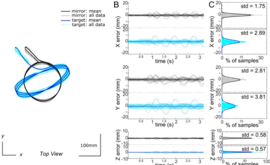
To assess the accuracy of generating target movements and their 3D reconstructions using the CoreXY system, we studied the positioning error of a circular and an ellipsoid trajectory across eleven trials each. Both trajectories covered a large section in the horizontal plane of the experimental arena (Figs. 3A and 4A). First, an initialization phase brought the cart to a reference point close to one of the walls defined by electromagnetic stops. Then the cart moved away from the wall and reached its cruising speed. The desired trajectory can start, here three successive circles on each of the 11 tries. The mirror and target posi-tions were measured every 10 ms, where the mirror is considered to be placed in the centre of the cart. For the circular trajectory, we obtained standard deviations (SD) of the mirror position along the x, y and z axes as small as 2.07, 3.34 and 0.76 mm, respectively (Fig. 3C), and SD = 4.23, 5.65 and 0.97 mm along the three axes for the target posi-tion. During this circular trajectory, the mirror and the target travelled 1.7 and 2.5 m, respectively. On the ellipsoid trajectory the mirror is still moving on a circular path, but the target generates an elliptical movement along which it changes its velocity profile. The standard deviations based on data across 11 trails were even smaller than those for the circular trajectory. The highest SD (for the y-axis) was below
3 mm for the mirror and below 4 mm for the target (Fig. 4).
2.3. Spatial resolution of the cameras
The spatial resolution of any object in the recorded video footage depends on the pixel resolution the cameras used in relation to the distance-dependant size of the objects. CAM1 and CAM2 recorded images at a resolution of 640 × 480 pixel (see Section2.1.2). The focus of the cameras was adjusted to the centre of the arena, about 50 cm away from the cameras. At this position 1 pixel on the cameras’ CCD sensor corresponds to 0.73 × 0.97 mm along the spatial x- and y-di-mension (assuming no image deformation). This means that the smal-lest silhouette of thefly with a diameter of 4 mm, i.e. when the fly is directly facing the camera (without considering wings or legs), will be mapped onto about 17 pixels of the CCD sensor. This number of pixel proved to be sufficient to extract the animal's body ellipse using custom-made image processing tools.
To assess the performance of the system we designed a test module that was attached to the cart of our experimental setup. It consisted of a rotating shaft to which a rod was attached at the end of which a dead specimen (male Lucilia Sericata) was suspended (Fig. 5A).
The longitudinal body axis of the specimen was aligned with the centre (optical axis) of a mirror implemented at the lower end of the shaft. The distance between the mirror and the specimen (Ra) was 45 mm. Compared to life maleflies which measure about 10 mm along their longitudinal body axis, the dead specimen was smaller with a length of about 7.5 mm – probably due to desiccation. The rotating shaft holding the mirror was moved on a circular path (Fig. 5B black trajectory) while itself turning at 1000°/s. As a result, the dead spe-cimen did temporarily move at higher speeds than described for the mirror and target of the CoreXY system in Section1, more closely ap-proximating natural chasingflights (Fig. 5C). These compound trajec-tory cover a large range of variations offly and mirror orientations within a large part of the arena. The trajectories were recorded two times with both cameras at 190 frames per second (N = 1191 frames). We assessed the spatial resolution of our method by comparing the known distance between the mirror and thefly (45 mm) and the fly length (7.5 mm) with the values produced by the 3D reconstruction system. The a associated with PT(θa, φa, Ra) denotes the target bearing angle, or absolute line which connects the center of mass of thefly Q, and the center of mass of the target T. The b associated with OP(θb, φb, Rb) denotes the pursuer heading angle, or longitudinal body axis of the Pursuer (b for body), that connects the top of the head H to the tip of the abdomen O (seeFig. 5E). The system returned a meanfly-mirror distance Ra of 45 ± 5 mm SD and a mean fly length Rb of 7.5 ± 1 mm SD (seeFig. 5D).
Fig. 2. Chasing arena. Picture of the chasing arena from outside (A) and from inside (B) with a close-up view on the target placed at the tip of a rod that is attached to an actuated rotating shaft. The latter supports both the rod and the small mirror enabling them to rotate simultaneously.
As the longitudinal body axis of thefly was aligned with the spe-cimen-mirror line, we could determine the azimuth and elevation error angles between those two axes. We found a mean azimuth error of −3 ± 6° SD and a mean elevation error of −3 ± 3° SD. Making the hypothesis that the head and body arefixed, when reconstructing the field of view of the pursuer, those errors of body orientation will re-present an error of a couple of ommatidia for Lucilia Sericata.
3. Analysing 3D chasingflights
We used the novel setup to record chasing flights in blowflies (Lucilia Sericata). Pupae were purchased from an animal supplier (BioFlyTech) in Spain. For further work, we have established a breeding. Maleflies aged between 5 and 12 days were placed in the arena. They were exposed to a 12:12 h light:dark cycle with a lumi-nance of about 2000 cd m−2at a temperature between 20 and 25 °C. They stayed in the arena without engaging in an experiment for one day to get used to their new environment. Chasing flights were recorded around noon, during their peak activity phase. We used a black sphere of 8 mm diameter as a target.
3.1. Parameters describing strategies of catching targets
Animals have developed different strategies to catch prey or con-specifics. Even in flying insect species of similar size, depending on the specific task, the strategies may be as different as chasing or inter-cepting a given target (Pal, 2015; Gonzalez-Bellido et al., 2016). To distinguish between those strategies quantitatively requires the identi-fication and characterization of relevant parameters that determine the given flight behavior. In this section we will describe some of the parameters our experimental setup allows us to capture. We recorded freefight pursuits at a rate of 190 fps, corresponding to a time resolu-tion of 5.3 ms. The 2-dimensionally tracked posiresolu-tions of the target and the pursuer were computed with the DLT coefficients (on how to get those coefficients see Section2.1.2andHedrick, 2008) to reconstruct their 3D positions. When presenting the flies with a circular target trajectory we observed essentially the same behaviour as Boeddeker et al. (2003), who distinguished between‘capture-’ and ‘pursuit-flights’. In the former case, the pursuingfly soon captures the target while in the latter case the animal pursues the target moving on a circular trajectory for at least one circle (about 650 ms with a target moving at 1 m/s).
Fig. 3. Precision of a circular target trajectory across 11 trials. (A) Superimposed circular trajectories reconstructed by the calibrated stereo vision system. Successive loops do not overlap perfectly: this is partly due to me-chanical imprecision in moving the target, and party due to imprecision in the video tracking. (B) Superimposed plots of the x-, y-, and z-components of the positional error observed for the target (blue) and the mirror (black) over time. The mirror positions are given in grey with the std window, and the target positions in blue graphs. (C): Distribution of errors + Gaussianfits for the mirror and the target po-sitions along the x-, y- and z-axes. (std = stan-dard deviation).
Fig. 4. Precision of a ellipsoidal target trajec-tory across 11 trials. (A) Superimposed circular trajectories reconstructed by the calibrated stereo vision system. (B) Superimposed plots of the x, y, and z components of the positional error observed for the target and the mirror over time. (C) Distribution of errors + Gaussian fits. SeeFig. 3for details.
Fig. 5. Validation of the 3D trajectory reconstruction method. (A) A dead specimen was attached to a transparent off-axis rod and aligned with a mirror at a distance of 45 mm. Thefly's length along its longitudinal body axis was about 7.5 mm. (B) top view of the measured trajectory of the mirror (black) and the specimen (red). Black scale bars refers to x- and y-axis of the arena. (C) Mirror and specimen velocities of the trajectories presented in (B) plotted as a function of time. The mirror moves at a constant speed of 0.7 m/s (black trace). The specimen is moved around the mirror with an angular velocity of almost 1000°/s and presents a linear velocity range between zero and 1.4 m/s (red trace). (D) Measured distances. Top: Distance Fly-Mirror,Ra: median = 44.18 mm; mean = 45.14 ± 5.26 mm SD. Bottom: Fly lengthRb: median = 7.23 mm; mean = 7.53 ± 1.24 mm SD. (E) Tracked points of interest. Left: The line OH describes the specimen's orientation defined by the tip of the abdomen,O, and the front of the head H, given in spherical coordinates (θb, φb, Rb, b for body). Right: The line PT, connects the center of mass P of the specimen (P for pursuer) with the center of massT of the target, in spherical coordinates PT(θa, φa, Ra). (F) Angular resolution. Errors were obtained by calculating the difference between the vectors PT and OH shown in (E) (comp A − comp B). Left: Azimuth error (θa − θb): median = −2.89°; mean = −3.07 ± 5.88°. Elevation error (φa − φb): median = −2.89°; mean = 3.32 ± 3.19°. Medians, means and SDs based on N = 1191 frames.
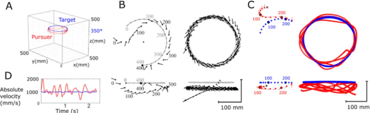
Fig. 6. Preliminary results: Example of fast capture and long pursuit characterization. (A) Reconstruction of a male blowfly chasing a dummy target. (B) Left: Reconstructed 3D trajectory of afly (black markers) capturing the target (grey markers) viewed from on top and from the side. Filled circles and lines indicate the fly's centroid position and body orientation, respectively. The numbers denote time stamps during the chasingflight spaced at 100 ms. Right: Chasing flight without target capture. Results shown in left and right subplot copied from Boeddeker et al. 2003. (C) Pursuit of the target during a similar experiment as shown in (B), performed in our chasing arena. Left: Reconstruction of afly (red markers) capturing the target (blue markers) during a fast capture (250 ms). For sake of clarity the positions are placed every 20 ms, and except for colors, the caption is the same as in (B). Right: Reconstruction of a long pursuit without target capture (data from subfigure A). Each dot indicates the centre of mass of the target (blue) and thefly (red) plotted every 5 ms. For sake of clarity the body orientation and time stamps are not presented here. (D) Absolute velocity of the target and thefly during pursuit seen in subfigure (A and C, Right). The target speed is centred around 1 m/s whereas the pursuer's speed reached peak values of up to 2 m/s.
Examples of bothflight type trajectories reported byBoeddeker et al. (2003) are shown in Fig. 6B. For comparisonFig. 6C shows similar flight trajectories studied with our novel setup. In both pursuits the fly chases the target moving along a circular path at a constant speed of 1 m/s. The absolute velocity profiles of the target and the long pursuit flight are shown inFig. 6D, where we can see that thefly velocity varies a lot, and it reaches a maximum of 2 m/s. The 3D reconstruction of the sequences provides valuable information about the fly's strategy to capture the target. In both types of chasingflights (fast capture or long pursuit see Fig. 6C), the flight path of the fly suggests that it is not guided by an interception strategy. Instead, thefly closely follows the circular trajectory of the target. To investigate the behaviour in more detail we presented ourflies with more complex target trajectories.
Fig. 7shows a fast capture when the target follows a type of tra-jectory different from a circle. We called this specific tratra-jectory the ‘spinning top’. It consists of a simple translation along the y-axis
combined with a rotation of the target around the z-axis. The rod, the target is attached to, rotates at 600°/s, but is also subject to translation due to the movement of the cart. As a result, the angular rotation of the target varies between 380 and 1340°/s. Its linear speed component (in the horizontal plane) varies between 450 and 1060 mm/s with a mean of 700 mm/s. Along this trajectory, the target changes both direction and velocity, which makes it closer to the kinematics of the female flight. In our pilot study we focused only on capture chases, i.e. when the pursuer successfully catches the target in mid-air.Fig. 7shows some of the results, in addition to the 3D reconstruction of one chasingflight in the experimental arena together with a top and side view of the entire sequence. This capture sequence occurs in about half a second. The chaser was hovering close to a wall oriented opposite to the target when he detected it.
The start of a pursuit is initiated when thefly detects the target. It is easily identified in the recorded image sequences as the pursuer
Fig. 7. Preliminary results: Analysis of dynamics in a capture. (A) Reconstruction of a chasingflight after a target moving along a ‘spinning top trajectory’. Bigger points mark positions reached after 100 ms time intervals. The target is moving in the horizontal plane indicated by the blue lines (350*). Arrows show the direction of the target and the pursuer at the beginning of the sequence. (B) Top and side view of the chasingflight shown in (A). Head and tip of the abdomen of the pursuer are represented by differently coloured markers. The high degree of overlap of the markers demonstrates the robustness of the method. (C) Relative position of the pursuer when initiating the pursuit (top view). Two types of target trajectories are presented: open circles for the 10 circular trajectories, andfilled circles for the 8 spinning top trajectories (target in blue). (D) Altitude change of the pursuer before target capture. Dots on the left give the detection altitude (mm) of the pursuer for each chase. (E) Top view of the chases. Note the distinct target trajectories, Central Circle, and Spinning Top on the right side of the circles. Positions where thefly initiates the pursuit are shown in whitefilled dots for Circle Trajectories, and black filled dots for spinning top trajectories. The black rectangle represents the experimental surface. (F) Change of the Distance To Target (DTT) before the capture. Dots represent the detection DTT of each pursuit. Opened markers for circular trajectories, andfilled markers for spinning trajectories. (G) Definition of the measured angles. From the top view only the azimuth component of the error angles is available. Left: The error angleθe1 or Target Heading angle is defined by the angle made between the Line of Sight (LoS azimuth: θa, or target bearing angle) and the longitudinal body axis (LoB for Line of Body, azimuth:θb, also Yaw of the fly). Right: Part of a pursuit sequence. Three consecutive horizontal positions of the Target (T) and of the Pursuer (P) are represented by their center of mass. The Line of Flight of the pursuer at time t is the line joining previous and next positions (LoF azimuth:θf). This line plotted on the point P(t) is similar to the tangent of the trajectory on this point. The Error angle θe2 describes the Target relative bearing. It is the angle made by the Line of Flight of the pursuer and the Line of Sight. (H) Boxplot of the two components (azimuthθ and elevation φ) of the two error angles for the 17 captures presented above. These two error angles are significantly different on both planes (Ttest, p(az) = 9E-17, p(el) = 2E-100, see ***, N = 1104).
visual input to support tightly controlled pursuitflights. This requires, as presented above, an orientation of the visual system where the target is projected onto this specialized region of the eye.
We measured the two error angles when presenting to the males the two trajectories described above. Regardless of the trajectories (and so to the angular velocity tested), the two errors are significantly different (two samples t-test: p(θe1, θe2) = 9E-17, p(φe1, φe2) = 2E-97) see
Fig. 7H. This emphasizes the non alignment of LoS and LoB, causes are discussed below.
4. Discussion
We have developed a novel experimental setup that enables us to monitor the 3-dimensional movements of a freelyflying fly chasing a dummy target along an arbitrary 2-dimensional trajectory. The quan-titative analysis of the dummy movements shows that our method en-ables us to generate highly reproducible trajectories across tries. Both target position and the position of a pursuingfly are monitored and reconstructed at high spatial as well as temporal resolution, including the pursuer's body orientation. Those data are instrumental to retrieve the kinematics of the pursuingfly and to study the visual parameters the animal controls during chases.
A system adapted to blowfly and housefly speed. Our setup does not have the capability to generate dummy speeds equivalent to those of the hoverfly Eristalis tenax female, which, according toCollett and Land (1978), was assumed to reach maximum speeds up to 8 m/s. But it can generate maximum dummy velocities of 3 m/s which is adequate to study slowerfly species such as blowflies and houseflies, where females fly at mean speeds of 1.2 and 0.65 m/s, respectively (Ennos, 1989; Land and Collett, 1974). A target velocity of 3 m/s was the maximum ob-tained when it was mounted on a 15 cm long rod (seeFig. 8B). Amongst Diptera, Eristalis tenax is considered the most agile, responding to a change of the target trajectory in as little as 20 ms. Other Dipteran pursuers have a longer reaction time. Male Fannia, for instance, respond only after 30 ms (Land and Collett, 1974). Time response of the chasing behaviour of Lucilia has not been measured yet. Boeddeker and Egelhaaf (2003), nonetheless, have implemented a model of Lucilia pursuing a target, that assumes a response delay of only 15 ms based on the analysis of the Line of Flight (LoF). Ourflight trajectory acquisition system allows us to detect changes both in LoF and body orientation (LoB) with a temporal resolution limited by the 5.3 ms time interval between two consecutive frames. This acquisition speed is enough to check the values of the model created by Boeddeker and Egelhaaf (2003)which will be presented in an article in preparation.
The body orientation of the pursuer. Infirst experiments on Lucilia we focused on our hypothesis regarding the body orientation of the male fly during pursuit. When considering the pursuer as a ellipsoid body, defined by the position of its center of mass and two angles orientations: absolute yaw and pitch angles, we observed that thefly do not have the same orientation profile when chasing a dummy that executes slow or fast angular moves. We presented to the males two target trajectories, ‘circular’ and ‘spinning top’, that differ in target angular velocity (see
Fig. 7caption for trajectories’ details).
Horizontal plane: body yaw, heading, and side-slips. Over the range of target velocities we tested,flies always aligned their longitudinal body axis (yaw- orientation) with the line of sight (LoS) to keep the image of target projected onto their‘love spot’. But we observed that the hor-izontal component of the LoF is hardly aligned with the LoS at high angular velocities (significant difference between the two angular ve-locities p = 0.002). This difference is likely the result of inertia-based side-slip during fast trajectory changes which, to our knowledge, has not been analysed during chasingflights before. Tested target trajec-tories included only clockwise rotation components. As a result, the values for the angleθe2 relative to LoS and LoF are always larger than those forθe1 relative to LoS and LoB (seeFig. 7H). This difference is probably the consequence of the animal's side-slip component which is changes its body orientation in a saccade-like way followed by an
ac-celeration phase. In Fig. 7C the position of the fly at the point in time before the body saccade is plotted relative to the target position. The data suggests that pursuit flights are initiated independently of the current position of the fly.
An important parameter for the analysis of the pursuit flight tra-jectory is the Distance To Target (DTT) presented in Fig. 7F. The change of this parameter can give valuable information about the strategy if it is not linear (Wardill et al., 2017; Kane et al., 2015). This change of this parameter along the z-axis (or altitude), which has rarely been taken into account in previous studies, is highly relevant when it comes to a 3D model of aerial pursuit strategies (see Fig. 7D and F). It is also re-quired for estimating forces (here lift) the fly produces when ap-proaching the target.
3.2. Parameters describing the orientation of the fly during pursuit flights The knowledge of velocity vector during a flight trajectory alone does not necessarily allow us to reconstruct the region of the eyes onto which the image of a target is projected because its direction may not be aligned with body orientation of the animal in case of drift or sideslip (Wagner, 1986b). Thus, to characterize pursuit strategies, we will take care on analysing three lines and the angles they form with the re-ference frame.
The longitudinal body axis of the fly, here called Line of Body (LoB), defines the body orientation (see OH in Fig. 5E, θb Fig. 5E and Fig. 7G). Yaw and Pitch are the two angles that define this line. The Line of Sight (LoS), is the line connecting the centre of mass of the fly with the target (see PT in Fig. 5E, θa Fig. 5E and Fig. 7G), it is defined by the target bearing angle. The direction of travel, or Line of Flight (LoF) is defined by the line connecting the previous and the next positions in time of the fly. It is same as the tangential line of the flight trajectory, also referred to heading direction in literature.
It is important to note that in the context of aerial pursuit, the term “Error Angle” that is often found in the literature, may have different meanings. Here we propose the analysis of two error angles, defined by the three lines presented above. The error angle 1 (e1), is the angle formed by the LoS and the LoB. This angle characterizes the alignment of the body with the target position. In the case that the head is fixed to the body, it is directly linked to the position of the target on the fly's retina. The second parameter here called error angle 2 (e2), is the angle formed by the LoS and the LoF as defined by Land and Collett (1974). This angle gives information about the kinematics of the pursuit's strategy (Fajen and Warren, 2007; Gonzalez-Bellido et al., 2016).
In this account we define the orientation of the fly by its yaw-, pitch-and roll- angles. This means that in an absolute coordinate system, angles which are relative to the orientation of the fly will have an azimuth and an elevation component. The method proposed here al-lows us to separately extract and analyse those components along the entire pursuit flight sequence. The comparison between the two types of trajectories (circle and spinning top) suggest that the target speed does not affect the azimuth of error angle 1 (two samples t-test: p (θe1) = 0.46). The Line of the Body stays aligned to the Line of Sight, so the pursuer holds the target in the central part of its visual field, in the ‘love spot’ position.
In predatory species or in species where males catch female on the wing (Land and Nilsson, 2012), we observe a functional regionalization of the compound eye. In the former case, the animals are endowed with a small area in the frontal eye around the eye equator and above that features exceptionally high spatial resolution (van Hateren et al., 1989; Wardill et al., 2017; Sherk, 1978). Similar functional adaptation in the context of mating have been reported in various fly species including hoverflies and blowflies (Collett and Land, 1975; Land and Eckert, 1985), supported by high performance photoreceptors (Burton and Laughlin, 2003; Hornstein et al., 2000). In either case, only a specia-lized high resolution area of the eye provides sufficiently fast and robust
always directed outwards with respect to its turning radius. Had we applied symmetrical clockwise and counter-clockwise rotation compo-nents to the dummy trajectories, we could have easily missed the dif-ference as positive and negative values ofθe2 would have cancelled out each other. To confirm our observation in future experiments we will generate dummy movements with symmetrical rotation components, e.g.‘figure-8-trajectories’, analysing the un-signed angular data sepa-rately for clockwise and counter-clockwise rotation components.
Body pitch and the altitude changes. We did not observe significant differences p = 0.09 of the angle φe2 (elevation angle formed between LoS and LoF) when target moved at slow or fast angular velocity. This suggests the absence of vertical-slips in the sagittal plane, in other words there is no inertia dependant offset in the x–z plane. To further investigation adjustment of the elevation component of the LoF, we would have to introduce changes in the z-position of the moving target, which should in principle be possible by means of slight alterations of our current setup.
Head-bodyfixation. Aerial pursuits in blowflies usually occur in less than 500 ms, from detection of the target to capture. During the chase, the malefly reaches maximum speeds of 2 m/s. Even at such high speed vision can provide the chaser fast and accurate information about the position of the target. Such challenging chasing flights have been modelled following two different approaches: kinematic models, and sensory-motor models. The large variety of target trajectories our new setup enables us to generate, will help to develop more general models of the pursuit, which include additional relevant parameters such as absolute andfly-centred orientation of the body, side-slips, and retinal position of the target. Initially, however, we will have to make an as-sumption that was made in previous modelling approaches, e.g. by
Boeddeker et al. (2003): the head of thefly is aligned with and attached to the thorax, excluding any relative head-body movements. This con-straint may be overcome once our micro-endoscope module (MEM)
provides us with quantitative data on head-body rotations (see below). In the following we will discuss current modelling approaches on chasingflights.
Kinematic models of the chasingfly. They allow the analysis of capture strategies (Pal, 2015) as a balance between speed and manoeuvrability (Howland, 1974). They also characterize the pursuer'sflight envelope. Once we designed the pursuer's object, here an ellipsoid defined by its centre of mass and its yaw- and pitch- angles, its envelop can be defined as the possible combination of translational and rotational movement components. Our method enables us to measure 3D target and pursuer positions with a maximum error of 5 mm. This position error is due to distortions caused by the camera optics, increased with increasing ec-centricity and distance from the cameras, but less than 2 mm when the fly in the center of the arena. The chasing fly's yaw- and pitch- body orientation are measured with an error smaller than 6°, sampled every 5.3 ms. This makes the method suitable for building acceptable kine-matic model of the pursuit. In comparison, the latest kinekine-matic model of the blowfly pursuer (Boeddeker and Egelhaaf, 2003) was based on pursuits recorded in a cubicflight arena with 30 cm size, where the target moved along a circular path at constant speed. In this study, 3D-reconstruction system offered a spatial resolution of ± 1.5 mm and temporal resolution of 20 ms, which was same order of magnitude that the 15 ms delay to change the heading angle. In addition, body pitch-and roll- of thefly could not be extracted.
Banked turns in insectflights. Previous studies suggested that fruit flies are able to change their heading direction without banking by generating torque about their yaw- axis (Götz, 1964; Hedrick et al., 2009; Bergou et al., 2010). More recent studies, however, have shown that during fast escape manoeuvres they do perform banked turns (Muijres et al., 2014; Karasek et al., 2018). For a blowfly with a sig-nificant inertia operating at Reynolds number around 600 (Buckholz, 1981), banked turns are common during body saccade (Schilstra and
Fig. 8. Embedded pictures of the target and the pursuer. (A) Three pictures taken from the MicroCamera placed originally in the vertical tube of the moving cart (see
Fig. 1C). Three sizes of targets have been tested to evaluate thefield of view of the rotating mirror. The micro-endoscope module (MEM) allows us to detect the pursuer's legs, wings and eyes in the video footage. (B) Last 63 ms of the target capture presented inFig. 7A, monitored with the MEM as described inFig. 1C. The pursuer approaches the target before thefinal catch. A small flag was waxed onto the pursuer's dorsal thorax indicating its dorso-ventral body axis. Tracking the tip of theflag (red dot) enables the reconstruction of the external body roll- coordinate. Reconstruction of the full body attitude (yaw-, pitch- and roll-) is possible at high temporal resolution (5.3 ms).
keeps the target in the camera'sfield of view (Fig. 8A). Ourfirst results validate the functional design of the module which enables us to sta-bilize a frontal view of the chasingfly even during a curved trajectory of the dummy. They also confirmed qualitative observation of banked turns during those pursuits, where the body roll- angle can assume values above 90°. The initial test version of the module, however, did not have sufficient temporal resolution to support a meaningful quan-titative analysis of the video footage.
The micro-endoscope method (MEM). The second version of the module was based on a microendoscope technique, proposed byPierce et al. (2011). This technique offers a high temporal resolution
config-uration that can be used to monitor the pursuer's body orientation until when the pursuer catches the dummy. We performedfirst tests using a 50,000 pixels opticalfibre bundle (MyriadFiber) combined with a 1 mm Grin lens (infinity focal depth, and visual field of 60°, GrinTech). Images were transmitted via the opticalfibre bundle to a CCD camera, which was equipped with a microscope objective focused on the end of thefibre bundle. The CCD camera was synchronized with the other 2 high speed cameras which monitored the position of the dummy and chasingfly at 190 fps.Fig. 8B shows the frames obtained during the final phase of a capture flight. A flag attached to the dorsal part of the thorax of thefly was tracked relative to the position of the legs to compute the roll angle of thefly. The spatial resolution with the 50,000 pixelsfibre bundle was not high enough to extract confidently the body angle in all pursuits, but in the latest version we are implementing a 100,000 pixelsfibre bundle which will give enough spatial resolution for further investigations.
Head-body rotations. Movements of the head relative to the body have minimum impact on the general trajectory of thefly when con-sidering a kinematic model of the pursuit. However, as the movement of the head relative to the body significantly affects the retinal position of the target, it plays a major role when the pursuit is modelled from a sensory-motor perspective. The general assumption is that body roll is compensated by head rotations (Hardcastle and Krapp, 2016). This still needs experimental support in connection with chasing flights. The head of thefly in the video frame shown inFig. 8A appears not to be in a horizontal orientation. Even if the gaze was stabilized around the roll axis, thefly might as well use head yaw and head pitch to keep the image of the target projected onto the love spot. Head's yaw- and pitch-also need to be assessed for similar reasons. The MEM module will enable us to monitor head orientation which will help us to analyse the visual parameters thatflies control during chasing flights.
External perturbations. Chasing behaviour inflies occurs in many different natural environments such as bushes, empty fields, forests and even indoor below chandeliers (Land and Collett, 1974). The presented setup is a good support to investigate how the pursuit course is affected by external perturbations such as obstacles or wind.
Conflict of interest None declared.
Author contribution
L.V.-P. designed the experimental setup and wrote the paper. H.G.-K. and S.V. provided administrative and scientific support, they verified the results and corrected the paper. S.V. proposed the principle based on a micro-camera and a rotating mirror to record the target point of view. All authors read and commented on the manuscript.
Acknowledgments
We would like to thank Julien Diperi, and Marc Boyron for their technical support. Roman Goulard, Ben Hardcastle and Jiaqi Huang for fruitful discussions. This work was supported by DGA through the co-supervised Fr UK PhD program. S.V. acknowledges support from the
Hateren, 1999). Whether or not blowflies perform banked turns when engaging on chasing flights has not yet been systematically studied, but our first observations suggest that they do.
Body pitch, forward speed, and the changes of heading. We observed that the elevation coordinate of the error angle between LoS and LoB (see φe1 in Fig. 7G) is significantly different (p = 0.01) when the target moves with slow or high angular velocity. This can be explained by a two steps relation. First, the linear relation between the forward speed and the absolute pitch- angle as described in blowfly bySchilstra and Hateren (1999), then if we consider the pursuer as a fixed-wing aircraft, the banking angle formula ˙θp =g/Va× tan(Ω) (Beard and McLain,
2012) gives us that the change of heading (θ˙p ) is linked to the forward
speed (Va), with Ω the banking angle and g the gravitational field strength. This testify the relation we found between the absolute body pitch angle and the change of heading (linked itself to the angular ve-locity of the target), and so, the importance of banked turns in chasing. To develop a realistic dynamic model of chasing flights taking into account the banked turns, the fly's body roll- component has to be in-cluded.
Banking angle and angle. Nonetheless, banking angle or roll-angle has to be clarified. Assuming the flight kinematics of the a blowfly are similar to those of a fixed-wing aircraft, the most efficient way of changing flight direction would be the performance of coordinated turns (McClamroch, 2011) such as honeybees when loitering around the beehive (Mahadeeswara and Srinivasan, 2018). If xA, yA and zA are the axes of a fly- or aircraft-fixed coordinate system, the body roll- angle is defined as the rotation angle around xA (or the LoB axis). The banking angle is defined as the angle between the aircraft fixed yA and the horizontal plane, based on a rotation around the LoF. Thus, unlike the body roll- angle which is related to steady fly body orientation, the banking angle is linked to the fly's velocity vector. In coordinated flight, the side-slip angle is zero, so without a side-slip component the LoF is aligned with the LoB and the body roll- angle is equal to the banking angle. But in the presence of side-slips, the body roll- and banking angle are different. This will be taken into account when developing more general models of the pursuit (article in preparation).
Sensory-motor models. As mentioned earlier, an alternative to a ki-nematics-based model would be modelling the sensory-motor control loop of the fly during chasing flight. In the latter approach, visual in-formation forms the sensory input to the system which is transformed into motor outputs controlling the fly's position and orientation. Gaze stabilization plays here a major role. To stabilize the visual input, in other words to keep the target in a fixed position of the retina, would be massively simplified with compensatory head roll (Hengstenberg, 1991; Hardcastle and Krapp, 2016). In the next paragraph we will present the additional module that will allow to quantify head-body rotations.
Close-up approach visualization module. Even more advanced real time video tracking systems such as the one developed by Straw et al. (2011) did not capture the roll orientation of the animal. Smaller arena can be an option, because of smaller distances and therefore higher spatial resolution in combination with focal depth of the cameras such as in Muijres et al. (2014), but it would be inadequate to study pursuit strategies in bigger species which require more space to perform chasing flights. Other techniques have been developed to estimate body roll during free cruising flight (Ristroph et al., 2009), in tethered flies (Tammero and Dickinson, 2002), or in semi-tethered flies (Schilstra and
Van Hateren, 1998) but never during aerial pursuits in free flight. We have designed an addition functional module for our flight arena that will allow us to monitor the body orientation of the fly while chasing the target. We recorded chasing sequences using two configurations of this additional optical module (Fig. 1C).
The micro-camera and its low temporal resolution. Our video footage so far allowed us to identify the legs and some details of the ap-proaching fly's head. The first version of this module consisted of a micro-camera (NanEye from Awaiba) facing a rotating mirror that
Princeton University Press”. Princeton University, The Trustees of Princeton University.press.princeton.edu/titles/9632.html.
Bergou, A.J., Ristroph, L., Guckenheimer, J., Cohen, I., Wang, Z.J., 2010. Fruitflies modulate passive wing pitching to generate in-flight turns. Phys. Rev. Lett. 104 (14).
https://doi.org/10.1103/physrevlett.104.148101.
Boeddeker, N., Egelhaaf, M., 2003. Steering a virtual blowfly: simulation of visual pursuit, Proceedings. Proc. R. Soc. B: Biol. Sci. 270 (1527), 1971–1978.
Boeddeker, N., Kern, R., Egelhaaf, M., 2003. Chasing a dummy target: smooth pursuit and velocity control in male blowflies, Proceedings. Proc. R. Soc. B: Biol. Sci. 270 (1513), 393–399.
Buckholz, R.H., 1981. Measurements of unsteady periodic forces generated by the blowfly flying in a wind tunnel. J. Exp. Biol. 90, 163–173.
Burton, B.G., Laughlin, S.B., 2003. Neural images of pursuit targets in the photoreceptor arrays of male and female houseflies Musca domestica. J. Exp. Biol. 206 (22), 3963–3977.
Collett, T.S., Land, M.F., 1975. Visual control offlight behaviour in the hoverfly Syritta pipiens L. J. Compar. Physiol. A 99 (1), 1–66.
Collett, T.S., Land, M.F., 1978. How hoverflies compute interception courses. J. Compar. Physiol. A 125 (3), 191–204.
Egelhaaf, M., Borst, A., 1993. A look into the cockpit of thefly: visual orientation, al-gorithms, and identified neurons. J. Neurosci. 13 (11), 4563–4574.
Ennos, B.Y.A.R., 1989. The kinematics and aerodynamics of the freeflight of some dip-tera. J. Exp. Biol. 85, 49–85.
Fajen, B.R., Warren, W.H., 2007. Behavioral dynamics of intercepting a moving target. Experimental Brain Research.
Gonzalez-Bellido, P.T., Fabian, S.T., Nordström, K., 2016. Target detection in insects: optical, neural and behavioral optimizations. Curr. Opin. Neurobiol. 41, 122–128.
Götz, K.G., 1964. 0ptomotorische Untersuchung des visuellen Systems einiger Augenmutanten der Fruehtfliege Drosophila. Kybernetik 2 (2), 77–92.
Hardcastle, B.J., Krapp, H.G., 2016. Evolution of biological image stabilization. Curr. Biol. 26 (20), R1010–R1021.
Harris, W.A., Stark, W.S., Walker, J.A., 1976. Genetic dissection of the photoreceptor system in the compound eye of Drosophila melanogaster. J. Physiol. 256, 415–439.
Hedrick, T.L., 2008. Software techniques for two- and three-dimensional kinematic measurements of biological and biomimetic systems. Bioinspir. Biomim. 3 (3), 034001.
Hedrick, T.L., Cheng, B., Deng, X., 2009. Wingbeat time and the scaling of passive ro-tational damping inflapping flight. Science 324 (5924), 252–255.
Hengstenberg, R., 1991. Gaze control in the blowfly Calliphora: a multisensory, two-stage integration process. Semin. Neurosci. 3 (1), 19–29.
Hornstein, E.P., O’Carroll, D.C., Anderson, J.C., Laughlin, S.B., 2000. Sexual dimorphism matches photoreceptor performance to behavioural requirements. Proc. R. Soc. B: Biol. Sci. 267 (1457), 2111–2117.
Howland, H.C., 1974. Optimal strategies for predator avoidance: the relative importance of speed and manoeuvrability. J. Theor. Biol. 47 (2), 333–350.
Mayer, I.E., 2012. corexy.com.
Kane, S.A., Fulton, A.H., Rosenthal, L.J., 2015. When hawks attack: animal-borne video studies of goshawk pursuit and prey-evasion strategies. J. Exp. Biol. 218 (Pt 2), 212–222.
Karasek, M., Muijres, F.T., Wagter, C.D., Remes, B.D.W., de Croon, G.C.H.E., 2018. A tailless aerial roboticflapper reveals that flies use torque coupling in rapid banked
turns. Science 2 (September), 1089–1094.
Land, M.F., 1993. The visual control of courtship behaviour in thefly Poecilobothrus no-bilitatus. J. Compar. Physiol. A 173 (5), 595–603.
Land, M.F., Collett, T.S., 1974. Chasing behaviour of houseflies (Fannia canicularis). J. Compar. Physiol. 89 (4), 331–357.
Land, M.F., Eckert, H., 1985. Maps of the acute zones offly eyes. J. Compar. Physiol. A 156 (4), 525–538.
Land, M.F., Nilsson, D.-E., 2012. Animal Eyes, Volume 2.
Mahadeeswara, M.Y., Srinivasan, M.V., 2018. Coordinated Turning Behaviour of Loitering Honeybees. Sci. Rep. 8 (1), 1–14.
McClamroch, N.H., 2011. Steady Aircraft Flight and Performance. Princeton University Press.
Menzel, R., Backhaus, W., 1991. Colour vision in insects. In: Gouras, P. (Ed.), Vision and Visual Dysfunction. The Perception of Colour. MacMillan, London, pp. 262–288.
Mischiati, M., Lin, H.-T., Herold, P., Imler, E., Olberg, R., Leonardo, A., 2015. Internal models direct dragonfly interception steering. Nature 517 (7534), 333–338.
Muijres, F.T., Elzinga, M.J., Melis, J.M., Dickinson, M.H., 2014. Flies evade looming targets by executing rapid visually directed banked turns. Science 344 (4), 172–177.
Olberg, R.M., Seaman, R.C., Coats, M.I., Henry, A.F., 2007. Eye movements and target fixation during dragonfly prey-interception flights. J. Compar. Physiol. A: Neuroethol. Sensory Neural Behav. Physiol. 193 (7), 685–693.
Olberg, R.M., Worthington, A.H., Venator, K.R., 2000. Prey pursuit and interception in dragonflies. J. Compar. Physiol. A: Sensory Neural Behav. Physiol. 186 (2), 155–162.
Pal, S., 2015. Dynamics of aerial target pursuit. Eur. Phys. J. Spec. Top. 224 (17-18), 3295–3309.
Pierce, M., Yu, D., Richards-Kortum, R., 2011. High-resolutionfiber-optic microendo-scopy for in situ cellular imaging. J. Vis. Exp. 47, e2306.
Portelli, G., Ruffier, F., Franceschini, N., 2010. Honeybees change their height to restore their opticflow. J. Compar. Physiol. A: Neuroethol. Sensory Neural Behav. Physiol. 196 (4), 307–313.
Ristroph, L., Berman, G.J., Bergou, A.J., Wang, Z.J., Cohen, I., 2009. Automated hull reconstruction motion tracking (HRMT) applied to sideways maneuvers of free-flying insects. J. Exp. Biol. 212, 1324–1335.
Schilstra, C., Hateren, J., 1999. Blowfly flight and optic flow. I. Thorax kinematics and flight dynamics. J. Exp. Biol. 202 (11), 1481–1490.
Schilstra, C., Van Hateren, J.H., 1998. Using miniature sensor coils for simultaneous measurement of orientation and position of small, fast-moving animals. J. Neurosci. Methods 83 (2), 125–131.
Sherk, T.E., 1978. Development of the compound eyes of dragonflies (odonata). III. Adult compound eyes. J. Exp. Zool. 203 (1), 61–79.
Sollmann, K.S., Jouaneh, M.K., Lavender, D., 2010. Dynamic modeling of a two-axis, parallel, H-frame-type XY positioning system. IEEE/ASME Trans. Mechatron. 15 (2), 280–290.
Straw, A.D., Branson, K., Neumann, T.R., Dickinson, M.H., 2011. Multi-camera real-time three-dimensional tracking of multipleflying animals. J. R. Soc. Interface 8 (56), 395–409.
Tammero, L.F., Dickinson, M.H., 2002. Collision-avoidance and landing responses are mediated by separate pathways in the fruitfly, Drosophila melanogaster. J. Exp. Biol. 205 (Pt 18), 2785–2798.
van Hateren, J.H., Hardie, R.C., Rudolph, A., Laughlin, S.B., Stavenga, D.G., 1989. The bright zone, a specialized dorsal eye region in the male blowfly Chrysomyia mega-cephala. J. Compar. Physiol. A 164 (3), 297–308.
Wagner, H., 1986a. Flight performance and visual control offlight of the free-flying housefly (Musca domestica L.). II. Pursuit of targets. Proc. Trans. R. Soc. B: Biol. Sci. 312 (1158), 527–551.
Wagner, H., 1986b. Flight performance and visual control offlight of the free-flying housefly (Musca Domestica L.). III. Interactions between angular movement induced by wide- and smallfield stimuli. Proc. Trans. R. Soc. B: Biol. Sci. 312 (1158), 581–595.
Wardill, T.J., Fabian, S.T., Pettigrew, A.C., Stavenga, D.G., Nordström, K., Gonzalez-Bellido, P.T., 2017. A novel interception strategy in a miniature robberfly with ex-treme visual acuity. Curr. Biol. 27 (6), 854–859.
Wardill, T.J., Knowles, K., Barlow, L., Tapia, G., Nordström, K., Olberg, R.M., Gonzalez-Bellido, P.T., 2015. The killerfly hunger games: target size and speed predict decision to pursuit. Brain Behav. Evol. 86 (October), 28–37.
Wehrhahn, C., 1979. Sex-specific differences in the chasing behaviour of houseflies (Musca). Biol. Cybernet. 32 (4), 239–241.
Wehrhahn, C., Poggio, T., Bülthoff, H., 1982. Tracking and chasing in houseflies (Musca) – an analysis of 3-D flight trajectories. Biol. Cybernet. 45 (2), 123–130.
Zeil, J., 1986. The territorialflight of male houseflies (Fannia canicularis L.). Behav. Ecol. Sociobiol. 19 (3), 213–219.
Centre National de la Recherche Scientifique (CNRS), Aix-Marseille Universite and the Agence Nationale de la Recherche (ANR) [with the EVA project (Autonomous Flying Entomopter) and the IRIS project (Intelligent Retina for Innovative Sensing) ANR-12-INSE-0009]. Appendix A. Supplementary data
Supplementary data associated with this article can be found, in the online version, at https://doi.org/10.1016/j.jneumeth.2019.04.006. References
Aziz, A., Karara, H., 1971. Direct linear transformation into object space coordinates in close-range photogrammetry. Proc. of the Symposium on Close-Range
Photogrammetry 1–18.