Development of a Coherent Optical Imaging
System for Clinical Dermatology
by
Ahhyun Nam
B.S., Korea Advanced Institute of Science and Technology (2010)
Submitted to the Department of Mechanical Engineering
in partial fulfillment of the requirements for the degree of
Master of Science in Mechanical Engineering
at the
MASSACHUSETTS INSTITUTE OF TECHNOLOGY
June 2012
ARCHIVES
MASSACHUSETTS INSTITUTE OF TECHNOLOGYJUN
28
2012
LIBRARIES
@
Massachusetts Institute of Technology 2012. All rights reserved.
A u th or ...
/
Department of Mechanical Engineering
May 15, 2012
Certified by...
Certified by.
Benjamin J. Vakoc
Assistant Professor of Dermatology
and e
ces and Technology, HMS, MGH
Thesis Supervisor
...
.
.... ...
George Barbastathis
ngapore Research Professor of Optics
and Professor of Mechanical Engineering
Thesis Reader
Accepted by ...
...David E. Hardt
Chairman, Department Committee on Graduate Theses
Development of a Coherent Optical Imaging System for
Clinical Dermatology
by
Ahhyun Nam
Submitted to the Department of Mechanical Engineering on May 15, 2012, in partial fulfillment of the
requirements for the degree of
Master of Science in Mechanical Engineering
Abstract
The abnormal structure of cutaneous capillaries is associated with many skin diseases including skin cancer and port wine stain. Consequently, the demand for an imaging modality that can provide non-invasive visualization of capillary level blood flow is high. The major challenge in such imaging is to achieve high resolution and great flow sensitivity over a sufficient depth. Numerous imaging techniques derived from optical coherence tomography have provided a technical breakthrough and produced promising images of capillary networks of retina and brain tumors. However, these modalities have never been applied in clinical dermatological studies.
This thesis illustrates the process of design and complete construction of an optical frequency domain imaging (OFDI) system for dermal vasculature imaging that can be used in a clinical environment. The system consists of optical hardware, electronics, and a microscope; every part is contained in a portable cart that can be readily carried to a clinic. The optical subsystem includes a wavelength-swept laser source, a fiber optic interferometer with a delay stage and a polarization-sensitive balanced receiver. All power supplies, control drivers and monitoring circuits are integrated and enclosed in a case with a control interface. The microscope is attached to an articulating arm to be positioned as desired while the patient sits at ease.
The system performance is summarized as 10 jm resolution with frame rate of
100 frames per second. Further studies, in collaboration with dermatologists, will
involve imaging the vascular structure of port wine stain lesions and investigating their correlation to laser treatment.
Thesis Supervisor: Benjamin J. Vakoc Title: Assistant Professor of Dermatology
and Health Sciences and Technology, HMS, MGH
Acknowledgments
First of all, I would like to thank my advisor, Professor Benjamin J Vakoc, for his valuable advice and kind patience during my Master's program. I am truly grateful for his insightful guidance in academic works as well as for the great encouragement.
I would like to express my gratitude to all Vakoc group members, Nishant Mohan,
Meena Siddiqui, and Ellen Zhang for helpful discussion and encouragement during my hard moments. I also am very grateful to Ashley Flibotte for her excellent ad-ministrative assistance.
I also wish to thank Professor William Wangyuhl Oh at KAIST, for being a great
mentor to whom I can turn to at any times without having to prove myself.
It was a great pleasure to take the advanced workshop in writing with Jane
Dun-phy. Her guidance turned the thesis writing itself into a invaluable learning experience
for me.
I want to thank Kwanjeong Educational Foundation of Korea and Wellman Center
for Photomedicine for their generous support for the research.
Close friends have been with me through the highs and lows of the past two years. I am truly grateful for the support and friendship of Jiyoun Christina Chang, Uhirinn Suh, Taedong Yun, and Johnny Hyungruyl Choi. Very special thanks to Sungjune Bae for his sincere care and faithful love which made it possible for me to carry on trying after many downfalls.
Last but not least, my warmest regard and deepest love go to my family. My parents, Kichoon Nam and Haeyoung Hwang, have guided me to my present self with unconditional love. This work couldn't have been possible without their sup-port. I would like to thank my not-so-little brothers, Kyuhyun and Junghyun, for heartwarming encouragement.
Contents
1 Introduction
1.1 Related Works. . . . .
1.2 M otivation. . . . .
1.2.1 Port Wine Stain (PWS) . . . .
1.3 Thesis Organization. . . . .
2 Background
2.1 Optical Coherence Tomography . . . . 2.1.1 Performance Limits of OCT . . . . 2.1.2 Scanning Procedures and Image Display 2.2 Optical Frequency Domain Imaging . . . .
2.2.1 Performance Limits of OFDI . . . . 2.2.2 Wavelength Swept Laser . . . .
2.2.3 Optical Frequency Shifter . . . .
2.2.4 Balanced Detection . . . .
3 System Design and Construction
3.1 Optical Subsystem . . . . 3.1.1 Optical Source: Short Cavity Wavelength Swept Laser
3.1.2 Interferometer . . . .
3.1.3 Polarization Sensitive Balanced Receiver . . . .
3.1.4 Breadboard Assembly . . . . 3.2 Control Box . . . . 7 13 . . . . 13 . . . . 15 . . . . 15 . . . . 17 19 . . . . 19 . . . . 20 . . . . 21 . . . . 22 . . . . 23 . . . . 24 . . . . 27 . . . . 28 31 31 32 33 35 35 38
3.2.1 Case Design . . . . 38 3.2.2 Power Connection . . . . 39 3.2.3 Component Layout . . . . 40 3.3 Microscope . . . . 42 3.3.1 Lens selection . . . . 42 3.3.2 Transverse Scanning . . . . 43
3.3.3 Objective Interface Design . . . . 44
3.4 Construction . . . . 46
3.4.1 Challenges . . . . 46
4 Performance and Future Work 49 4.1 Laser Performance . . . . 49
4.1.1 Coherence Length . . . . 49
4.1.2 Source Spectrum . . . . 50
4.2 Image and Discussion . . . . 50
4.3 Future Work . . . . 51
A Short Cavity WSL Alignment 53
B Frequency Shifter Alignment 55
C Components List 57
D Control Box Components 63
List of Figures
1-1 Recent images of microvasculature obtained by (A) OMAG : images of human palm capillary networks in different depth (A-A) 400-450 pim, (A-B) 450-650 pm, (A-C) 650-780 pm, and (A-D) 780-1100 prm [1]; and (B) OFDI : images depth-projected vasculature within the first 2 mm of mouse brain tumor [16] . . . . 14 1-2 Redarkening of PWS after PDL treatment. Each panel shows a patient
before treatment (left), after six treatments of PDL (middle), and at follow up examination after 9 years (Panel A) of 10 years (Panel B,C,
and D ). [7] . . . . 16
2-1 Schematic of OCT system. BS : Beamsplitter . . . . 19
2-2 Basic configuration of OFDR system . . . . 22
2-3 Schematic of polygon mirror based wavelength-scanning laser. [18] 24 2-4 Schematic of the wavelength-scanning laser [18]. . . . . 25 2-5 The configuration of the wavelength-scanning filter with an end
reflec-tor [13]. . . . . 26
2-6 A basic configuration of an OFDI system with a frequency shifter
FS : frequency shifter [19]. . . . . 27
2-7 Illustration of the ranging depth (a) without and (b) with a frequency
shifter [19]. . . . . 28
2-8 Schematic of a balanced receiver concept. . . . . 28 9
3-1 Schematic of the short cavity wavelength-scanning laser.
SOA : Semiconductor Optical Amplifier; PBS : Polarization
beamsplit-ter; FR : Faraday rotator; HWP : Half wave plate; Col : Collimator 32 3-2 Schematic of the optical subsystem.
FBG: Fiber Bragg grating; LM : Laser monitor; FS : Frequency shifter;
pol : 450 polarizer . . . . 34
3-3 Photograph of the optical breadboard on a sliding shelf. . . . . 35
3-4 The designed mounts for (A) the beamsplitters in receiver, (B) the polygonal scanner and (C) the SOA. . . . . 36
3-5 Photograph of the optical breadboard in the cart (top view) ... 37
3-6 Schematic of the empty Control Box. . . . . 38
3-7 The Control Box interface viewed from (A) the front and (B) the back. 39 3-8 Control Box power connection. PS : power supply . . . . 40
3-9 Photograph of the control box in the cart (top view) . . . . 41
3-10 The transverse resolution and the depth of focus - coupled with the NA 42 3-11 Improvement in transverse resolution with tri-band source . . . . 43
3-12 RMS Spot radius. . . . . 43
3-13 Schematic of the scanning mechanism. red : z-direction depth scan provided by the laser sweep; blue: x-direction transverse scan provided by the galvanometer; green : y-direction transverse scan provided by the linear stage. . . . . 44
3-14 Schematic of the skin-objective interface (A) without the outer ring and (B) with the outer ring. . . . . 45
3-15 A photograph or the microscope. . . . . 45
3-16 System. (A) A Schematic and (B) a photograph. . . . . 47
4-1 The oscilloscope signals. . . . . 50
4-2 In-vivo image of the human cheek vasculature. . . . . 51
List of Tables
2.1 Important parameters of the wavelength swept laser . . . . 26
Chapter 1
Introduction
Non-invasive assessment of skin microvasculature is essential for diagnosis, treatment monitoring and pathological investigation in dermatology. Cutaneous microvascular structures are highly affected by skin cancers, as cancer cells induce angiogenesis to supply oxygen and nutrients. Capillary malformations result in pink or red lesions on the skin, and if formed in certain locations, can lead to glaucoma or Sturte-Weber syndrome. Dermal irritation, burn, and wound healing processes also involve injury and regeneration of blood vessels. As a result, the demand for an imaging modality that can provide non-invasive visualization of capillary level blood flow is very high. The major challenge in microvasculature imaging is to achieve high resolution and great flow sensitivity over a sufficient depth. Specifically, microvessels are located in the dermis up to -2 mm in depth, and their diameter measures ~10 pLm. The flow velocity in capillary is as slow as ~0.5 mm/s at rest [1].
1.1
Related Works
During the past two decades, various derivatives of optical coherence tomography
(OCT) have found applications in imaging blood flow. Early studies combined the
concept of laser Doppler velocimetry with time domain OCT, which maps the Doppler frequency shift of the OCT signal that is caused by moving scatters in the blood [5, 8]. Here, the minimum detectable flow velocity was inversely coupled to the spatial
olution through the short time Fourier transform window. This undesirable coupling
was eliminated by phase-resolved imaging techniques [22]. Phase-resolved time
do-main OCT(TD-OCT) determines the phase information by Hilbert transforming the
TD-OCT signal and calculates the Doppler frequency shift from the phase information
[21].
Frequency domain approaches brought significant advances in OCT imaging
tech-nology [10].
These approaches can be categorized in two different types: (1) the
spectral domain approach where a broadband light source is used and the output
signal is detected by a spectrometer and (2) the frequency domain approach where a
wavelength-swept laser is used as a source and a single element photodiode as a
detec-tor [4]. These two approaches are also referred to as spectral domain OCT (SD-OCT)
and optical frequency domain imaging (OFDI), respectively. Both types of imaging
systems have been applied to imaging blood flow by mapping the phase shift of the
interferometric output signal, and have shown promising images of human retina [23]
and mouse brain tumor microvasculature (Figure 1-1-B) [16]. However, these phase
resolved OCT techniques are highly sensitive to bulk tissue motion.
(A)
(B)
Figure 1-1: Recent images of microvasculature obtained by (A) OMAG : images of
human palm capillary networks in different depth (A-A) 400-450 pm, (A-B)
450-650 pm, (A-C) 450-650-780 tm, and (A-D) 780-1100 pm [1]; and (B) OFDI : images
depth-projected vasculature within the first 2 mm of mouse brain tumor [16]
processing a modulated spectral OCT signal. A piezoelectric scanner is added to the reference mirror of a conventional spectral domain OCT system. The modulated spectral interferogram undergoes a series of Hilbert and Fourier transforms after which the signals from the moving blood cells and the static tissue are separated into the positive and negative frequency space of fast Fourier transform (FFT) [17, 1].
Variance of speckle signals is also proved to provide blood flow contrast. This approach does not require any phase information. The speckle variance between the intensity image frames is larger in a static fluid than in a static tissue because of the Brownian motion of moving caterers in the fluid. This enables the mapping of the flow regardless of the Doppler angle, and can detect the capillaries that are parallel to the incident beam [12].
Interestingly, these OCT derived imaging modalities have not been applied to studies in clinical dermatology. Although the OMAG technique demonstrated promis-ing preliminary images as shown Figure 1-1-A), the inherent complexity of the system has delayed its application in clinical studies.
1.2
Motivation
The main motivation of this thesis is to develop and construct an OFDI system for clinical studies of dermal microvasculature. Preliminary studies on a bench top system have been successful in imaging microvasculature of a mouse brain tumor. This study aims to build a clinical system that is specifically tailored for skin imaging based on the current laboratory system. A potential application of this study is to investigate vascular biology of port wine stain (PWS) in response to pulsed-dye laser (PDL) treatment.
1.2.1
Port Wine Stain (PWS)
PWS is a vascular birthmark that consists of dense and dilated capillaries in the skin. The name is derived from its reddish or purplish discoloration. The occurrence is approximately 0.3%, but the pathology is poorly understood. While benign, they
commonly present on the face and neck, and often cause measurable stress to children
and young adults. As the discoloration does not fade over time, treatment is often
recommended.
The most common method of PWS treatment employs a pulsed-dye laser to
de-stroy excessive blood vessels. Laser pluses of wavelengths that match the absorption
band of hemoglobin cause local heating within the vessel, and the heat causes thermal
damage to the vessel. Current protocols use wavelengths from 577-600 nm and pulses
with a duration ranging form 0.45-40 ms [14,
15].
While PDL therapy has proven
beneficial to most patients, very few patients experience complete fading of the
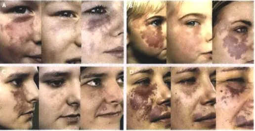
le-sion. Additionally, as shown in Figure 1-2, some patients with initial improvement
experience redarkening after a few years, whereas some patients do not respond to
the therapy at all [7, 9]. Interesting to note is that it is not possible to predict the
efficacy of the therapy before the treatment, and mechanisms underlying these poorly
responding cases are unknown.
Figure 1-2: Redarkening of PWS after PDL treatment. Each panel shows a
pa-tient before treatment (left), after six treatments of PDL (middle), and at follow up
examination after 9 years (Panel A) of 10 years (Panel B,C, and D). [7]
To improve the current therapy, we must first advance our understanding of
un-derlying vascular biology of PWS treatment. Our OFDI system is expected to play
a vital role in such clinical studies. Until now, there have been limited techniques
to assess the vasculature before and after the treatment. Histological examinations
do not provide a non-invasive visualization of the vessels. Confocal microscopy pro-vides in vivo imaging with fluorescent dyes but offers limited fields and penetration.
A clinically deployable imaging system with capillary level high-resolution and
suffi-cient penetration through the dermis would enable a better understanding of PWS physiology and improve the treatment.
1.3
Thesis Organization
Chapter 1 introduces the clinical motivation of this thesis regarding its application to study of port wine stain response to pulsed-dye laser therapy. The background study of optical coherence tomography (OCT) and optical frequency domain imag-ing (OFDI), the second-generation technology of the OCT, is covered in Chapter 2. The basic principles and theoretical performance limits of both techniques are ex-plained. The detailed design and construction of the system is presented in Chapters
3 in the following order: the optical hardware; the electronics and control device;
and the microscope interface. Chapter 4 evaluates system performance, presents a promising image of human dermal vasculature from the system, and concludes with the discussion of future work.
Chapter 2
Background
2.1
Optical Coherence Tomography
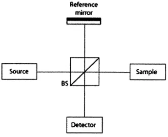
Optical coherence tomography (OCT) is an imaging modality derived from low co-herence interferometry that can provide non-invasive high-resolution imaging of the subsurface structure of scattering materials. Figure 2-1 displays a schematic of a standard OCT system. A beamsplitter divides the incident light and directs it to the reference mirror and the sample. The reflected light from the reference mirror and the backscattered light from the sample recombine and interfere at the beamsplitter output.
Reference
mirror
Figure 2-1: Schematic of OCT system. BS : Beamsplitter 19
Consider a simple case with a single mirror in the sample arm. If the source is monochromatic (coherent), the intensity of the recombined field output is proportional to the cosine of the optical path difference (OPD) Al between the reference and the sample arms, as given by Equation 2.1.
I,
JA,
12 +A,
12+ 2A,A, cos [kAl(t)],
(2.1)
where k = 27r/A is the wavenumber; A, and A., are field amplitudes incident on the reference mirror and the sample mirror, respectively. However, if the source contains a spectrum of wavelengths or frequencies, the interference is observed only for the OPD values within the coherence length. The coherence length is inversely proportional to the source spectrum. OCT uses a broadband source (low coherence), because a short coherence length leads to the 'depth selection' ability. The peak value of the output envelope is proportional to the reflectivity of the sample at the certain depth of path-match. Hence, the reflectivity profile is obtained by scanning the reference mirror.
2.1.1
Performance Limits of OCT
As described in [2], the depth resolution of OCT imaging is directly related to the coherence length of the source and is inversely proportional to the source bandwidth. For a source with a Gaussian spectrum, the axial resolution 6z is given by
oz
=2In2
( (2.2)7r nAA'
where n is the refractive index of the sample, AA is the full width at half maximum (FWHM) of the source power spectrum, and Ac is the center wavelength of the spec-trum. The transverse resolution of OCT imaging is defined as the minimum spot size of the sample beam, which is determined by the focusing property of the beam. The
transverse resolution 6x is given by
X = -A -) (2.3)
7r d
where d is the beam diameter on the lens, and
f is the focal length. A high numerical
aperture (NA) results in a smaller spot size for the same beam, which leads to high transverse resolution. However, this high transverse resolution is achieved at the expense of reduced depth of focus , which is given by5x2
b = r -.
(2.4)The depth of focus is interpreted as the depth in the sample that can be imaged, and is also referred to as the depth range. In OCT, the coherence gate decouples the axial resolution from the beam profile. Therefore, OCT imaging typically employs a low NA objective compared to confocal imaging, in order to achieve a large ranging depth.
2.1.2
Scanning Procedures and Image Display
To obtain three-dimensional information with OCT, it is necessary to implement the scanning mechanism in three directions. Depth scan, which is also called A-scan,
in z direction is accomplished by scanning the reference mirror. Transverse scan,
or B-scan, can be implemented either by a scanning mirror in the sample arm or translating the sample.
Different planes can be imaged with different scanning priorities of directions. The most common scanning method of OCT is the depth priority scan, which yields a tomographic imaging plane by measuring depth profiles at different lateral posi-tions along a line. En face imaging is also possible by performing a two-dimensional transverse scan while holding the reference mirror fixed.
2.2
Optical Frequency Domain Imaging
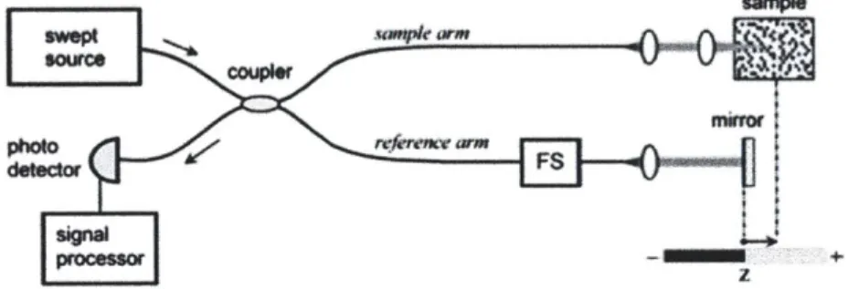
Optical Frequency Domain Imaging (OFDI) is one of the two frequency domain alter-natives for conventional (time domain) OCT. OFDI, like the other frequency domain alternatives, e.g. spectral domain OCT, enables much faster imaging with greater sensitivity by eliminating the need for scanning the reference mirror.
As discussed in [20], the principle of OFDI is based on optical frequency domain re-flectometry (OFDR). Figure 2-2 shows the basic configuration of a fiber-based OFDR system. The source output splits into the reference and the sample arms. The in-terference is detected while the wavelength of a narrowband laser is swept while the reference mirror is fixed.
Mirror
Tunable reference arm
sourc (5050)
Photodetector
Sample
Figure 2-2: Basic configuration of OFDR system
The detector current is given by
idet(t) = (Pr + P, r2 (z)dz + 2 PPfr(z)(z) cos (2k(t)z +
4(z))dz),
(2.5)where r is the detector sensitivity, q the quantum of electric charge (1.6 x 10⁻¹⁹ coulomb), hv the single photon energy, P, the optical power reflected from the refer-ence arm, P the optical power illuminating the sample. The third term represents the interferometric signal, whereas the first and second terms contribute to the back-ground. The coordinate z is defined along the depth into the sample where z = 0
is the path-match between the reference and the sample arm. r(z) and O(z) are the amplitude and the phase of the sample reflectivity at a depth z. F(z) is the coherence function of the instantaneous laser output, and k(t) = ki+ at is the wavenumber that
is varied monotonically over time t with a slope a.
If we consider, for simplicity, the case with a single reflector in the sample arm at z = zo where the input is considered coherent within the range that 1(z) = 1, the
signal current can be simplified:
i = 2 hi'(t) hv PPr(zo) cos (2(ki + at)zo). (2.6)
It is clear that the signal is proportional to the reflectivity r(zo), with the signal frequency in time (Q = 2azo) encoding the depth zo. Thus the depth reflectivity profile can be obtained by Fourier transforming the fringe signal, without having to scan the reference mirror.
2.2.1
Performance Limits of OFDI
The performance of OFDI is analyzed in the same way that conventional time domain
OCT is analyzed. For a tuning source with a Gaussian-shaped spectrum, the axial
resolution is given by [11]
21n2
(A~
6z = 21n, (2.7)
7r nAA
which is the same as Equation 2.2. Likewise, the transverse resolution is governed by the beam profile, and given by the equation 2.3.
The depth range Az is related to the sampling frequency of the digital acquisition
(DAQ) board. According to the sampling theorem, the sampling frequency must be
twice the maximum frequency of the signal from the maximum depth that can be imaged (Az) in this case. The depth range is given by [6, 20]
AZ =- (2.8)
where JA = AA/N, is the sampling wavelength interval, and N, is the number of
samples within the FWHM of the spectrum AA. This sampling interval JA should be smaller than the instantaneous linewidth of the source in order to take advantage of the coherence of the narrowband. It is also shown in [20] that the signal-to-noise
ratio (SNR) of the OFDI system is improved to
N
8(SNR)OFDI = E-(SNR)T D-OCT (2.9)
2
compared to the SNR of time domain OCT (TD-OCT).
2.2.2
Wavelength Swept Laser
As mentioned above, OFDI is operated by a tunable laser source with narrow linewidth. The laser characteristics that are most significant for OFDI can be summarized as the wavelength sweep range, the sweep repetition rate, and the instantaneous linewidth. The wavelength sweep range (AA) is related to the axial resolution (Az), as can be seen in Equation 2.7. For imaging of a biological sample with a center wavelength at 1.3 pm, the scanning range has to be wider than 100nm in order to achieve the order of 10 Im resolution. The sweep repetition rate determines the imaging speed, since one sweep delivers one A-line profile. The instantaneous linewidth is relevant to the ranging depth in a way that the narrower the linewidth, the longer the coherence length that the signal from deeper point can be detected. An instantaneous linewidth of 0.1-0.2 nm is sufficient for many biomedical applications. [3]
Figure 2-3: Schematic of polygon mirror based wavelength-scanning laser. [18]
One of the common implementations of this tunable laser source for OFDI sys-tems is a semiconductor laser with a polygon mirror scanner and a diffraction grating
based wavelength-scanning filter [18]. Figure 2-3 presents the schematic of the filter. The reflection-type filter consists of three parts: a grating that splits the incident broadband light into narrowband wavelength components; an afocal telescope with two lenses that redirects the diverging beam from the grating to the polygonal mir-ror while controlling the beam diameter; and a polygonal scanner that reflects the narrowband component that is incident perpendicular to its facet.
Oroulput
Figure 2-4: Schematic of the wavelength-scanning laser [18].
As illustrated in Figure 2-4, only the reflected wavelength component returns into a fiber-ring laser cavity, where it is amplified by a semiconductor optical amplifier
(SOA). Rotation of the polygonal mirror sweeps the wavelength of the amplified
output.
The equations of the parameters of this wavelength swept laser are summarized in Table 2.1. Note that a 100% duty cycle is achieved when all beams fall within a facet without clipping. The sweep range is determined by the free spectral range (FSR) of the laser. It has been demonstrated that the FSR can be twice as large when the wavelength-scanning filter is configured with an end reflector [13], as shown in Figure
2-5. This effect can be translated to a faster A-line rate by increasing the number of
facets to 2N and keeping the same FSR.
Table 2.1: Important parameters of the wavelength swept laser p: grating pitch Diffraction wavelength A = p(sin a + sin
#)
a: incident angle#:
diffracted angle,60: angle between the Center wavelength Ao = p(sin a
+
sinplo)
optical axis and thegrating normal
Free spectral range AA = p cos
(0)
F2 F1, F2 : Focal lengthsof the lenses
Instantaneous linewidth 6A =V4 i2AOp cos a/(Wwr) W : 1/e2 beam width
Facet-to-facet polar angle 0 = 27r/N ~ L/R N : number of facets R : polygon diameter
Polygon facet width L = 2Rtan(0/2)
Beam width at polygon facet W' = WF 2cos
#/F
1 cos aF'_ __ Ft r
AV
Figure 2-5: The configuration of the wavelength-scanning filter with an end reflector
[131.
2.2.3
Optical Frequency Shifter
In OFDI, the ranging depth is limited by the coherence length of the instantaneous output of the wavelength swept laser. The fringe visibility decreases due to the finite extent of the coherence length, as seen by the term
r(r)
in Equation 2.5. Moreover, the ranging depth is restrained by the inability to distinguish the positive and the negative frequency in an argument of a cosine function in Equations 2.5 and 2.6.One approach to achieve the maximum raging depth within the coherence length is to use an optical frequency shifter in the interferometer to shift the frequency of the detector signal [19]. Figure 2-6 illustrates a schematic of an OFDI system with an optical frequency shifter.
W$W Suampla
Figure 2-6: A basic configuration of an OFDI system with a frequency shifter
FS : frequency shifter
[191.
The signal current can be expressed as
isig(t) = l2FP. r(z)T(|z|) cos (2k(t)z + #(z) + 27rAft)dz), (2.10)
where Af is the round-trip frequency shift. Note it is the third term in Equation 2.5 with the frequency shift term
Af.
With a linear sweep in wavenumber, k(t) = ki+at;
then the detector signal frequency is given by
fig =
z + Af.
(2.11)
7r
Therefore, as shown in Figure 2-7, now the negative frequency can be mapped in the positive frequency domain, shifted by Af and both sides of the coherence range
can be used.
DEPTH. 00 -- 0 ..-. SIGNAL FREQUENCY (a) DEPTH, C 0 20 0 , SIGNAL FREQUENCY (b)Figure 2-7: Illustration of the ranging depth (a) without and (b) with a frequency
shifter [19].
2.2.4
Balanced Detection
As seen in Equation 2.1, the OCT signal comprises the background DC terms and the AC term that provides the sample information. Balanced receiver detects the oscillating term of the interferometric output by subtracting the quadrature signals of the beamsplitter. The quadratures can be detected because the transmitted field and the reflected field from the beamsplitter have a ir/2 phase difference. Figure 2-8 illustrates a conceptual schematic of a balanced receiver.
Mirror2
Detector B
input
Mirror1
Detector A
Figure 2-8: Schematic of a balanced receiver concept. The intensities at Detectors A and B are given by the following:
IA = |EA
12
=jiE1
+iE2|
2= E12+
E22+
2 cos (2kAl),(2.12)
28 FRINGE
IB = |EB12 =
jE
1 + i2E2|2 =
E±2
+ E22-2
cos (2kAl), (2.13)where E and EB are the fields at each detector; E1 and E2 are the fields incident to mirrors 1 and 2 divided from the beamsplitter, represented by the orange and green colors, respectively; k is the wave number; and Al is the OPD. The balanced detection is implemented by subtracting Equation 2.13 from Equation 2.12.
Chapter 3
System Design and Construction
This chapter describes the design and the construction of an OFDI system for dermal vasculature imaging that can be used in a clinical environment. The system consists of optical hardware, electronics, and a microscope. The whole systems is encased in a portable cart (61 cmx101.4 cmx92.9 cm, WxDxH) with a monitor and the microscope attached to it.
3.1
Optical Subsystem
There were three constraints in designing the optical hardware. First, to obtain images of capillary flow, it is necessary to achieve the performance of 5 pm resolution over a ranging depth of 3 mm. The source center wavelength was chosen to be 1300 nm, because it has low absorption in biological samples while penetrating to sufficient depth. To satisfy the specification with the chosen center wavelength, the source must be configured to achieve an FSR greater than 100 nm and a coherence length greater than 2 mm on both sides of the signal spectrum.The second constraint is the short imaging time imposed by the clinical environment. In this thesis, the imaging speed was aimed at 100 frames per second, which is equivalent to an A-line rate of 80 kHz. Last, all opto-mechanical components had to be confined to an optical breadboard of size 42 cmx 66 cm. The breadboard was mounted on a sliding shelf in the cart. Optical fibers were laid out on a panel, which was fixed under the sliding shelf.
3.1.1
Optical Source: Short Cavity Wavelength Swept Laser
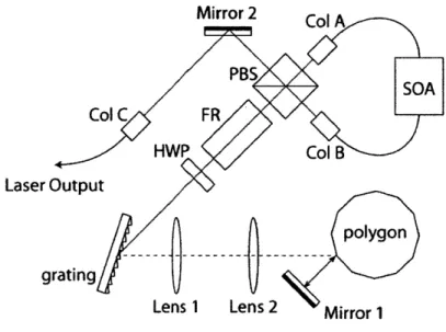
Conventional OFDI systems employ a fiber-ring cavity wavelength swept laser, which is illustrated in Section 2.2.2, Figure 2-4, where a narrow linewidth spectral filter is inside a fiber-ring cavity with a broadband gain medium. In order for one narrowband pulse to build up sufficient gain while maintaining the instantaneous linewidth and the sweep rate, the cavity length is must be as short as possible. For the desired sweep rate of 80 kHz, the total cavity length must be shorter than 2 m. However, due to the fiber length required by polarization controllers in the cavity, it was difficult to reduce the fiber length below the required level. The alternative approach was to replace the fiber coupler with a free-space beamsplitter. A schematic of this new set up is illustrated in Figure 3-1. Mirror 2 Col Ak PBS SOA Col C FR HWP Col B Laser Outputpolygon
gratingLens 1 Lens 2 Mirror 1
Figure 3-1: Schematic of the short cavity wavelength-scanning laser.
SOA : Semiconductor Optical Amplifier; PBS : Polarization beamsplitter; FR:
Fara-day rotator; HWP : Half wave plate; Col : Collimator
To ensure stability in the lasing direction, we used a polarization beamsplitter (PBS) with a Faraday rotator(FR) and a half-wave plate (HWP). Collimator A is configured so that the incident field is split into a 50/50 ratio at the PBS, while the first order diffraction is maximum at the grating so that power loss through grating is
minimum. The FR shifts the polarization by 450 in both directions of travel, whereas the HWP shifts 900 in one direction and reverses the shift to -90* in the opposition direction. Therefore, the polarization of the filter input field is perpendicular to the filter output; the output is directed to Collimator B. Collimator B is configured to have the maximum power from the transmission of the PBS, which is equivalent to the maximum coupling of the reflected output to the cavity.
As a result, the total cavity length including the double path within the filter is reduced from 3.4 m (fiber-ring) to 1.2 m. The alignment process is summarized in Appendix A
3.1.2 Interferometer
The system is based on a fiber-optic interferometer, which is more robust in terms of physical alignment. The schematic of the interferometer is provided in Figure 3-2.
To achieve a full ranging depth, an acoustooptical frequency shifter is inserted in the reference arm. The amount of optical frequency shift Af was calculated from
Af = L , (3.1)
4
where fsamp is the sampling frequency of the data acquisition (DAQ) instrument. Note we implemented a mirror to calibrate the signal in the post-processing pro-cess. This calibration compensates for the nonlinearity of the sampling as well as dispersion. A computer-controlled shutter is implemented to block the light from the calibration mirror during the imaging process. The calibration mirror and the refer-ence mirror are fixed on a motorized delay stage. The alignment process is explained in Appendix B.
reference mirror calibration mirror
crystal
Figure 3-2: Schematic of the optical subsystem.
FBG: Fiber Bragg grating; LM : Laser monitor; FS : Frequency shifter; pol :
450
polarizer
3.1.3
Polarization Sensitive Balanced Receiver
The system employs a polarization sensitive balanced detection, as illustrated in Figure 3-2. The reference arm polarization is controlled to be 45 degrees at the beamsplitter. To compensate for the dispersion caused by the crystal in the optical frequency shifter in the reference arm, the same type of crystal is inserted in the sample arm. A computer-controlled shutter is installed in the sample arm to block the backscattered sample field while only the reference field is recorded to obtain a background signal that is used in the post processing process.
3.1.4
Breadboard Assembly
The breadboard construction of the whole optical subsystem is photographed in Fig-ure 3-3 and FigFig-ure 3-5.
Figure 3-3: Photograph of the optical breadboard on a sliding shelf.
To construct the system in a compact space, aluminum mounts were designed for the beamsplitters, the polygonal mirror, and the SOA. The designed mounts are presented in Figure 3-4. The design considerations include compatibility with
commercial opto-mechanical products; placement of the optical post and the clamping forks of surrounding elements; and flexibility in position adjustment. The drawings for each component are provided in Appendix C.
(A)
I
a
(B)Figure 3-4: The designed mounts for (A) the beamsplitters in receiver, (B) the polyg-onal scanner and (C) the SOA.
3.2
Control Box
The metal case that contains all electronics will be referred to as the control box
from this point. The control box is mounted on a sliding guiderail and placed in the
portable cart.
3.2.1
Case Design
The case was designed with Protocase Designer 4 software. Figure 3-6 presents the
design of the case. The width and the depth were constrained to fit in a standard
server rack in the cart, and the height was 4 U (rack server units).
Figure 3-6: Schematic of the empty Control Box.
As seen in Figure 3-7, the front panel of the case includes ventilation holes, power
switches, and BNC outputs for monitoring the laser and the galvanometer scanner.
The back panel serves as a connection interface where all wires are mounted with a
mate-and-lock cable connectors. The construction involved re-assembling of all cables
with appropriate connectors. For cables with high currents, we installed mechanical
screw fixers to fix the cables with cable ties on the screws.
(A)
Figure 3-7: The Control Box interface viewed from (A) the front and (B) the back.
3.2.2
Power Connection
The control box encloses all the power supplies of the system components. Each
component was matched with an appropriate power supply. The scheme of the power
control is illustrated in Figure 3-8. The main switch connects 115 V AC input to
the main LED and other first level electronics such as ventilation fans; a
temper-ature monitor; the delay stage with the reference and the calibration mirrors; the
balanced detectors in the polarization sensitive receiver part; and the motorized
lin-ear stages in the microscope. The power adapters that connect components to AC
power are not depicted in the diagram. Secondary switches connect the 115V DV
input to the optical frequency shifter, the power supplies of the galvanometer scanner
driver, the polygon driver, and the laser driver. Enable switches are installed for the galvanometer scanner, the polygon scanner, and the SOA.
115V input ,... _Freguency ... . shifter
|main LED2Iaeter
Fans X3
24V
PS
*
i48V
PS
- Polyon scannerTemperatu~re |-eav stage VP --
O
monitor rDey e
PhotodetetrX Microscope
stagze X2
Figure 3-8: Control Box power connection. PS : power supply
3.2.3
Component Layout
One of the challenges in the construction was placing all components in the compact space. To make the best use of the space, some components were stacked on a plate supported by aluminium posts. The bottom of the control box was designed so that the components can be fixed with standard screws or cable ties. Figure 3-9 presents a photograph of the completed control box taken from the top without the top panel.
3.3
Microscope
The microscope provides the interface between the sample and the optical subsystem. The microscope subsystem comprises an objective lens, a two dimensional linear stage, and a galvanometer mirror scanner. The microscope is attached to the cart via an articulating arm so that it can be placed as desired while imaging patients.
3.3.1
Lens selection
IAs mentioned in Section 2.1.1, a good transverse resolution is achieved via a high
NA at the expense of large depth of focus. In the ideal case, it is desired to maintain
high transverse resolution over the full depth of focus (Figure 3-10). One of the
low NA
ideal case
high NA
Imaging
Depth
Figure 3-10: The transverse resolution and the depth of focus - coupled with the NA
ideas to address this problem is to image three different depth sections with three separate light sources that are centered at different wavelengths. By taking advantage of chromatic aberration, different sources can be focused at different depth planes,
which is illustrated in Figure 3-11.
To select the objective lens that provides sufficient chromatic aberration to focus different source at enough separation distance, beam diameters over the depth have been calculated with ZEMAX software. LSM02 from Thorlabs was chosen, since the total focal shift was 1 mm in free space, which translates to sufficient depth of focus when imaging biological samples. Figure 3-12 plots the root mean square (RMS) beam
(A)
(B)
* p I p t I I I I I * I I * I I I I p~I
I I I I S I I I S I I I I IImaging
Depth
Figure 3-11: Improvement in transverse resolution with tri-band source
spot radius along the depth. The focal shift
Af
was calculated from the equation:
Af
=
zO
-
z, where z
0is the back focal length from the lens surface at the wavelength
1300 nm.
160 140 120 100 80 60 40 20 0 -- 1000nm * 1300nm ,--1700nm -1.5-1.3-1.1-0.9-0.7-0.5-0.3-0.10.1 0.3 0.5 0.7 0.9 1.1 1.3 1.5 A focus (mm)Figure 3-12: RMS Spot radius.
3.3.2
Transverse Scanning
We have implemented an one-dimensional galvanometer scanner to achieve a
tomo-graphic cross-sectional image, and a bi-directional motorized linear stage to move the
lens with respect to the sample to obtain volume information as well as to adjust the
lens position. The scan priority is diagrammed in Figure 3-13
Figure 3-13: Schematic of the scanning mechanism. red : z-direction depth scan
provided by the laser sweep; blue : x-direction transverse scan provided by the
gal-vanometer; green : y-direction transverse scan provided by the linear stage.
3.3.3
Objective Interface Design
The objective interface is designed to image the dermal microvasculature of human
patients. To facilitate the process, a commercial adhesive window for dermal confocal
imaging is employed. The window is designed to interface a magnetic ring and the
imaging site. The magnetic ring attaches to an adapter piece, which can be adjusted
to find the best focus. The magnet mechanism enables simple attachment and
de-tachment with an outer ring. The basic concept is diagramed in Figure 3-14, and a
photograph of the microscope is shown in Figure 3-15.
(A) Window adaptor Lens I
I
I
(B) MagnetOtr Outer ring Magnetic ring Adhesive window IFigure 3-14: Schematic of the skin-objective interface (A) without the outer ring and (B) with the outer ring.
Lens (inside)
Figure 3-15: A photograph or the microscope. 45
3.4
Construction
The whole system is encased in a portable cart (61 cm x 101.4 cmx92.9 cm, W x D x H) with a monitor and the microscope attached to it. A computer (Windows 7, a 2.67 MHz quad core CPU, a 12 GB RAM) of a height of 1 U (rack server unit) is inserted at the top. The optical breadboard where all optical elements are fixed with clamping forks is mounted on a sliding server rack self. A thin aluminum panel was attached under the sliding shelf. On the panel, fiber based elements such as couplers and circulators were laid out. The control box is mounted on a set of guide rail and installed under the optical breadboard. At the bottom of the cart, an electrical power isolator is installed.
The microscope is mounted on an articulating arm (42 inches maximum length). The double arm is gas spring assisted so it can be effortlessly pulled and positioned as desired. It provides up to 42" of vertical and horizontal adjustment with 180 degrees rotation. The head part is ball-jointed to allow the fine-tuning of the position. The arm is fixed on the left panel of the cart. Cables that connects controllers in the controller box to the galvanometer and the linear stage are fixed tight with tie straps so the connections are robust. The Optical fiber in the sample arm is protected in a
3 mm diameter outer jacket and also tied securely to the microscope with tie straps.
Figure 3-16 shows a schematic of the complete system on the cart. A complete list of parts is included in Appendix C and a list of connectors and electronic cable components is included in Appendix D.
3.4.1
Challenges
The main challenge of this work was building the system from scratch. Component purchases involved comparing similar products from different manufacturers and se-lecting the ones that meet desired specifications. Simulation and design required softwares (Zemax and Solidworks) that I have never been exposed to before. Basic resources such as screws and bolts also had to be purchased as well as electrical cable connectors and wire crimps.
(A) (B)
Figure 3-16: System. (A) A Schematic and (B) a photograph.
Like other experimental studies, this project required solid understanding of the
theory as well as experience and insight in laboratory. As I did not have a background
in Optics, understanding the physics of OCT and OFDI was challenging in the
begin-ning. In the laboratory, aligning all free-space optical components to minimize power
loss have been quite tedious.
Planning had gone through a great amount of trial-and-error, specifically for the
planning the work in between the purchase and the delivery of a component. Devices
occasionally broke down, identifying the cause and repairing them also took some
unexpected time.
Chapter 4
Performance and Future Work
This chapter presents the performance of the system. The image obtained from the system is what we believe to be the first image of human dermal vasculature imaged without any exogenous agents. The system will be further improved and applied for clinical studies in dermatology in the future.
4.1
Laser Performance
The performance of the system is largely determined by the source characteris-tics, since the balanced receiver and DAQ are commercial products and the image-processing algorithm is already optimized for vasculature OFDI.
4.1.1
Coherence Length
The coherence length was measured by finding the calibration mirror delay that causes the fringe amplitude to decrease to the half of the path-match fringe amplitude. The path-match was found with an RF spectrum analyzer when the peak occurred at a 40 MHz signal frequency. The coherence length was measured to be 3.15 mm to the positive side of the spectrum and 3.30 mm to the negative side of the spectrum, which satisfies the goal described in Chapter 3.1. Figure 4-1 shows the oscilloscope signals at the pathmatch and at the maximum ranging depths.
(A) Waveform
at OPD = 3.15 mm
(B) Waveform
at the path-match
(C) Waveform
at OPD = -3.30 mm
Figure 4-1: The oscilloscope signals.
4.1.2
Source Spectrum
As described in Section 2.2.1, the source spectrum determines the axial resolution of OFDI. The source had a bandwidth of 140 nm, as measured by an optical spectrum analyzer (OSA).
4.2
Image and Discussion
The vasculature of human cheek skin is imaged for testing purposes. The adhesive window with index-matching gel was placed on the cheek of a subject while the person was sitting on a chair. The field of view was set at 7.2 mm x 5.6 mm. Data acquisition time was 54 seconds. Figure 4-2 displays an en face image of human cheek vasculature. The vessels are color-mapped along the depth into the skin: yellow (superficial) to
red (deep).
We believe optimization of the processing algorithm and scan pattern will provide more contrast. In addition, employing thicker objective window with anti-reflective
Figure 4-2: In-vivo image of the human cheek vasculature.
coating will also remove the undesired vertical striation.
4.3
Future Work
Plans for further research can be summarized as (1) application of the system for
the study of port wine stain (PWS) treatment and (2) optimization of optical system
performance.
After the system is validated, we will investigate the kinetics of microvascular
response of PWS to the pulsed-dye laser (PDL) therapy. We will be working with
dermatologists in Massachusetts General Hospital and Brigham and Women Hospital.
We will recruit and obtain consent from a group of adult volunteers seeking treatment
for PWS. The patients will be treated up to 8 times, and image of capillary structure in
lesion will be taken prior and immediately after the treatments, and also at follow-up appointments. This study aims to provide guidelines for the most effective parameters for the therapy through understanding of the biology at microvascular level.
While the current system presents valuable and promising imaging of capillary structure, its performance can still be improved. To better discriminate capillaries in skin, a uniform transverse resolution throughout the depth is advantageous. In the current OFDI system, high transverse resolution is limited to 25-30m for a 1mm depth of field. Higher resolution is usually achieved at the expense of penetration depth. I have planned to develop a laser source that can penetrate deeper (2mm) in the skin with better resolution (-10m). The concept has been validated through simulation results. As discussed in Section 3.3.1, the lens was chosen so that it provides sufficient focal shifts between three different bands of wavelengths (1000 nm, 1300 nm, and 1700 nm).
The shorter and longer regime sources will be incorporated into the current system. Since different wavelengths focus at different depths with longer wavelength at a deeper position, three separate band of signal is obtained. These data can be merged in to one image at the processing step.
Appendix A
Short Cavity WSL Alignment
1. Collimation adjustment (with a collimator to mirror distance of 25 cm)
(a) Adjust collimator(3) first.
(b) Collmator(1) and (2) are connected to the PM fiber which has a
differ-ent NA to SMF, so they can not be collimated by monitoring the coupled power. Adjust collimation by observing the beam size so that it is main-tained constant over the distance.
2. Height Matching
(a) All heights should match the opening of the polygon mirror.
(b) Adjust collimators first, and also adjust the PBS mount so that the beam
does not bend up or down after the PBS. Also adjust the vertical angle of the grating.
3. Layout and polarization adjustment
(a) Mount the SOA so that its arrow points toward the direction of collima-tor(1).
(b) Adjust the mounting angle of collimator(1) to have 50/50 split after the
PBS.
(c) Adjust the mounting angle of collimator(2) to have maximum light going into the telescope.
4. Output coupling
(a) Maximize the coupling between the collimator(1) and (3) by adjusting the knobs on the output mirror and collimator(3).
5. Source alignment
(a) Place a temporary mirror in place of the grating, and align to gain lasing power of 50mW at least in the free space before the collimator(3). Ad-just the knobs on the temporary mirror first and then the ones on the
collimator(2).
6. Telescope alignment
(a) The half wave plate can be either at 22.5 or 67.5. Choose the angle that makes the 0th order diffraction power of the grating the minimum.
Appendix B
Frequency Shifter Alignment
1. Match heights of the collimators and the AO holes.
2. Obtain a good 0th order coupling with the AO off. With the AO off, diffraction does not occur so the beam must be in a regular circular shape. If it is chipped, this indicates that it does not go through the crystal properly.
3. Turn the AO on. Twig the rotation mount slightly to make one of the first order
beam is the brightest. Place the IR card long enough away from the beam so there is clear separation. Taking out the receiving collimator may help. Check whether it is the first order by switching the AO on and off. With the AO off, only the 0th order exists.
4. Put the receiving collimator back in, and turn the AO off. Align again for a good Oth order coupling. Do not touch the first collimator or the AO. Only adjust the second collimator. (This coupling need not be as good as the coupling at Step 2.)
5. Turn the AO on, adjust lateral angle of the second collimator to find the 1st
order spot. Try to remember where the bright 1st order was and turn to that direction. This turn may be quite far. Note that 1st order power can be very small.
6. Slowly optimize this 1st order coupling, by adjusting the collimators, then
ad-justing the AO. Care must be taken not to lose the 1st order coupling.
Appendix C
Components List
Part Components Vendor Model Number
Housing rack-case
Housing custom control box
Housing sliding guide rail
supernicro protocase
McMaster-Carr 2005A7
Housing sliding shelf Digi-Key
Housing Housig Housing sponge arm cardboard
Bread Board breadboard
McMaster-Carr ICW USA bellcomb Thorlabs RSVS1926BK1-ND 8458K14 MB1824
for the control box ;Narrow Lock-Open Side-Mount STL Drawer Slide FuN Extension, 24" L, 26" L TrMvel, 110 lb/Pr
SHELF SUDE 26.1X16.6X1.5 BLACK Hammond Manufacturing
(#:RSVS1926BK1)
Improved-Strength Basic Alurinum Honeycomb Panel, 1/8' Thick, 24" X 24"
Alrninunm Breadboard, 18" x 24" x 1/2', 1/4"-20 Threaded
Blue Sky Research
Wavelength Electronics Wavelength Electronics Wavelength Electronics
FMXL532-005-SAOB 532 nrn fiber coupled laser, 5 mW
LDD400 laser diode current supply
LDDEVALP WCB201 evaluation board cable
![Figure 1-1: Recent images of microvasculature obtained by (A) OMAG : images of human palm capillary networks in different depth (A-A) 400-450 pm, (A-B) 450-650 pm, (A-C) 450-650-780 tm, and (A-D) 780-1100 pm [1]; and (B)](https://thumb-eu.123doks.com/thumbv2/123doknet/14732252.573261/14.918.198.698.677.918/figure-recent-images-microvasculature-obtained-capillary-networks-different.webp)
![Figure 2-3: Schematic of polygon mirror based wavelength-scanning laser. [18]](https://thumb-eu.123doks.com/thumbv2/123doknet/14732252.573261/24.918.170.675.726.940/figure-schematic-polygon-mirror-based-wavelength-scanning-laser.webp)
![Figure 2-4: Schematic of the wavelength-scanning laser [18].](https://thumb-eu.123doks.com/thumbv2/123doknet/14732252.573261/25.918.227.677.367.647/figure-schematic-wavelength-scanning-laser.webp)

![Figure 2-7: Illustration of the ranging depth (a) without and (b) with a frequency shifter [19].](https://thumb-eu.123doks.com/thumbv2/123doknet/14732252.573261/28.918.194.674.176.353/figure-illustration-ranging-depth-b-frequency-shifter.webp)