Design, Fabrication, and Testing of a Scanning
Probe Potentiometer
by
Emily Barbara Cooper
Submitted to the Department of Electrical Engineering and Computer
Science
in partial fulfillment of the requirements for the degrees of
Bachelor of Science in Electrical Science and Engineering
and
Master of Engineering in Electrical Engineering and Computer Science
at the
MASSACHUSETTS INSTITUTE OF TECHNOLOGY
June 2000
©
Emily Barbara Cooper, MM. All rights reserved.
The author hereby grants to MIT permission to reproduce and
distribute publicly paper and electronic copies of this thesis document
in whole or in part.
Author....
Departme
Certifiedby...
MASSACHUSETTS INSTITUT OF TECHNOLOGYJUL
27 2000
LIBRARI ...of Electrical Engineering and Computer Science
May 5, 2000
-v
Scott R. Manalis
Assistant Professor
ihe
Sepervisor
Accepted by...
.
...
..
Arthur C. Smith
Chairman, Department Committee on Graduate Students
Design, Fabrication, and Testing of a Scanning Probe
Potentiometer
by
Emily Barbara Cooper
Submitted to the Department of Electrical Engineering and Computer Science on May 5, 2000, in partial fulfillment of the
requirements for the degrees of
Bachelor of Science in Electrical Science and Engineering and
Master of Engineering in Electrical Engineering and Computer Science
Abstract
The scanning probe potentiometer (SPP) represents the union of two familar tools: a scanning probe, as used in atomic force microscopy, and an ion-sensitive field effect de-vice. The addition of charge sensing capability to a traditional scanning probe, along with the use of a set of microfluidic deliver channels form the basis for a novel exper-imental platform for non-optical ensemble measurements of biological interaction. In previous experiments, we demonstrated the SPP as a scalable, high-resolution tool for directly synthesizing, switching and investigating nanoliter volumes in an array of discrete solutions.
In future work, we intend to use the SPP to probe discrete molecular interactions, such as DNA hybridization. We also envision detection involving lipid bilayers as an interfaces to the devices. The lipid membrane can serve as an immobilization matrix for proteins, or define a charge reservoir, with the goal of creating chemically specific hybrid device. A key step in these experiments is the preparation of the sensor surface of the SPP to be completely free of organic contaminants. Such contaminants can interfere with membrane, or protein adhesion. Post-processing cleaning in acids has resulted in electrical failure of previously fabricated SPP devices.
This thesis presents a redesign of the fabrication process to make SPPs that are robust to biological surface preparation techniques. A process flow, which was carried out in MIT Microsystems Technologies Laboratories, is presented. Devices were fabri-cated with no metalization on the cantilever, which allows uniform, effective electrical passivation. Electrical characterization of resulting devices is presented. Compared with previous microfabrication efforts, this process resulted in increased sensitivity, decreased hysteresis, and robustness to cleaning and surface preparation techniques. Thesis Supervisor: Scott R. Manalis
Acknowledgments
I am fortunate to have the opportunity to work with my advisor, Professor Scott
Manalis, in this very exciting time of our group's development. His technical advice and encouragement make this research go.
The work presented in this thesis is part of ongoing collaboration with many individuals and organizations.
I would like to thank the Zyomyx team: Dr. Peter Wagner, Dr. Peter Kernen,
and Dr. Frank Zaugg, who especially help us understand surfaces and membranes. Thanks also to Dr. Dean Hafeman of Molecular devices who has shared his insight into the LAPS sensor in terms of functionality and processing experience.
Dr. Steve Minne of Nanodevices was very kind to pull the lever on the DRYTEK2 at Stanford's CIS facility.
Many thanks to our capable and competent UROPs, Josh Juster and Rikky Mueller who help set up experiments.
We are grateful to Analog Devices for the donation of p-type SOI, and Professor Jesus del Alamo for organizing the donation.
The students and staff of the Microsystems Technologies Labs have been extremely generous with their time and processing knowledge, especially Dr. Vicky Diadiuk, Tom Takacs, Kurt Broderick, Bernard Alamariu, Andrew Ritenour, and Joel Vold-man.
Thank you to Roberto Aimi, who reminds me to sleep.
Funding for this research was provided by the Media Laboratory's Things That Think (TTT) consortium. I have been supported by a graduate research fellowship from Motorola.
Contents
1 Introduction
1.1 Scanning Probes . . . .
1.2 Electrolyte-Insulator-Semiconductor Devices
1.3 Thesis Goals . . . .
2 Electrical Measurement in Solution
2.1 Charge Screening in Solution . . . .
2.2 Applications and Experiments . . . .
2.2.1 Discrete Molecular Interactions . . .
2.2.2 Membrane Impedance Measurements
2.3 Surface Cleaning Techniques . . . .
3 Fabrication Considerations
3.1 Previous Device Design . . . .
3.2 New Design . . . ..
3.2.1 Passivation . . . .
3.2.2 Si02-Si3N4 interface . . . .
3.2.3 Stress Balancing in Si02 layers and Dopant Diffusion
3.2.4 Wafer through-etch Release . . . .
3.3 Fabrication Results . . . .
4 Experimental
4.1 Experimental Setup . . . .
4.2 Photocurrent Response . . . .
4.3 Current vs. Voltage Response before and after H20 2 + H2SO4 cleaning 27
5 Conclusions and Directions of Future Work 30
A TSUPREM4 Simulation Code 32
B Theoretical Derivation of Depletion region width 35
C Fabrication Details 37 6 . . . . 6 . . . . 7 . . . . . 7 9 9 . . . . 10 . . . . 11 . .. . 11 . .. . 12 13 . . . . 14 - . . . 14 . . . . 14 . . . . 15 . . . . 16 . . . . 16 . . . . 21 25 25 . . . . 2 5
List of Figures
2-1 Force vs. distance characterization of charge double layer in solution. After Hu et.
al. . . . . .. . . . . . . .- 10
3-1 Optical Micrograph of Microfluidic channels. In this image, flow is directed down-wards. Light "points" are channels walls, which taper into the junction. . . . . . 13
3-2 Optical Micrograph of Original SPP devices. Active area is square region on tip at right. Metalization junction is circular overlap of silicon and aluminum (brighter). 15 3-3 TSUPREM4 simulation of dopant diffusion and oxidation. The left figure shows implant profile before dopant diffusion. The line at 2.2 pm marks the lower bound-ary of the silicon, where it contacts the buried oxide layer of SOI. The right figure shows the implant profile after the diffusion step where the dopant is driven into the surface, and the passivation oxide is grown. The passivation oxide extends from 0-1 pm, the silicon from 1 to 2.2 pm, and the buried oxide is beyond 2.2 pm into the device. . . . .. . . .. . . . .. 17
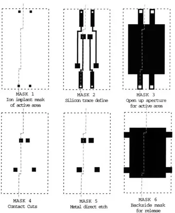
3-4 Mask Schematic, not to scale. Cut lines show where cross-sections in process flow are taken. . . . .. . . .. . . . 18
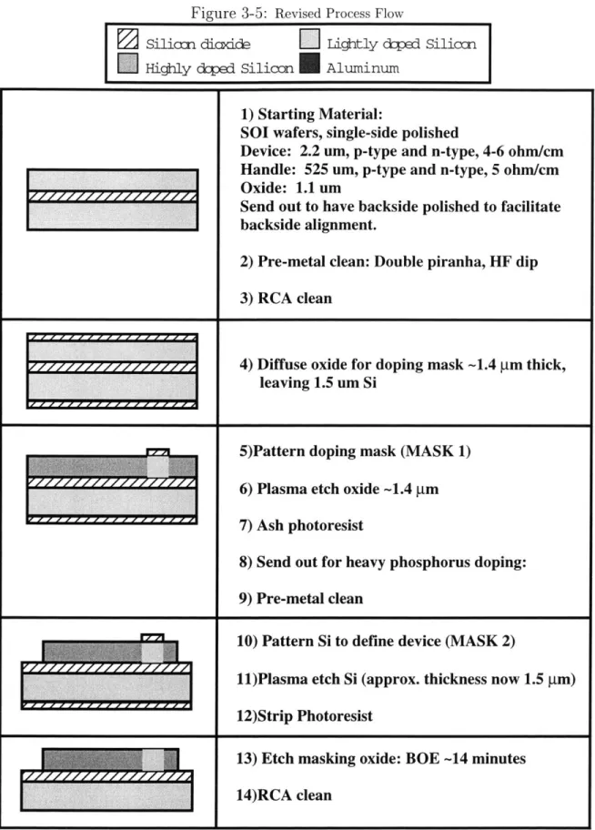
3-5 Revised Process Flow . . . . .. . . . . .. 19
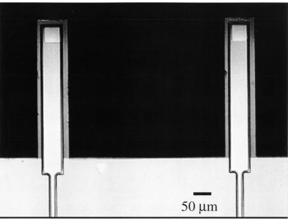
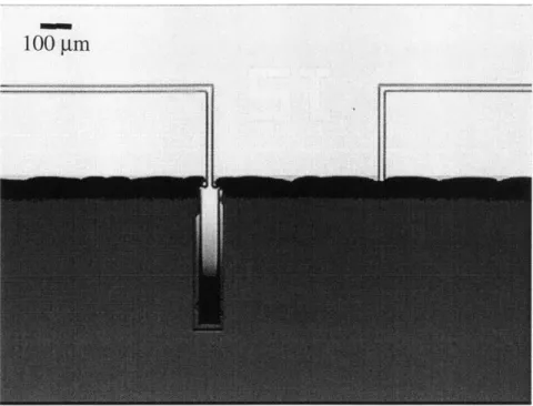
3-6 Optical micrograph of an ideally released pair of probes. The active area on these devices is 15 pm on a side. . . . . 22
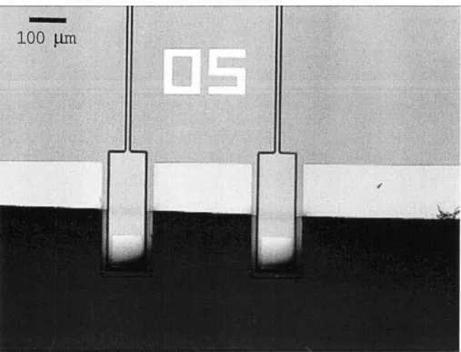
3-7 Optical micrograph of underetched structure. . . . . 23
3-8 Optical micrograph of overetched structure. Transparent film is silicon dioxide. . 23 3-9 Optical micrograph showing details of typical breakage scenario. Devices were weakened by over etch. Frictional forces due to gummy, partially dissolved pho-toresist caused breakage. . . . .. . . . 24
3-10 Close-up of same . . . . 24
4-1 Experimental Setup . . . . 26
4-2 Photocurrent vs. Time . . . . 27
Chapter 1
Introduction
In biotechnology and medical diagnostics, there is a need for detection devices capable of continuous, selective, rapid, and extremely sensitive measurements in small volumes of reagents. There is impetus for development of non-optical biological analysis meth-ods, because of the cost and difficulty introduced by tagging analytes with optically active tags and because of the time limitation imposed by the bleaching of many optical tags as they are exposed to light. Further, tagging molecules may interfere with molecular interactions of interest. Perhaps the most limiting aspect of optical methods is that it reveals no clear path to in vivo measurements for diagnostic use. Microfabrication techniques can be used to miniaturize reagent delivery systems and reaction chambers, as well as for development of novel, non-optical detection devices sensitive to very small amounts of charge. Such systems offer potential for analysis of pathogen mechanisms at the molecular level, protein binding and transport, and genetic analysis.
1.1
Scanning Probes
The scanning probe potentiometer (SPP) demonstrates the union of two non-optical detection tools: the atomic force microscope (AFM) [6], and chemically sensitive field effect devices [4, 5, 16, 20]. The AFM scans a microfabricated silicon-based cantilever across a surface while optically monitoring the deflection of the cantilever due to force interactions between the tip and surface. It allows the mapping of surface topologies at atomic resolution, far below optical limits. This extreme force sensitivity has allowed mapping of biological cells, proteins, and even DNA [20, 22, 21]. The development of chemically sensitive scanning probes promises the additional capability of detecting molecular charge.
1.2
Electrolyte-Insulator-Semiconductor Devices
The ion-sensitive field-effect transistor (ISFET) [4, 5] is a familiar structure which
can be thought of as a metal-oxide-semiconductor field-effect transistor (MOSFET) in which the gate electrode has been replaced by a fluidic contact. The surface poten-tial at the solution-gate insulator interface controls the conduction channel between source and drain of the device [4, 5, 25]. The light addressable potentiometric sensor
(LAPS) structure[16], after which the SPP device is more closely designed, is based
on the same principle of field-effect detection of surface potential at the electrolyte interface. The LAPS is analogous to a MOS capacitor with a single bulk contact, where chemical interactions on the insulator surface induce a depletion region in the underlying silicon. The size of this depletion region, and hence the surface charge on the device, is then inferred from the amplitude of a photocurrent induced by intensity-modulated laser illumination on the back face of the device. The LAPS structure has the additional advantage of having only one device contact (the other bias voltage being applied through the electrolyte). This means that only one electrical trace must be fabricated on the cantilever structure, minimizing the size of the SPP structure, which leads to greater sensing resolution and ease of manipulation.
Chemical field effect devices, such as the ISFET, and the light addressable poten-tiometric sensor (LAPS), offer three main advances over optical methods in biochemi-cal detection. First, they allow direct electribiochemi-cal detection of molecular or ionic charge, which eliminates the cost, time-consumption, and complexity of tagging reagents with chromophores, fluorophores, or optically active enzymes. Secondly, microscale fabri-cation allows consumption of smaller volumes of analyte than traditional bench-top chemistry. Direct detection of DNA hybridization has been demonstrated with a 2.4
pL sample volume by an ISFET with a sensing area of 20 pm by 500 pm [17, 24]. The LAPS device has been used to detect the metabolic response of cells to environmental
chemical change in volumes as small as a nanoliter [16]. A goal of this project is to push resolution of such devices further, allowing single-cell analysis and sensitivity to dilute analyte concentrations. Finally, the scalability of electronic sensors demon-strates promise for in vivo medical diagnostic use. Such a sensor can be non-invasive or minimally invasive. Associated signal processing hardware and software need not be integrated completely into such a sensor, but can run remotely.
1.3
Thesis Goals
In testing prototype SPP devices, sensor surface preparation techniques have proven to be the key to effectively interfacing to biology, whether discrete molecules or lipid bilayer membranes are studied. Previous microfabrication efforts, while demonstrat-ing the capability of the SPP as a detection tool, have produced devices which are
not robust to surface cleaning techniques. This is primarily due to a metal trace running the length of the scanning probe which limits subsequent passivation meth-ods. A new design has been microfabricated, electrically characterized, and tested for compatibility with surface preparation techniques.
Chapter 2 discusses the central problem of electronic biological detection-ionic screening in solution. The phenomenon of ionic screening of charged particles and the sensor surface is discussed. This implies classes of experiments and applications to which the SPP is suited. One class of such experiments is concerned with discrete molecules bound directly to the sensor surface-within the charge double layer. An-other class of experiments relies on the use of biological membranes as platforms for protein studies.
In Chapter 3, device fabrication will be discussed. The previous SPP design will be presented and analyzed to motivate the design changes outlined. Key fabrication steps will be discussed and potential methods compared. A process flow for the new SPP devices will be presented.
Chapter 4 will discuss experimental setup and results. The physical setup and electrical detection circuit will be discussed. Electrical characteristics of the micro-fabricated devices will be presented and compared with previous SPP efforts, as well as LAPS devices.
In concluding, Chapter 5 will discuss the direction of future development of the SPP based on the insight from the work presented here.
Chapter 2
Electrical Measurement in Solution
2.1
Charge Screening in Solution
The SPP is intended for direct electrical measurements of interactions of ensembles of biomolecules. Electrical measurements in solution are complicated by the phe-nomenon of ionic screening. Charged surfaces and macromolecules attract highly mobile counter-ions, which effectively shield their charge.
In 1853, Helmholtz proposed that this charge double layer could be modeled as a parallel plate capacitor whose plates were equally and oppositely charged and spaced at the double layer thickness. This model was most substantively modified by Gouy and Chapman, who described the spatial arrangement of the double layer as a de-caying exponential. Further modifications of this model include a compact layer of absorbed surface ions that, because of their finite diameter, inhabit a "plane of closest approach" [15].
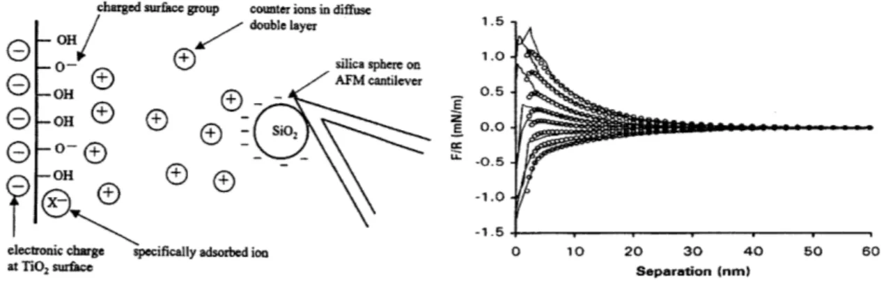
There is an electrical double layer in the electrolyte phase associated with each surface of interest in our system-the sensor surface, and a charged macromolecule. A particularly relevant visualization of charge interaction in such a system was demon-strated by Hu, et. al [18]. Their experimental arrangement is described in Figure 2.1. A negatively charge silica bead is attached to an AFM cantilever and brought within close proximity of titanium oxide surface. Force interactions between the bead and insulator surface are measured by deflection of the AFM cantilever. In the bulk solution, far from the surface, there is no force interaction. Charge interaction occurs only within 10-20 nm of the insulator surface, within the Debye length of this system, a .001 M KCL solution at pH 5.5. The force vs. distance curves shown in Figure 2.1
are measured by varying the bias voltage applied to the TiO2 surface, from top to
bottom: -.9, -.8, -.7, -.5, -.43, -.2, 0, +.5 V.
the electric field and potential decay to 1/e of their value at the interface (either the sensor surface, or the surface of the charged macromolecule):
1 6 RT
K 2z2F2c'
where c is the permittivity of the solution, R is the gas constant, T is temperature,
F is Faraday's constant, c is the solute concentration, and z is ionic charge. We can
see from this expression that the Debye length is inversely proportional to the square root of solute concentration. For physiological conditions of a 0.1 M salt solution, the Debye length is about 1 nm.
charged surface group counter ions in diffuse - OH/ double layer
- 0 -silica s
GOH®
AFM co
OH 2e- 0-- SD
-OH
electronic charge specifically adsorbed ion at TiO2surface phere on antilever E E 1.5 . 1.0. 0.5. 0.0. -0.5--1.0. -1.5 0 10 20 30 40 Separation (nm)
Figure 2-1: Force vs. distance characterization of charge double layer in solution. After Hu et. al.
2.2
Applications and Experiments
The Debye length prescribes a region of charge sensitivity in the vicinity of the sensor surface. In light of this, there are two general forms of experiments that the SPP is designed to address. The first is concerned with detecting charge associated with an immobilized macromolecule of interest, and detecting changes in charge config-uration as these molecules interact with other molecules or environmental factors. The second class of experiments relies on the use of a lipid bilayer membrane as an interface. Membranes serve as natural sites for immobilization of proteins and allow the definition of an electrolyte reservoir between the membrane and device, whose electrical properties can be carefully controlled.
2.2.1
Discrete Molecular Interactions
An example of the first type of experiment is detection of DNA hybridization on the SPP. On the backbone of a single strand of DNA is a single negative charge associated with each base. We consider an experiment where single-stranded DNA is attached to the sensor surface. Upon hybridization, the surface charge on the sensor is expected to double. Indeed, this experiment was conducted by Souteyrand et. al. [25] on a ChemFET device with circular sensor region about 3000 prm in diameter and in a .01 M buffer solution. Clear shifts in the flat-band potential of the semiconductor were observed during hybridization. The spacing between paces on a DNA strand is about 34 Angstroms, so we may consider a sequence of about 10 bases to be withing the Debye length under these conditions.
The SPP offers here the possibility of detection with far smaller sample size. Further, the device could be extended to make a measurement similar to the Hu et. al. [18] measurement described above. An array of DNA sequences on a DNA chip' could be scanned with the SPP making not only force-distance measurements, but charge-distance measurements, where binding affinity is correlated to the slope of the charge-distance measurements. This is a direct corollary to the variation of slopes measured at different surface potentials in the Hu, et. al. experiment.
2.2.2
Membrane Impedance Measurements
The second class of experiments is concerned with the use of membranes as a natural interface between the sensor and analyte. Supported lipid bilayers, separated from the sensor surface by a thin (~nanometer-thick) layer of water or polymer maintains the thermodynamic and structural properties of free bilayers [23]. Each interface (device to electrolyte reservoir, membrane to outer electrolyte) in the resulting hybrid system can be modeled as a parallel RC pair. By impedance analysis over over a frequency
range of 10-105 Hz, changes in the capacitance of the electrodes, the capacitance
of the membrane, and the resistance of the membrane can be discriminated [14]. Integration of ion-specific pores in the membrane forms a chemically specific detector, whose membrane resistance changes only in response to the ion of interest. The authors [23] cite for the potential to increase sensitivity of such measurements through use of field-effect sensors.
Tethered membranes on electrodes have further been used to demonstrate high-gain ion-channel switches by similar conductance measurements [12]. Finally mem-branes can define a charge reservoir, either by enclosure with a biological membrane,
'A DNA chip is a combinatorial array of DNA sequences which have been patterned base by
base with photolithographic methods. The current generation of DNA chips, which use optical fluorescence for detection of hybridization, are limited by square field sizes of tens of microns on a side.
or definition by a semi-permeable gel matrix, such that electrical effects are dominated
by a specific ion of interest.
2.3
Surface Cleaning Techniques
Surface preparation of the potentiometer is critical for any biological experiment. In the first set of experiments, surface preparation is, of course, analyte dependent. However, a thorough clean of organic contaminants is necessary in any case. This accomplishes two goals. First, any (possibly charged) contaminants that may effect the electrical properties of the device are removed so that the device has optimal electrical response. Secondly, it provides a clean surface for adsorption of analyte.
The sensitivity of measurements in experiments involving lipid bilayers is crit-ically dependent on the uniformity of the surface membrane. For the capacitance measurements, 97% of the surface area of the sensor must be covered such that the measurement is not dominated by capacitance from defects in membrane coverage. Stelzle [26] has shown that tightly packed bilayers with 99.5% coverage are achievable with proper surface preparation techniques. Surface treatment invariably begins with a dilute acid etch to remove all residual organic and inorganic surface contaminants.
Chapter 3
Fabrication Considerations
We have attempted to coat the SPP sensor surface with lipid bilayers by the vesicle
spreading method [13]. This is facilitated by an array of open microfluidic channels
developed for use with the SPP to allow rapid analyte evaluation and delivery of molecules for sensor surface modification.
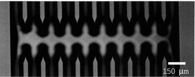
An optical micrograph of these channels is shown in Figure 3.1. The channels form a fluidic delivery system which is open to the air on the top surface, allowing access by the scanning probe. A junction connects the channels such that the probe can rapidly scan across the array. Small features cause high surface tension, ensuring that flow does not escape the channels. The small volume of the channels provides for laminar flow at reasonable flow rates, which means that the only mixing that takes place in the reservoir is caused by diffusion. The effect of diffusion is small over the length of the reservoir.
Figure 3-1: Optical Micrograph of Microfluidic channels. In this image, flow is directed downwards.
In previous experiments, we have used this system of microfluidic channels to deliver analyte solutions to the SPP. Further, we delever lipid bilayer vesicles to the SPP in order to conformally coat the sensor surface with a biological membrane. Liposomes are flowed through one channel and are allowed to adhere to the sensor surface. Spreading is induced by osmotic shock when the cantilever is moved to an adjacent channel containing DI water. This has been unsuccessful with untreated SPP devices directly from the cleanroom. Sufficient bilayer coverage requires all organic contaminants to be removed from the surface. This is typically accomplished
with a 10-second dip in piranha (1:3 H202:H2SO4). Previous devices have developed
electrical shorts during this process, such that direct current flows through the device. We suspect that the piranha attacks the passivation layer and opens up defects from processing.
3.1
Previous Device Design
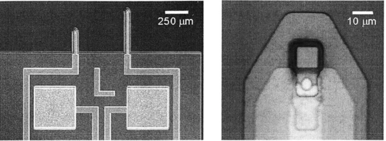
Examples of the previous lot of devices used for these experiments are shown in Fig-ure 3.2 [19]. The junction between the silicon sensor area and the aluminum trace is clearly shown. The metal trace extends down the length of the cantilever. After aluminum deposition, the device can undergo no more high temperature process-ing. The melting temperature of aluminum, 660 C, limits the operating temperature of subsequent processing steps. Ideally, it would be desirable to passivate the de-vices with a high-quality, defect-free dielectric. Thermal diffusion of silicon dioxide is materially incompatible with the metalization and requires high temperature. Low-pressure, chemical vapor deposition (LPCVD) nitride also requires high-temperature deposition.
Due to processing temperature constraints, the devices were passivated with low-temperature oxide (LTO) and plasma enhanced chemical vapor depostion (PECVD) nitride. While LTO can be deposited with nearly arbitrary stress with regard to the substrate, it lacks the density of thermally diffused oxide. Although there have been reports of low-defect, robust PECVD nitride layers, deposition can be highly variable and difficult to reproduce. Deposition depends on factors difficult to control in a multi-user university research facility.
3.2
New Design
3.2.1
Passivation
Cleaning the previous lot of SPP devices with piranha has not been successful, most likely due to failure of the passivation layer. For this reason, metal has been
elimi-Figure 3-2: Optical Micrograph of Original SPP devices. Active area is square region on tip at right. Metalization junction is circular overlap of silicon and aluminum (brighter).
nated from the cantilever structure in the devices fabricated and demonstrated here. Instead, highly-doped silicon is used as a the electrical trace. This doped-silicon elec-trical trace is then passivated with thermal oxidation. Aluminum is deposited on the electrode contacts on the die later in the processing. These contacts are used to wire-bond the devices to ceramic test chips. The wire bonds and contacts on the bulk of the device are then coated with RTV (silicon, dow corning), which is inert to our cleaning procedures.
3.2.2
SiO2-Si3N4 interface
Previous devices have featured an active sensor area composed of nitride with a thin adhesion layer of oxide. Nitride was chosen for its nearly linear relationship between surface potential and pH over a broad pH range. The oxide-nitride interface contains many charge traps that are difficult to anneal because forming gas has difficulty permeating the nitride layer. Charge trapped at the silicon-oxide interface can migrate to the oxide nitride interface at moderate bias voltages, causing irrevocable shifts of electrical properties in the device. This effect was first investigated by Chu, et. al.
[11], and has subsequently been investigated as a type of non-volatile memory [1, 10].
Further, cleaning devices with oxygen plasma can also implant charge at the oxide-nitride interface.
The nitride layer has been eliminated from the fabrication process, in favor of a silicon dioxide sensor surface. Surface states present after the oxide diffusion can be repaired with a forming gas anneal performed at 400 C for 30 minutes in a 95:5 mixture of nitrogen and hydrogen respectively.
3.2.3
Stress Balancing in SiO2 layers and Dopant Diffusion
The processing of the SPPs begins with double side polished silicon-on-insulator (SoI) substrates. The buried oxide layer eventually serves as the backside passivation for the cantilevers. The silicon device layer forms the sensitive region and electrical trace for the SPP. The previous devices used nitride as the backside passivation layer and low-temperature oxide as the frontside passivation layer along the trace on the cantilever. These films allowed the cantilevers to be relatively low-stress structures.
The interface between silicon and thermally grown silicon dioxide, however, has 0.2 - 0.3 gPa compressive stress, which can cause significant beam deflection. In order
to minimize out of plane deflection of the cantilever, it is necessary to match induced stress at the inteface between buried oxide layer and the silicon device, and that at the interface between the silicon device and the diffused oxide layer on the top. This can be accomplished by matching the thickness and diffusion conditions.
The redesign of the SPP relies on a region of highly-doped silicon acting as a metal trace connecting the sensitive region at the tip of the device to a metal electrode on the bulk of the device. We desire this trace to have a low-resistivity, and for the doping profile to be fairly uniform over the cross-section of the device. The dopant concentration profile in the device is defined by by a long diffusion step that both diffuses the dopant and grows the top thermal oxidation layer.
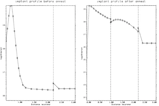
In order to determine the ion implant dose and energy, and diffusion conditions to ensure low-resistivity of the trace and matched interfacial stresses, these steps were simulated using TSUPREM4. Source code for these models are given in Appendix
A. The simulated dopant drive-in, shown in profile in Figure 3.3, results in a fairly
uniform concentration profile of about 1018cm-3. Lateral diffusion is moderate, about
1 micron, and should not completely close off even the smallest active areas of 5
microns on a side.
The expected sheet resistance of the highly doped silicon trace can also be ex-tracted from this model and is simulated to be 319 ,1 square. For the dimensions of the device, the total resistance of the trace would be 44 kQ. The chosen ion implant dose
was somewhat conservative as the solid solubility of boron is on the order of 102 1cm
-3, much higher than the achieved concentrations. The resistance of the electrical trace could theoretically be reduced to hundreds of Ohms.
3.2.4
Wafer through-etch Release
Releasing fragile surface-micromachined structures, such as the cantilevers in this process, is a difficult challenge in any micromachining project. For through-wafer etch, either bulk wet-etch chemistries or Deep Reactive Ion Etch (DRIE) techniques can be considered.
pyrochate-chol) and alkali hydroxide etchants such as KOH (potassium hydroxide) and TMAH (tetramethyl ammonium hydroxide). Masking layers for these chemistries typically include silicon dioxide or silicon nitride. For our process, we would need to confor-mally coat the front side to protect it from etching. Neither oxide nor nitride can be used for this, because we would have to rely on a timed etch to remove the masking layer and leave the device layers of these materials. Other polymers and waxes can be used for frontside protection, but are not as robust and are also difficult to remove.
implant profile before anneal
1.00 1.0 2.00
Distance (m~icr-ons)
implant profile after anneal
19 18s 17-it 15 14 12 2.50 3.06 0.00 0.50 1.00 1.50 2.00 Distance (miicrons)
Figure 3-3: TSUPREM4 simulation of dopant diffusion and oxidation. The left figure shows implant profile before dopant diffusion. The line at 2.2 pm marks the lower boundary of the silicon, where it contacts the buried oxide layer of SOI. The right figure shows the implant profile after the diffusion step where the dopant is driven into the surface, and the passivation oxide is grown. The passivation oxide extends from 0-1 ym, the silicon from 1 to 2.2 pm, and the buried oxide is beyond 2.2 gm into the device.
DRIE allows the use photoresist and a carrier wafer for frontside etch protection. The directionality of the plasma etch is great advantage for this process, considering the difficulties associated with frontside protection for wet processes. Extremely high aspect ratio structures have been defined with this method [2] and the etch rate is comparable to that of wet-etch techniques, about 1 micron per minute. This is acheived by cycles between isotropic etching with SF6 and a sidewall passivation with a fluoropolymer.
After the surface micromachining of these devices was completed, the devices were
19
-
18-
17-is
mounted face down on a carrier wafer coated with 10 pm of thick resist. The carrier wafer serves two main functions. First, the plasma etch can load the wafer, such that the wafer cleaves along "streets" of photolithographic patterns aligned along the natural cleaving planes of the wafer. The carrier wafer provides structural support for this scenario. The second effect to consider involves the cooling mechanism of DRIE etch. The wafer is cooled by being held against a chamber of cooled helium. Without the carrier wafer, helium can leak into the chamber when the through-etch is complete. The helium damages the chamber and adversely effects subsequent etching. If the frontside were only protected with a thick layer of photoresist, when the silicon has been cleared out, leaks can easily form in the photoresist.
A schematic of the mask set used is shown in Figure 3.4. Devices were fabricated
with square active areas 5, 10, 20, 50, and 100 ,um on a side. The process flow of the design presented here is shown in Figure 3.5. For complete processing details, please see Appendix C.
MASK 1 Ion inplant nask
of active area
MASK 4 Ccntact Cuts
MASK 2
Silicm tram defi
MASK 5 btal direct etdi
MASK 3
Open. up aperture far active arsa
MASK 6 Backside mask
fcr release
Figure 3-4: Mask Schematic, not to scale. Cut lines show where cross-sections in process flow are taken.
Figure 3-5: Revised Process Flow
Siliccn diaxice
LI
Lightly dped SiliconHighly doped Silicon Aluminum
1) Starting Material:
SOI wafers, single-side polished
Device: 2.2 um, p-type and n-type, 4-6 ohm/cm
Handle: 525 um, p-type and n-type, 5 ohm/cm
Oxide: 1.1 um
Send out to have backside polished to facilitate
backside alignment.
2) Pre-metal clean: Double piranha, HF dip
3) RCA clean
F7777
77+ 4) Diffuse oxide for doping mask -1.4 gm thick, leaving 1.5 um Si5)Pattern doping mask (MASK 1)
6) Plasma etch oxide -1.4 tm 7) Ash photoresist
8) Send out for heavy phosphorus doping: 9) Pre-metal clean
10) Pattern Si to define device (MASK 2)
11)Plasma etch Si (approx. thickness now 1.5 gm) 12)Strip Photoresist
13) Etch masking oxide: BOE -14 minutes
15) Grow thick oxide to match buried oxide -1.1 gm thermal oxide
16) Pattern aperture for active area (MASK 3)
17) Plasma etch oxide in aperture
18) Strip photoresist piranha
19) RCA clean
20) deposit active area: just oxide 900 A
21) Pattern contact cuts and device definition
(MASK 4)
22) Etch through oxide (900 A)
23) Strip PR in piranha, HF dip
for metalization descum 24) Aluminum deposition 5000 A
25) Contact patterning(MASK 5)
26) Direct etch aluminum (PAN etch)
27) Ash photoresist
29) Spin-on thick resist for frontside protection
30)Plasma etch backside oxide (900 A)
31) Pattern thick photoresist for backside
etch mask (MASK 6)
32)Frontside protection, cleaving protection: apply thick photoresist to carrier wafer device wafer face down on carrier wafer
33) DRIE etch handle to release structures
34) Strip PR in acetone to release carrier wafer, Rinse in methanol, 2-propanol
35) break out devices, ball bond.
3.3
Fabrication Results
The most challenging aspect of this process was the release of the cantilevers and the dismount from the carrier wafer. An ideally released device is shown in Figure
3.6. However, the DRIE showed about a 60 pm etch variation across the wafer, such
that the first devices cleared out about and hour before the final devices cleared out. This had two main implications. First, the first devices to release were exposed to about 1 extra hour of etching. This overetch caused footing [3], or undercutting of the cantilever structures. Although the masks were designed to tolerate some undercutting as well as back-to-front alignment error, the undercut devices were left dangling by a thin wire of highly doped silicon and a shelf of oxide. Examples of over-etch and under-etch are show in Figures 3.7 and 3.8.
The second main effect is that the buried oxide layer became significantly etched on the devices which cleared out first. The silicon:oxide etch ratio is about 100:1, so over half a micron of the 1.1 ym of buried oxide was etched. In spite of this, even the devices that were substantially over-etched do not bend out of plane significantly. SPP tips were typically deflected about 25 pim out of plane.
Etched wafers were dismounted from carrier wafers by either soaking in acetone, or in Microstrip at 80 C. The cantilevers were extremely sensitive to any frictional forces caused by partially dissolved photoresist and were therefore extremely sensitive
to handling. This problem was exacerbated by hard-baking of photoresist during the long etch. Indeed, most of the cantilever breakage occurred from sliding across the carrier wafer surface while partially dissolved photoresist remained. A typical example of is shown in Figure 3.9. Figure 3.10 shows a close-up of damage.
Figure 3-6: Optical micrograph of an ideally released pair of probes. devices is 15 pm on a side.
The active area on these
It
Figure 3-7: Optical micrograph of underetched structure.
Figure 3-9: Optical micrograph showing details of typical breakage scenario. Devices were weak-ened by over etch. Frictional forces due to gummy, partially dissolved photoresist caused breakage.
Chapter 4
Experimental
4.1
Experimental Setup
After fabrication, the electrical properties of the devices were characterized by mea-suring the response of photocurrent vs. voltage.
Devices were mounted with five-minute epoxy on ceramic test chips and then gold ball bonded to gold pads on the chips. The wire bonds were coated with silicone (RTV) primarily for mechanical protection. The RTV is also inert in common buffer solutions and resistant to the piranha used for cleaning.
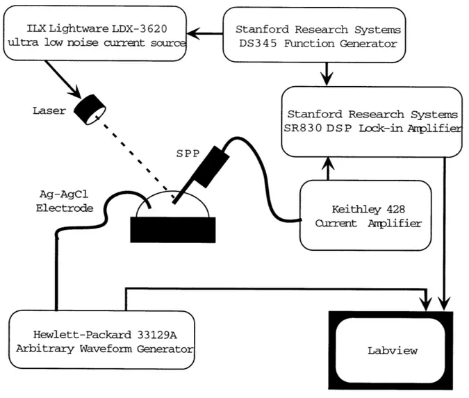
A schematic of the amplification and readout circuitry is shown in Figure 4.1. All
I-V characteristics were taken in pH 7.4, 0.1 M PBS buffer. A droplet of PBS buffer was formed on a fluid cell and a silver-silver-chloride electrode was used to contact the solution. A 635 nm-wavelength laser is focused to a 10-pm diameter spot on the active area of the device and amplitude modulated with a 2 or 3 kHz square wave at
1 mW. The photocurrent signal is amplified with an Keithley current pre-amp set at
107 V. The RMS amplitude of the photocurrent signal is extracted with an SRS
Lock-in amplifier synchronized with the TTL signal of the function generator drivLock-ing the laser. The voltage bias applied to the fluid electrode is generated by an HP waveform generator. For the I-V curves, a triangle wave of +2 volts at 20 mHz is used. Data is acquired and processed using National Instruments LABVIEW software.
4.2
Photocurrent Response
Detection of the sensor surface potential is based on making a capacitive measurement of the depletion region width. The method of detection used here to characterize the device is based on optical generation of electron-hole pairs. The excess carriers are
ILX Lightware LDX-3 620
ultra low noise current source
Laser
Ag-Elec
Stanford Research Systems
DS3 4 5 Function Generator
Sta SR8
nford Research Systems
3 0 D S P Lock-in Arplifier Keithley 428 Current Anpliflier SPP AgCl trode
I
4
Hewlett-Packard 33129AArbitrary Waveform Generator
[
LabviewFigure 4-1: Experimental Setup
separated by the electric field in the depletion region. A transient photocurrent is observed as the carriers reach a new equilibrium state, with minority carriers drifting to the top surface and majority carriers drifting pushed into the bulk of the device. The photocurrent response of the device is shown in Figure 4.2 for a device biased in inversion. The corresponding binary laser signal is inset.
When the structure is biased at its flat-band voltage or in accumulation, we expect there to be no photocurrent since there is no electric field at the top surface. The maximal photocurrent response is expected when the device is biased in inversion, such that any extra minority carrier accumulate in a plane at the top surface.
100 04 0 0 50 0 -50 -100 -150 0 500 1000 1500 2000 Time (microseconds)
Figure 4-2: Photocurrent vs. Time
4.3
Current vs. Voltage Response before and after
H
20 2+ H
2SO
4cleaning
Figure 4.3 shows the photocurrent vs. voltage response of a device with a 10x1O square prm area. A full cycle of change in bias voltage is shown in order to charac-terize hysteresis. Figure 4.3a) shows the I-V characteristic of a device that has not been dipped in piranha. Several aspects of this plot are worth noting. First, the pho-tocurrent is very nearly 0 for voltages below a bias of about -1.5 V. This is indicative of a successful anneal of surface sites at the Si-Si02 interface. Previous devices have shown less-ideal current response in the accumulation region, with the photocurrent amplitude increasing again after transitioning though a flatband voltage. Secondly, the most sensitive region of operation shows a nearly linear response of 240 ! and shows little hysteresis. Finally, at high applied positive bias, when the device is in in-version, the response is not ideal. In a bulk LAPS device, the photocurrent amplitude plateaus as the device becomes inverted[9, 8, 16]. Here, the photocurrent continues to increase, after a brief plateau and is hysteretic.
Laser: on ' ' ' I 'I ' I I I I I I I I I I I I ! ! . I . i i i I i
JL
rL
f L7
There are a few factors which may contribute to this non-ideal behavior. The first to consider is that the SPPs fabricated here differ from LAPS structures in that they are thin-film devices, fabricated on SOI. The final silicon layer is about 900 nm thick, and the maximum depletion region for the device is theoretically calculated to be 630 nm (see Appendix B for calculation). It is possible of that processing variations could produce a device whose silicon layer is about the same thickness as the depletion region and the device is becoming completely depleted. Another possibility is the onset of a second depletion region on the back surface of the device, which is passivated with a much thicker layer of oxide than the active area. Finally, charge traps in the oxide passivation layer or charged polymer residue may affect the response of the device.
Figure 4.3b) shows the characteristic for the same device after it has been cleaned
in piranha. The cleaning procedure is to dip the cantilevers in a 1:3 H20 2:H2SO4
(piranha) bath for 5 seconds, followed by a rinse in de-ionized water for 1 minute. The device shows less hysteresis in the inversion region. The fact that no direct current flows through the device indicates successful passivation and reliability after cleaning.
3 I I I I I I I I I I I I I I I I I I I I I I I I I I I I I I I I I I I i
a) before clean
2.5 2 1.5 1-0.5 0 -0.5 -2 -1.5 -1 -0.5 0 0.5 1 1.5 2 25-b) after clean
2 --1.5 1 0.5 0--0.5 -2 -1.5 -1 -0.5 0 0.5 1 1.5 2Voltage Applied to Electrolyte (volts)
Chapter 5
Conclusions and Directions of
Future Work
The design of the scanning probe potentiometer presented here was motivated by the need for sensors robust enough to withstand biological surface preparation tech-niques. The realization of this goal prompted the elimination of metalization from the cantilever structure. The highly-doped silicon trace, coupled with the high-quality thermal silicon dioxide passivation have demonstrated advantages over previously mi-cromachined devices. These include higher sensitivity, ideal (negligible) current when biased in accumulation, and, most importantly, compatibility with cleaning methods for biomolecular immobilization.
The detection method presented here, based on optical excitation of carriers, may not be the most ideal for experimentation. While this method is well suited to electri-cal characterization of the device, as experimentation progresses, it maybe advanta-geous to eliminate the laser from the detection scheme and instead use a capacitance method, such as described for scanning capacitance microscopy [27]. In this arrange-ment, the depletion width response to surface potential changes would act to modulate a resonant circuit. This type of detection may be more immune to disturbances in fluid flow, such as level changes of the fluid with respect to the cantilever.
The demonstration of this tool paves the way for experiments such as those out-lined in Chapter 2. As these experiments progress, insight into preferred sensor surface topology will develop. Previous devices were developed to have the charac-teristic pyramidal scanning probe tip. The device fabricated here was designed to have a planar sensor surface, recessed from the electrical passivation. This decision was motivated by the desire to focus on experiments where the sensor surface is acti-vated, as opposed to having an arbitrary active area which is then scanned. Further, we were interested in demonstrating the functionality of the device with a simplified
topological structure. The development of a potentiometric scanning probe for charge imaging of arbitrary charged surfaces remains a goal, however, and this will probably require redesign of the sensor surface.
The release step and subsequent carrier wafer dismount remain the primary yield-limiting factors. These are subject to ongoing research in order to improve yield. Optimizations in doping, diffusion, and annealing steps can also improve device per-formance.
Appendix A
TSUPREM4 Simulation Code
$SPP dopant diffusion and oxidation simulation $this only does one half of the mirror image
LINE X LOC=O SPAC=.2 tag=left
LINE X LOC=6 SPAC=.2 tag=right
LINE Y LOC=O SPAC=.2 tag=topsi
LINE Y LOC=2.2 SPAC=.2 tag=topox LINE Y LOC=3.0 SPAC=.2 tag=backox
$SOI
region oxide ylo=topox yhi=backox xlo=left xhi=right initialize <100> boron=2e16
diffusion time=160 temp=1100 weto2 etch oxide left pl.x=3
$plot oxidation and etch
option device=ps file.sav=thl.ps
select z=1 title="Masking Oxide: Initial Structure" plot.2d axes scale boundary grid
color oxide color=1 color silicon color=2 $do dopant implant method compress
implant dose=1e15 energy=50 boron
etch oxide isotropi thickness=1.4
$plot structure
option device=ps file.sav=th2.ps
select z=loglO(boron) title="after implant: contours"
plot.2d clear
foreach x(15 16 17 18 19 20 21)
contour val=x color=2 end
option device=ps file.sav=th3.ps
select z=loglO(boron) title="implant profile before anneal"
plot.1d x.v=1 symb=1 boundary axes
save out.file=sppthesis.str
initialize infile=sppthesis.str
$dopant diffusion and passivation oxidation
diffusion time=145 temp=1100 weto2
$plot structure
option device=ps file.sav=th4.ps plot.2d axes scale boundary grid color oxide color=1
color silicon color=2
$plot dopant contours
option device=ps file.sav=th5.ps
select z=loglO(boron) title="after implant contours"
plot.2d clear
foreach x(15 16 17 18 19 20 21) contour val=x color=2
end
$plot profile
option device=ps file.sav=th6.ps
select z=loglO(boron) title="implant profile after anneal" plot.1d x.v=1 symb=1 boundary axes
initialize infile=sppthesis2.str
$extract electrical characteristics
ELECTRIC X=1.0
save outfile=sppthesis3.str
$$result of running this program:
********************** STRUCTURE INFORMATION ***********************
LAYER MATERIAL THICKNESS REGION DIFTYP THICKNESS TOP BOTTOM
3 oxide 2 silicon 1 oxide Bias step 1.0649 1.2312 0.8000 1 1.0649 p 1.2312 0.8000 1: 0.00 (Volts)
Material Thickness Type Junction Depth Sheet Resistance
oxide 1.06 um silicon 1.23 um P 1.23 um 319 ohm/sq oxide 8000 A -0.0961 0.9688 2.2000 0.9688 2.2000 3.0000
Appendix B
Theoretical Derivation of
Depletion region width
The initial p-type silicon device substrate is doped to a resistivity of 5Q -cm. First, we need to find the dopant concentration, NA. Resistivity, p, is defined as
1
w-where the conductivity, a, is defined as
a = q(noue + Poph),
and po and no are carrier concentrations. For p-type silicon,
Po = NA + ~ NA, NA n? NA ' or-=q(NAI-e + *i Ph), NA q = 1.6 * 10-19C,
electron and hole mobilities are CM 2 ple= 1500
v
Cm 2 A6= 600V
ni = 1.08 * 10'0cm~3, yields NA = 2.08 * 10 1 5cm-3.The maximum depletion width in a bulk silicon device occurs when the surface potential reaches twice the work function of the silicon and is:
Xd 2ES (2<bP) qNA where 2kT NA q ni For T = 300K, Esi = 11.7 * 6O, C2 60 = 8.85 * 10-~ 2 NC22 Nm2 k = 1.38 * 10-23J K' xd = .626 pm.
Appendix
C
Fabrication Details
For this research, p-type devices were fabricated by a six-mask process. The start-ing wafers were sstart-ingle-side polished Silicon-On-Insulator (SOI) donated by Analog Devices. The key physical and electrical properties of these wafers are:
The wafers were backside polished out of house before processing in the MIT Microsystems Technologies Laboratories was begun. The backside polish of the wafers facilitated backside alignment of the final mask for the cantilever release. Devices with two type of active areas were fabricated: a 900 A oxide active area, and an 900 A oxide adhesion layer with a 450 A nitride active area.
All fabrication, except as noted, was carried out in the MTL facilities.
Fabri-cation was done in the Integrated Circuits Laboratory (ICL), a class 10 cleanroom facility and Technology Research Lab (TRL), a class 100 cleanroom facility, as desig-nated. Common steps are described in detail at their first occurrence and abbreviated thereafter.
Layer Thickness (pum) Resistivity (Qcm)
Handle Silicon 525 5
Buried Oxide 1.1
Step Description
Pre-metal clean (ICL)
10-minute Piranha (1:3 H202 : H2S0 4), rinse, repeat
30 s HF dip, rinse
spin dry
2 RCA clean (ICL)
10 minute organic clean (5:1:1 H20
rinse
15 s HF dip
rinse
15 minute inorganic clean(6:1:1 H20
rinse spin dry
3 Diffuse thermal oxide (ICL)
Recipe: 224
H202 : NH 40H)
H202 : HCl)
Temp (C) ITime (min) Gas
800 10 02 1100 30 02 1100 20 02 1100 10 HCl 1100 10 HCl 1100 150 N20 1100 20 HCl 1100 20 02 4 Pattern doping HMDS mask (MASK 1) (TRL)
Spin on standard OGC825 resist to 1 pm Prebake 30 minutes, 90 C
Expose 45 s, 320 nm, 6w; Develop in OGC 934 1:1 Postbake 30 minutes, 120 C
5 Oxide etch (ICL) AME5000
Time (s) Gas Rate (sccm) Servo (W) Pressure (mT) Magnetic Field (Gauss) 25 02 20 0 200 50 20 02 20 100 200 50 25 CF4 15 0 200 50 25 CHF3 10 0 200 50 550 CHF3 10 0 350 50
6 Ash photoresist (ICL)
7 Send out for heavy boron doping
dose: lel5 energy: 50 keV
8 Pre-metal clean (ICL)
9 Pattern silicon to define device (MASK 2) (TRL) HMDS
Spin coat 6 pm thick resist AZ 4620
Prebake 60 minutes 90 C 460 s exposure, 320 nm, 6 '
Develop in AZ 440
Postbake 30 minutes 120 C
10 Plasma etch silicon
Due to lengthy disrepair of ICL silicon etcher, this step was done at Stanford's CIS facilitiy on the Drytek2 by Steve Minne. The main etch step used SF6 at 150 sccm, 100 mTorr of pressure
500 W power, and 11-12 minutes etch time until clear.
11 Pre-metal clean to strip photoresist, no HF dip (ICL) 12 Etch masking oxide (ICL)
20 minutes to de-wet in Buffered Oxide Etch (BOE)
13 RCA clean
14 Diffuse thick oxide passivation (ICL)
Recipe 224 listed above, 135 minutes on variable time N20 step
UV1280 measurement shows 10600 A
15 Pattern aperture for active area (Mask 3)
HMDS, spin 2.5 pm OGC 825 resist, prebake on coater track (ICL)
Expose 15 s, 365 nm, 9 w (TRL)
Develop in OGC 934 1:1 (TRL)
16 Plasma etch oxide over active area (ICL) AME5000, Isabel LTO, listed above
520 s, including overetch
17 Pre-metal clean to strip photoresist, no HF dip (ICL) 19 RCA clean (ICL)
20 Dry thermal oxidation of recipe 121:
active areas (ICL)
Temp (C)
J
Time (min) Gas800 10 H2 1000 20 02 1000 20 02 1000 205 HCI 800 20 02 800 25 02
22 UV1280 measurements (ICL) oxide devices: 970 A oxide
23 Pattern contact cuts and deice definition (MASK 4) (TRL) HMDS, 8 prm thick resist, prebake
expose 20 s 365 nm at 9 ' develop, postbake
24 Etch contact cuts (ICL)
AME5000, oxide etch on all wafers 25 Pre-metal clean (ICL)
26 Sputtered deposition of 5000 A Aluminum (ICL) AMAT Endura
27 Pattern metalization for direct etch (TRL) HMDS, spin-coat 7 prm thick resist, 1 hour pre-bake
Expose 400 s 320 nm, at 6 2
28 PAN (wet) etch of aluminum (ICL) until clear 29 Solvent (Microstrip) photoresist strip (TRL) 30 Coat frontside for handling protection
HMDS
Spin coat 10 pm thick resist Bake 30 minutes at 90 C
31 Pattern backside to open up oxide for release (TRL)
spin coat 1 ptm OGC 825 prebake 30 minutes, 90 C develop KS2, 45 s
postebake 30 minutes, 120 C
32 Etch oxide (ICL) AME5000
Photoresist did not hold up in etch, had to repattern for release
33 Overnight soak in acteone to strip PR
with subsequent acetone soak in ultrasonic bath. rinse in methanol and 2-propanol
DI rinse
34 Frontside protection and backside repattern HMDS
Spin on 10 pm thick resist AZ 4620 on front side. Softbake 30 minutes at 90 C
Spin on 10 pm thick resist on back side Softbake 30 minutes at 90 C
Expose 25 s, 365 nm 9mw
Develop in AZ 440 until clear Postbake 30 minutes 120 C
35 Mount on carrier wafer
Spin on 10 pm thick resist AZ 4620 on carrier wafer in ring pattern Set device wafer front side down on carrier
36 DRIE etch to release cantilevers
MIT recipe 69A, 3-4 hours until clear everywhere
37 Dismount device from carrier
Soak in acetone overnight to dismount, accelerate with ultrasonic Rinse in methanol, 2-propanol, DI
or soak in Microstrip at 80 C
Bibliography
[1] H. Amjadi, Charge Storage in Double Layers of Silicon Dioxide and Silicon Nitride
8th International Symposium on Electrets (ISE 8), 1022 (1995).
[2] A.A. Ayon, R. Braff, C.C. Lin, H.H. Sawin, and M.A. Schmidt, Characterization of a time multiplexed inductively coupled plasma etcher, Journal of the
Electro-chemical Society, 146, 339 (1999).
[3] A.A. Ayon, K Ishihara, R.A. Braff, H.H. Sawin, and M.A. Schmidt,
Microfab-rication and testing of suspended structures compatible with silicon-on-insulator technology, Journal of Vacuum Science and Technology B, 17, 1589 (1999). [4] P. Bergveld, Development of an Ion-Sensitive Solid-State Device for
Neurophys-iological Measurements, IEEE Transactions on Biomedical Engineering, 19, 70
(1970).
[5] P. Bergveld, Development, Operation, and Application of the Ion-Sensitive
Field-Effect Transistor as a Tool for Electrophysiology, IEEE Transactions on
Biomed-ical Engineering, 19, 342 (1972).
[6] G. Binnig, C.F. Quate, and Ch. Gerber, Atomic Force Microscope, Physical
Re-view Letters, bf 56 930 (1986).
[7] L. Bousse, D. Hafeman, and N. Tran, Time-dependence of the Chemical Response
of Silicon Nitride Surfaces, Sensors and Actuators B 1, 361 (1990).
[8] L. Bousse, J.C. Owicki, and J.W. Parce, Biosensors with Microvolume Reaction
Chambers, in Chemical Sensor Technology, edited by S. Yamauchi (Kodansha, Tokyo and Elsevier, Amsterdam, 1992), Vol. 4, pp 145-166.
[9] L. Bousse, S. Mostarshed, D. Hafeman, M. Sartore, M. Adami, and C. Nicolini,
Investigation of carrier transport through silicon wafers by photocurrent measure-ments, Journal of Applied Physics 75, 4000 (1994).
[10] H.C. Card and M.I. Elmasry, Functional Modelling of Non-Volatile MOS Memory